SEI Industries BAMBI BUCKET SMALL Series User manual

BAMBI BUCKET
OPERATOR’S MANUAL
R

BAMBI BUCKET®
IssueDate:May2004
OPERATOR’S MANUAL
Please read before using Bambi Bucket
Manufactured under one or more of the
following patents:
U.S. Patents 4,576,237 and 4,474,245
Canada Patents 232,889 and 1,231,311
U.K. Patent 2,145,624B
SEI INDUSTRIES LTD.
7400 Wilson Avenue
Delta, BC, CANADA V4G 1E5
Tel: (604) 946-3131
Fax: (604) 940-9566
E-Mail: [email protected]
Web Site: www.sei-ind.com
US & International Inquiries:
SEI INTERNATIONAL SALES INC.
Suite #3, Beaumont House, Hastings,
Christ Church, BARBADOS
Tel: (246) 228-4908
Fax: (246) 228-3326
E-mail: [email protected]
Web Site: www.sei-ind.com
COPYRIGHT@ 2002 SEI INDUSTRIES LTD. ALL RIGHTS RESERVED
PRINTED IN CANADA

1. INTRODUCTIONTOTHE BAMBI BUCKET ......... 1
2. PREFLIGHT SAFETY CHECK ............................. 2
3. DEPLOYINGTHE BAMBI BUCKET ..................... 3
3.1 Attaching to Cargo Hook
3.2 Connecting Power
3.3 Checking Suspension Cable Length
3.4 Shortening Suspension Cables
3.5 Instant Deployment System (IDS)TM
4. FLYING THE BAMBI BUCKET ............................. 7
5. FILLINGTHE BUCKET ......................................... 8
5.1 Variable Fill Capability
5.2 Frusto-Conical Arrest SystemTM
(Cinch Strap)
5.3 Adjusting the IDS Adjustment Chain
5.4 Shallow Fill Capability
5.5 Filling from the Fireflex TankTM
6. USING FOAM ...................................................... 10
6.1 Bambi "Sacksafoam" Foam
Injection System
7. DUMPINGTHE BUCKET .................................... 11
7.1 Dump Pattern
7.2 Dump Speed
7.3 Reducing Mouth Opening of the
Dump Valve
8. LANDING ............................................................ 12
9. PACKING THE BAMBI BUCKET ........................ 13
10. STORINGTHE BAMBI BUCKET ........................ 14
11. ADJUSTMENTS .................................................. 15
11.1 Adjusting the Dump Valve "Udder"
11.2 FCAS and Valve Sealing
11.3 Adjusting "Udder" via Trip Line
11.4 Adjusting "Udder" Following Shortening of ...
Suspension Cables
11.5 Adjusting Purse Lines in Dump Valve
11.6 Checking Purse Line Adjustment
12. GENERALTROUBLE SHOOTING ..................... 18
12.1 Valve Troubleshooting
12.2 Control Head Troubleshooting
13. CONTROL HEAD MAINTENANCE .................... 21
13.1 Trip Line Replacement
13.2 Spring Power Reel Replacement
13.3 Catch Replacement
14. BUCKET MAINTENANCE .................................. 27
14.1 Purse Line Replacement
14.2 Suspension Line Replacement
14.3 M-strap Replacement
14.4 Dump Valve Replacement
14.5 Bottom Loop Repairs
14.6 Bucket Patching
14.7 Bucket Patching with a Hot Air Gun
14.8 Bucket Patching with Repair Clamps
14.9 IDS Hub/Spokes Replacement
15. WARRANTY ........................................................ 33
16. SPECIFICATIONS ............................................... 34
16.1 Capacity and Weight Specifications
16.2 Suggested Buckets for Different Helicopters
17. WIRING DIAGRAM ............................................. 36
18. CONTROL HEAD PARTS, .................................. 37
MODELS 6072-4453
18.1 Parts Diagram
18.2 Parts List
19. CONTROL HEAD PARTS, .................................. 39
MODELS 5566-HL5000 & HL7600-HL9800
19.1 Parts Diagram (5566-HL5000)
19.2 Parts List
19.3 Parts Diagram (HL7600-HL9800)
19.4 Parts List
20. SHELL ANDVALVE MODELS 6072-1821.......... 43
20.1 Parts Diagram
20.2 Parts List
21. SHELL ANDVALVE, ........................................... 45
MODELS 2024-HL9800
21.1 Parts Diagram
21.2 Parts List
22. RIGGING MODELS 6072-1821.............................47
22.1 Parts Diagram
22.2 Parts List
23. RIGGING, MODELS 2024-HL9800 ..................... 49
23.1 Parts Diagram
23.2 Parts List
24. IDS SYSTEM, MODELS 6072-1821.................... 51
24.1 Parts Diagram
24.2 Parts List
25. IDS SYSTEMS, MODELS 2024-HL9800 ............ 53
25.1 Parts Diagram
25.2 Parts List
26. PACKAGING........................................................ 55
26.1 Parts Diagram
26.2 Parts List
TABLE OF CONTENTS

BAMBI BUCKET SMALL SERIES 6072-4453

BAMBI BUCKET HEAVY LIFT SERIES 5566-HL9800

1
1. INTRODUCTION TO THE BAMBI BUCKET
This manual provides helicopter operators with information on the operation and maintenance of the Bambi Bucket.
Since its introduction in 1983, the Bambi Bucket has become the preferred means of helicopter fire fighting by over
600 companies and agencies worldwide. This acceptance by the industry is a result of the Bambi’s effectiveness,
reliability, simplicity and ease of use.
The operation of the Bambi Bucket can be quickly mastered by operators with no prior experience. The bucket
requires no pre-assembly. Once airborne, the operator quickly becomes familiar with the flight characteristics of the
bucket. Several fills will provide familiarity with the variable fill capability of the bucket.
Please read this manual prior to flying the bucket, particularly the sections on deploying, filling and dumping. If
problems are experienced, please refer to the manual. Section 11 on “Adjustments” and Section 12 on “Troubleshooting”
may be especially helpful.
For your own protection and for longer bucket life, always heed the instructions and warnings. Ignoring them could
result in bucket or aircraft damage or personal injury. The warning notices are divided by the severity of the outcome
into WARNING and CAUTION.
WARNING: Hazards or unsafe practices which could result in personal injury or death.
CAUTION: Hazards or unsafe practices which could result in minor personal injury or property damage.
SEI offers complete parts supply and repair facilities for the Bambi Bucket. For maintenance and repair purposes,
parts diagrams and descriptions are provided in Sections 18 to 26. When ordering parts, please provide the Model
and Serial number of your Bambi Bucket.
Additional copies of this manual are available from SEI Industries Ltd.

2
2. PREFLIGHT SAFETY CHECK
Just as the pilot preflights his aircraft, he should also
preflight his Bambi Bucket each day. Start at the bottom
of the bucket and work up:
1) Check the bottom chain and look for any tears
in the fabric straps; check the lockwire or tie wraps on
the shackles.
2) Check for loose bolts around the bucket shell: IDS
brackets at the top, FCAS (Cinch strap) brackets at the
midpoint, wear strips at the bottom.
3) Check the diagonal “M-straps” that connect the
suspension cables to the top of the bucket and examine
for any wear.
4) Check the purse lines on the dump valve. Frayed
lines should be replaced. Do not wait for a line to break
before replacing it.
5) Check the internal or external Frusto-Conical Arrest
SystemTM (FCAS or cinch strap).
6) Check the suspension cables for frays, kinks or loose
swages.
7) Check that the ballast is securely attached.
Full ballast is essential for safe operation.
8) Check the control head for secure fittings. Never
operate the bucket with the control head cover removed.
9) Pull the trip line cable to full extension from the control
head and check for kinks, frays or loose swages.
10) Check solenoid operation.

3
3.1 Attaching to Cargo Hook
The Bambi Bucket is rigged for a lateral cargo hook.
Correct attachment is indicated when the name plate on
the control head faces forward in flight; this ensures that
the ballast on the Bambi will face forward in flight.
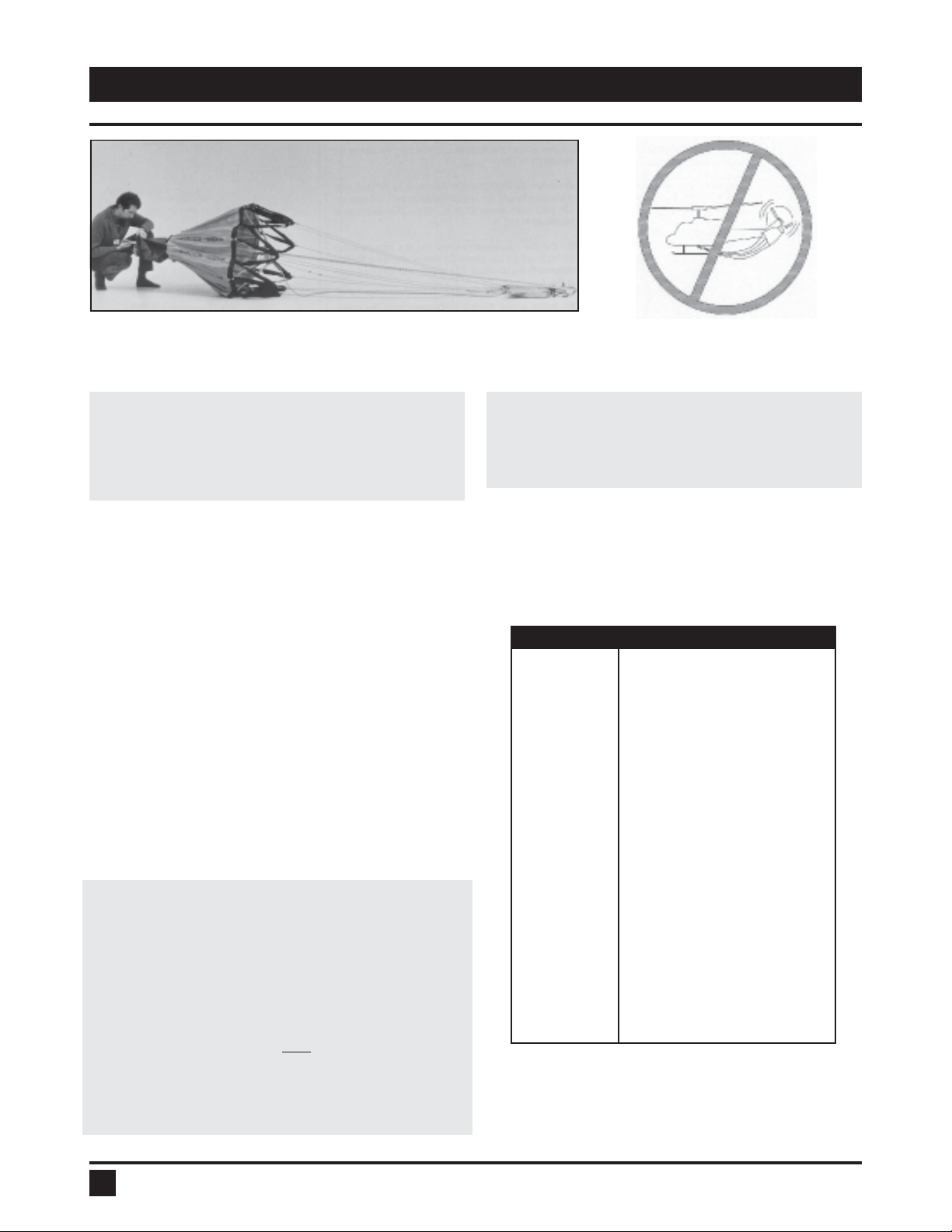
CAUTION: It is IMPORTANT that the ballast faces
forward In flight. This will avoid twisting of the
suspension lines and possible jamming of the
trip line.*
There are two different styles of control head used on the
Bambi Bucket. The head used on Models 6072-4453
has a moveable yoke which can be rotated by 90 degrees.
The yoke is machined to orient in either direction.
If your helicopter has a longitudinal hook, rotate the
shackle yoke unit at the top of the head by 90 degrees.
This will place the name plate on the control head forward
in flight.
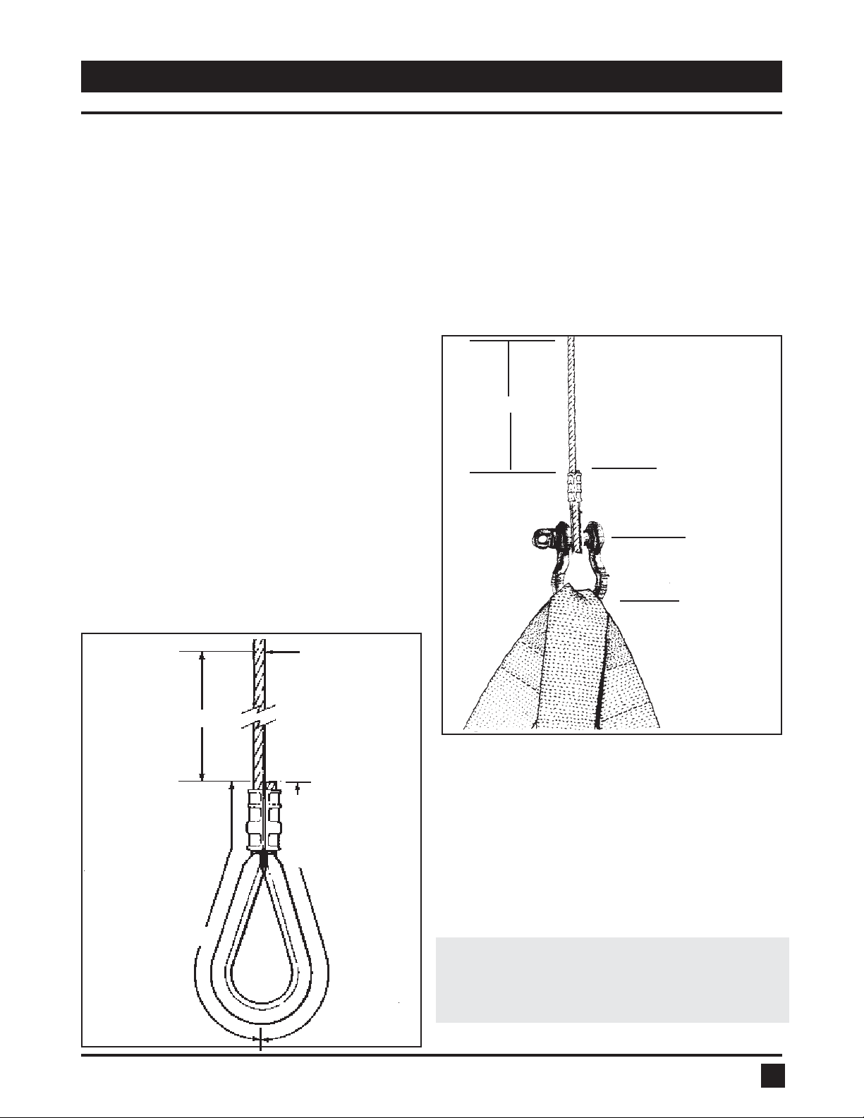
The head used on Models 5566-HL9800 is rigged for a
lateral cargo hook. It has a fixed top shackle. If your
helicopter has a longitudinal hook, use a second shackle
attached to the head shackle. This will effectively rotate
the attachment point by 90 degrees.
CAUTION: If using a second shackle on Models
HL5000-HL9800, it must have a load rating
equivalent to the top shackle supplied with the
head. Using a shackle with a lower load rating
could result in a shackle failure.
For either style of head, if using a swivel hook, operate in
the locked position to assure that the ballast is always
facing forward in flight.*
Caution: The Bambi Bucket may not be suitable
for a direct hook-up to the cargo hook. The
actual hook-up will be different for various
aircraft, and operators must comply to all
instructions and bulletins supplied by the
aircraft manufacturer. It is the operator's
responsibility to ensure that the Bambi Bucket
is correctly fitted to the helicopter.
3. DEPLOYING THE BAMBI BUCKET
3.2 Connecting Power
NOTE: To operate the solenoid and release the
water use a momentary contact switch rated only for
5.5 amps at 24 VDC. A suitable switch is available from
SEI. Alternatively, a lower rated switch may be used
with a relay--see suggested wiring diagram Section 17.
The solenoid has a 10% duty cycle. This means it is not
intended to be operated more than 10% of the time.
Operating the solenoid continuously will result in solenoid
failure.
The control head of the Bambi Bucket comes equipped
with a short length of two wire electrical cable. A popular
wiring hookup involves fitting a common household plug
to the end of the cable. To complete the wiring hookup:
1. Connect a 110 volt household plug to the wire
supplied on the control head.
2. Make a 12 AWG or heavier two wire interconnecting
electrical cable long enough to run from the bucket cable
to the accessory plug on the belly of the helicopter (leave
enough length for the control head to swing freely).
3. Attach the mating household plug to one end of the
interconnecting cable.
4. To check for continuity in the connections, push the
momentary contact switch. A clicking sound should be
heard from the control head.
5. With the engine running, test for a minimum of 24 VDC
at the breakaway plug (12 volts for 6072). If the voltage
is lower than 24 volts, use a heavier gauge wire for the
interconnecting cable. Re-test to confirm a minimum of
24 VDC at the breakaway plug.
The purpose of the household plugs is to offer a clean
“breakaway” if the Bambi Bucket has to be jettisoned
from the aircraft in an emergency. It is suggested that
the household plugs be lightly taped together with vinyl
tape while in use to ensure that wind action does not
separate the plugs. Current draw is only 5.5 amps. (24/
28 VDC)or 5.0 amps for 6072 (12-14 VDC).
*EXCEPTION: If you are using a swivel with an electri-
cal connection, then it is acceptable for the bucket to
be flown without the ballast facing forward. The Bambi
Bucket has been tested with the Canam Aerospace
swivel, and performs very well despite rotating in flight.
The swivel also prevents the suspension lines from
twisting up after dipping the bucket.

4
3.3. Checking Suspension Cable Length
WARNING: Using a Bambi Bucket with a greater
overall length than the distance from the cargo
hook to the front tip of the tail rotor on your
helicopter could result in a tail rotor strike and
possible loss of control of the helicopter.
Overall length of the Bambi with standard rigging is given
in Table 1. Before using your Bambi Bucket, check for
MAXIMUM TOTAL LENGTH. To determine MAXIMUM
TOTAL LENGTH, measure the distance from the cargo
hook to the front tip of the tail rotor on the helicopter you
will be using and subtract 6" (152 mm). To determine
overall bucket length:
1. Stretch out the Bambi on the ground; secure the control
head. See Fig. 2.
2. Pull out the dump valve fully; pull taut to ensure the
suspension cables are straight.
3. Measure the distance from the shackle on the control
head to the bottom of the dump valve. This measurement
should be less than the MAXIMUM TOTAL LENGTH
determined above.
3.4 Shortening Suspension Cables
If the overall length of the Bambi exceeds the distance
from the cargo hook to the front tip of tail rotor of the
helicopter, the suspension lines must be shortened.
3. DEPLOYING THE BAMBI BUCKET
Fig. 2: Measuring overall length of Bambi.
Model Overall Length
6072 12'11" 3.94 M
8096 14' 6" 4.42 M
8096 Short 12' 11" 3.94 M
9011 14'6" 4.42 M
1012 14'6" 4.42 M
1012 Short 12' 11" 3.98 M
1214 14' 10" 4.52 M
1214 Short 13'3" 4.04 M
1518 15'2" 4.62 M
1821 15'5" 4.70 M
2024 19'5" 5.92 M
2024 Short 16'4" 4.98 M
2732 23'0" 7.01 M
3542 23'5" 7.14 M
4453 23'8" 7.21 M
5566 24'7" 7.49 M
5566HD 24'7" 7.49 M
6578 25'1" 7.63 M
6578HD 25'1" 7.63 M
7590 30'6" 9.30 M
HL 5000 32'0" 9.75 M
HL 7600 33' 1" 10.08 M
HL 9800 34' 3" 10.44 M
Note: For Bambi Bucket Models 6578 sold prior to May 2001 the
overall length of the bucket is 31'2". Please specify model and
serial number when ordering parts.
Table 1: Overall lengths with standard rigging.
IMPORTANT:To avoid potential rotor strikes
when using the Bambi Bucket the operator must
measure the extended length of the Bambi
Bucket and the distance from the belly hook to
the closest possible point of the tail rotor.
A) Always measure the overall, extended length
of your Bambi Bucket.
And
B) Measure the distance from the belly hook to
the closest possible point on the tail rotor.
"B" must always exceed "A" by at least six (6)
inches.
Fig. 2A: Avoid Potential Rotor Strikes
IMPORTANT: It is recommended that operators
who choose to use the Bambi Bucket with a
longline, ensure the longline is at least 50' long.

5
3. DEPLOYING THE BAMBI BUCKET
Fig. 4: Cut 13' (330 mm) off the suspension cables.
trip line by the same amount as the suspension
cables.
8) Install a new thimble and sleeve and swage the
trip line securely.
9) Grasp the top shackle and extend the control head
to stretch out the suspension lines. Check for correct
cable sequence and/or twisted cables.
WARNING: For Models 6072 to 4453, do not
tighten control head suspension bolts over 5 ft-lbs.
(6.5 Nm) torque. Overtightening suspension bolts may
cause failure of control head casting.
passes around the thimble and into the new sleeve for
swaging.
Example: To shorten suspension cable by 19" (483 mm)
in effective length, cut original cable by 13" (330 mm) i.e.
19" (483 mm) minus 6" (152 mm). This example is
illustrated in Fig. 3.
3) Cut the suspension cables one at a time (to avoid
mixing them up) just above the swage where the thimble
attaches to the M-straps. Cut off 13" (330 mm) as shown
in Fig. 4.
Fig. 3: Shortening cable 19"(483 mm)
13" (330 mm)
BLACK M
STRAP
SHACKLE
COPPER SWAGE
BLOCK
CUT HERE
13" (330 mm)
SWAGING NEW
CABLE
ADDS
3" (76 mm)
3" (76 mm)
TOTAL CUT IS
13" (330 mm) +
3" (76 mm) +
EXTRA 3" (76 mm)
= 19" (483 mm)
4) lnstall a new thimble and sleeve onto the cable.
Swage the sleeve securely using the correct size swaging
tool.
5) Cut 13" (330 mm) off the IDS Deployment Cable as
shown in Fig. 5.
6) Install a new thimble and sleeve and swage the
IDS Deployment Cable securely.
7) Cut 32" (813 mm) off the trip line as shown in Fig. 6.
IMPORTANT: For Models 2024 - HL9800 shorten the
The following procedure reduces overall length by 19"
(483 mm). This 19" (483 mm) reduction in overall length
is standard when converting a bucket with regular length
suspension cables for operation with a McDonnell
Douglas, Hughes, or Schweizer helicopter.
1) The overall length reduced should be adjusted for your
specific overall length requirement.
IMPORTANT: Models 2024 - HL 9800 do not have a
pulley on the trip line. Shorten the trip line by the
same amount as the suspension cables.
2) In determining the new length, allow for the cable that

6
3. DEPLOYING THE BAMBI BUCKET
Fig. 5: Cut 13"(330 mm) off the IDS Deployment
Cable.
Fig. 6: Cut 32" (813 mm) off the trip line.
The Instant Deployment System uses a hub and spoke
mechanism to automatically expand the mouth of the
bucket as soon as the weight of the Bambi is taken by
the suspension cables.
When the bucket is full, the IDS Deployment Cable and
Hub Restrainer Cables should be slack; they should not
bear any load. Their function is to position the hub and
spoke mechanism to hold the bucket open.
The main parts of the IDS are illustrated in Fig. 7. To
deploy the IDS System on the ground, reach into the
bucket, grasp the hub of the IDS and pull outward fully
until the two cables from the hub to the lower bucket
shell are tight.
3.5 Instant Deployment System (IDS)TM
Fig. 7: Instant Deployment System, main parts.

7
4.1 Flying with the Bambi Bucket
The Bambi Bucket should be flown in accordance with
United States Forest Service recommendations limiting
all helicopters, OTHER THAN TANDEM ROTOR, to a
maximum 80 KIAS while conducting external cargo hook
operations.
We suggest building up speed slowly with the Bambi
Bucket on your helicopter, under the prevailing conditions,
to determine a safe maximum speed.
In order to reduce drag on the bucket when empty, it can
be flown in an open position by pressing the release
mechanism once while in forward flight.
4. FLYING THE BAMBI BUCKET
The dead weight of the load ensures different handling
characteristics than when flying empty. You will notice
that the Bambi Bucket does not ‘pulse’ or ‘throb’ under
load in flight.
Once the Bambi Bucket touches the water surface, it
immediately tips and sinks. This is a result of the ballast
on one side of the bucket which makes it unstable on the
water. You don’t have to tow the Bambi to make it sink.
IMPORTANT: When using the larger buckets, (Models
2024 and up) you may notice the dump valve does
not fully return after dumping. This is normal for the
larger model buckets. The valve will return as soon
as the bucket is immersed in water. To ensure the
valve is fully returned and locked, when filling, hit
the dump switch again when the suspension lines
are slack and before lifting out.
WARNING: When filling the Bambi, do not
execute an abrupt 90 degree pedal turn with
the helicopter close to the water while towing
the bucket. In this altitude, there is the danger
that the Bambi suspension lines (as with any
other external load) could get caught on a rear
skid resulting in a dynamic rollover on liftout.
This could cause personal injury and helicopter
damage. Check the load and suspension cables
with your mirrors before liftout.
5.1 Variable Fill Capability
The pilot can vary the bucket’s capacity by the speed at
which it is pulled from the water. As the submerged bucket
is lifted, water pressure bends the bucket shell and its
internal fiberglass battens outward, increasing the
bucket’s volume. The greater the pressure, the more
volume the bucket holds. That is:
A slow lift gives minimum fill.
A fast lift gives maximum fill.

8
5.2 Frusto-Conical Arrest SystemTM
(Cinch Strap)
The Frusto-Conical Arrest System (FCAS) allows the pilot
to reduce the volume of the bucket to a preset position.
The FCAS is composed of a cinch strap on the inside or
outside of the bucket. The cinch strap is marked with
one or more load levels. The illustration in Fig. 8 shows a
Bambi Bucket with volume reduced by cinching in the
bucket with the cinch strap. The cinch strap allows you
to reduce the volume of the bucket to lower levels than
can be done by straight fill speed alone.
When the cinch strap is tight, below 100% load
level, the trip line must be lengthened by
moving 3 or 4 links on the adjustment chain.
See Sections 11.1 and 11.3.
The bucket may not dump if the trip line is not properly
adjusted.
It is important to note that with the FCAS the top of the
bucket is always the spill line. The second that the bucket
breaks the surface of the water, it is ready to fly.
IMPORTANT: Varying the speed of the lift is often
the best way to adjust volume. This allows the pilot
to vary the load at each fill to best suit the fuel load
and prevailing lift conditions. Most pilots find it takes
a dozen or so fills to get the feel for the variable fill
action of the Bambi Bucket.
CAUTION: Do not tighten the cinch strap past
the smallest load marking. Overtightening can
damage the bucket shell.
5.3 ADJUSTING THE IDS ADJUSTMENT
CHAIN
An IDS adjustment chain is fitted to older models 2024 -
HL9800.This chain must be adjusted when using the cinch
strap to reduce bucket volume. The chain is lengthened
for lower fill settings (eg. 70%) to allow the IDS to rise
and thereby reduce IDS stresses.This will avoid possible
damage to the IDS.The chain is shortened for higher fill
settings (eg. 90%) to retain the maximum bucket mouth
diameter and hence allow maximum filling efficiency.The
recommended chain adjustments are summarized in Fig.
8.1.
5. FILLING THE BUCKET
Fig. 8: Bambi Bucket cinched in with the FCAS.
CAUTION: The lowest fill setting for all
models is 70%*. Overtightening the cinch strap
could damage the bucket.
*See Figure 5.5 for exceptions

9
5.4 Shallow Fill Capability
The flexible nature of the Bambi Bucket makes filling in
shallow ponds or streams easy.
The PowerFill II System has been designed to provide
the Bambi Bucket with shallow fill capability. The
PowerFill II is retrofitable to the Bambi Bucket and can
fill in 12 inches of water through an electric pump.
CAUTION: Snagging the Bambi on submerged
objects could result in bucket shell damage.
5.5 High Elevation Operations
Fire conditions in some areas require the reduction of
bucket loads to accommodate weight restrictions
caused by high elevation operations. For the short term
a 60% cinch strap may be used to increase the
cinching of the bucket to a 60% capacity. Extended
use of the 60% cinch may cause excessive stress
causing breakage of the battens.
For long term solutions - a smaller bucket, or the use
of a Bambi Bucket with a Torrentula Valve should be
considered.
5. FILLING THE BUCKET
Fig 8.1 Adjusting the IDS Adjustment Chain
Table 1: Standing height of empty buckets.
Bambi Bucket Empty Bucket Recommended FireflexTank
Model No. Height FireflexTank Full Height
(inch/M) Model No. (inch/M)
6072 28/0.71 FFTF-1518 48/1.22
8096 29/0.74 FFTF-1518 48/1.22
9011 29/0.74 FFTF-1518 48/1.22
1012 31/0.79 FFTF-1518 48/1.22
1214 33/0.84 FFTF-1518 48/1.22
1518 39/1.00 FFTF-3036 57/1.45
1821 41/1.04 FFTF-3036 57/1.45
2024 43/1.09 FFTF-4048 60/1.52
2732 48/1.22 FFTF-80100 79/2.00
3542 57/1.45 FFTF-80100 79/2.00
4453 57/1.45 FFTF-80100 79/2.00
5566 62/1.57 FFTF-80100 79/2.00
6578 67/1.70 FFTF-120144 93/2.36
7590 73/1.85 FFTF-120144 93/2.36
HL5000 80/2.03 FFTF-160190 100/2.54
HL7600 95/2.41 FFTF-176211 103/2.62
HL 9800 106/2.7 Contact SEI about the Heliwell Tank
5.6 Filling from the FireflexTankTM
The Fireflex Tank is a self-supported open top tank that
can be used as a dip tank for helicopters equipped with
the Bambi Bucket fire-fighting system. The following
table gives recommended tank sizes for different
models of the Bambi Bucket.
The HeliwellTM is a large capacity dip tank which can
hold up to 14,900 US Gallons. Due to its large size, the
Heliwell is an ideal transportable water source for large
Bambi Buckets as it is big enough to easily dip a 2,000
US Gallon Bambi Bucket.

10
The Bambi Bucket is designed to be effective with foam.
All materials used in the manufacture of the Bambi
Bucket are resistant the chemical action of foam.
CAUTION: After using foam or retardants,
cycle through several dumps with water only
or hose down with fresh water. This will
prolong the bucket life.
6.1 SACKSAFOAMTM Foam Injection System
TheSacksafoamTM isSEI Industries’stateoftheartfoam
dispensingsystem foruse with your Bambi Bucket. This
system, exclusive to the Bambi, allows foam to be
dispensedinto the bucketen route fromthefilling source
to the fire site.
Thereare fourmodels ofSacksafoamto fit thefull range
of Bambi Buckets. The operation of the Sacksafoam is
controlled by the pilot through a Control Unit, which is
mounted in the cockpit. This model of the Sacksafoam
contains the foam reservoir directly installed inside the
bucket.
Also available are the Sacksafoam II and III units, which
are self-contained units stowed onboard the helicopter.
The system is all housed in a foam-resistant case. With
the Sacksafoam II, the pilot still controls the foam
dispensing through the Control Unit. With the
Sacksafoam III, designed for medium and heavy lift
helicopters equipped with larger Bambi Buckets, the
operation of the system is performed by crew members
in the back. The Control Unit is mounted directly on the
caseof theSacksafoam III. SeeTable2 forSacksafoam
size requirements.
For further instructions on operating the Sacksafoam
units, please refer to the applicable Sacksafoam
Operator's Manual.
6. USING FOAM
Fig. 8.3 Sacksafoam Foam Injection System for the
Bambi Bucket
Model For Bambi Bucket Reservoir Capacity
USG Liters
Sacksafoam I
SFF01-8018 8096-1821 12 45
SFF01-2044 2024-4453 30 114
SFF01-5550 5566-HL5000 72 272
SFF01-7698 HL7600-HL9800 132 500
Sacksafoam II
SFF02-8044 6072-1821 10 38
SFF02-5598 1821-4453 25 94
SacksafoamIII
SFF03-6698 5566-HL9800 25 94
Sacksafoam Plus(foradditional foamstorageforSFII andSFIII)
SFF-PLUS 40 151
Table 2: Sacksafoam Models
Fig. 8.2 Sacksafoam III foam injection system for
medium and heavy-lift Bambi Buckets

11
To dump, simply hit the dump switch once and the rest
is automatic. The weight of the water inside the bucket
willcausethefabricdumpvalvetoturn inside-outthrough
the bottom of the bucket, thereby giving "obstruction-
free" passage to the escaping water and producing the
best possible dump pattern. You may wish to get in the
habit of hitting the switch a second time just before lift
out at filling to ensure that the release mechanism is in
the "locked" position.
IMPORTANT: When dumping the larger buckets,
(Models 2024 and up) you may notice the dump valve
does not fully return after dumping. This is normal
for the larger model buckets. The valve will return
as soon as the bucket is immersed in water. To en-
sure the valve is fully returned and locked, when
filing, hit the dump switch again when the suspen-
sion lines are slack, and before lifting out.
7.1 Dump Pattern
The dump pattern is affected by height and airspeed. It
is most concentrated at lower altitudes above ground
level (AGL) and at a hover. The pattern will “spread”
with height and speed. Most operators take advantage
of these characteristics to maximize their
assault on the fireline.
WARNING: Never dump onto ground
personnel as the water impact could result in
injury.
7.2 Dump Speed
Wesuggest that youget familiarwithflightcharacteristics
while dumping from your particular helicopter. Make
dumps at slower speeds before progressing to faster
dumps.
7.3 Reducing Mouth Opening ofThe Dump
Valve
The dump valve mouth can be reduced by bolting shut
some of the grommets in the dump valve itself, starting
with the outside edges of the valve and working in.
Always bolt in pairs, one grommet on one side of the
valve and its opposite on the other side.
Leave the purse lines in place when bolting to ensure
proper support for the valve.
You will find that if the valve is bolted down beyond a
certain point not alI the water will escape before the
spring power reel begins to pull the valve back in. This
necessitates the pilot hitting the dump switch a second
time to lock the release mechanism during the
next fill.
Experience has shown thatbolting the valvedownthree
grommets on each side reduces the water flow by 50%.
NOTE: It is uncommon for the valve to need to be
stopped down. Most operators regulate water
coverage with altitude and airspeed.
7. DUMPING THE BUCKET

12
Donotreleasethecontrolheadfromthecargo hook while
hovering. This could damage the control head. If the
control head must be released while hovering, have
ground personnel support the control head before
releasing.
CAUTION: If the control head has
experienced a severe impact, it is necessary
to visually examine the top stub of the control
head base casting to determine if it has been
bent or otherwise damaged. This examination
requires the unbolting and removal of the cast
yoke surrounding the stub.
If the stub is damaged, the control head base
casting requires replacement.
Operating with a damaged top stub could
result in failure of the attachment point and
unintentional release of the bucket.
DonotdragtheBambioverrough surfaceswhenlanding
or ground handling. This will damage the bucket shell.
Arecommendedlandingprocedureis to allow thebucket
totouch down aheadofthe helicopter andthen maintain
tension on the suspension lines by backing up slightly,
therebykeepingthecontrolheadatananglewhilelanding.
CAUTION: To avoid damage to helicopters
with low skids,never land on a vertical control
head. This could damage the helicopter and/
or the control head. The head is approximately
24" (610 mm) in length.
8. Landing

13
9. PACKING THE BAMBI BUCKET
Fig. 11: Place head on collapsed bucket.
To pack the Bucket:
1) Collapse the Instant Deployment System
by pushing the hub into the bucket.
2) Grab the control head and pull the suspen
sion lines taut as shown in Fig.7.
3) Gather the suspension lines into a coil and
stow inside the bucket as shown in Fig.8.
Placing the control head outside and the
lines inside prevents the possibility of the
lines tangling.
4) Bring the control head back and place on
collapsed bucket.
5) Roll the bucket into a bundle and wrap with
rope supplied.
6) Take the carrying bag and drape it over the
bucket.
7) Roll the bucket over into the open bag and
zip up the bag.
The carrying bag with the Bambi Bucket makes
a suitable shipping container when shipping via
airfreight.
Because of the compactness of the Bambi,
many operators carry it aboard the helicopter at
all times during the fire season. This allows a
very rapid response to a fire call.
Fig.9: Stretchoutsuspension lines
Fig.10:Loop suspensionlines and stowinside bucket

14
We suggest that you follow these guidelines to ensure
the longevity of your Bambi Bucket:
1) Do not pile heavy objects on the Bambi in storage.
This may result in creases in the neoprene seal in the
dump valve, which may cause leakage.
2) If foam has been used, wash the bucket prior to
storing it.
3) Do not store a wet bucket. This will result in the
growth of mildew.
Werecommend that youstore the bucketinan unfolded
position,preferablybysuspendingthemainshacklefrom
an overhead hook. An alternative is to suspend the
bucket upside down from its bottom chain.
10. STORING THE BAMBI BUCKET

15
11.1 Adjusting the DumpValve‘Udder’
“Udder”refers to the amount the dump valve bulges out
below the bucket shell, when the bucket is full.
Dump valve “udder” adjustment has a significant effect
on the valve seal between the fabric dump valve itself
and the bucket shell.
Ninety percent of the valve seal is produced by the
stainlesssteel bolts passingthrough the neoprenefoam
and the bucket. The balance of the sealing action is a
resultofthe valve“uddering”out the bottomofthebucket
and compressing the foam between the valve and the
bucket.
A properly adjusted dump valve will have a maximum of
3" (76 mm) of ‘udder’. Too much “udder” will add to the
volumeandthustheweightofthebucket. Toolittle‘udder’
will prevent the secondary sealing action and will result
in the valve leaking. Correct dump valve adjustment is
shown in Fig. 12.
11.2 FCAS and Valve Sealing
The Frusto-Conical Arrest System (FCAS) involves the
use of a cinch strap to reduce the volume of the bucket.
Use of the FCAS cinch strap at minimal bucket volume
may result in some loss of the secondary seal because
of the sidewalls of the bucket being more vertical (ideal
sealing results from the angle between the sidewall of
the bucket and the valve fabric being close to 90
degrees).
11.3 Adjusting “Udder” via Trip Line
Each new Bambi Bucket is adjusted and checked at the
factory under full fill for proper dump valve adjustment.
To adjust the “udder”; change the length of the trip line
by adjusting it at the trip line adjustment chain.
There are two methods of securing the trip line at its
adjustment chain on Bambi Buckets. On Models 8096
to 1821, the adjustment chain is secured to the
suspension bolt on the control head. On Models 2024
to HL9800, the adjustment chain is located at the top of
the trip line riser.
If a new trip Iine is installed, first instalI at the same
point on the adjustment chain and then test the dump
valve in use. Remember to secure the adjustment
shackle with a lockwire or tie wrap first. It is impossible
to judge “udder”with an empty bucket on the ground.
11.4 Adjusting“Udder”Following Shorten-
ing of Suspension Cables
Whenever the length of the main suspension cables are
modified (See Section 3.4), the trip line should also be
modified. For Models 8096to 1821, whichhaveapulley
onthe trip line,modify the tripline bydoubletheamount.
For Models 2024 to HL9800, modify the trip line “riser”
by the same amount as the suspension cables. The
riser should then be attached with the adjustment chain
in the original position. A final check for “udder” should
then be made when the bucket is full.
11. ADJUSTMENTS
Fig. 12: Cross section view of Bambi Bucket showing
correct amount of ‘udder’.
3" (76 mm) "UDDER"
This manual suits for next models
21
Table of contents
Other SEI Industries Industrial Equipment manuals
Popular Industrial Equipment manuals by other brands

Ortlinghaus
Ortlinghaus TPI 1230 EN Translation of original operating manual

TERASAKI
TERASAKI TemBreak PRO TPHP63S instruction manual

ABB
ABB HT843513 Operation manual

Siemens
Siemens SINUMERIK 840 user guide

Siemens
Siemens SIMATIC ET 200S Original operating instructions

SKETCHNBUILD
SKETCHNBUILD SNB-K2A manual