Airxcel EX04CDHC1A User manual

1 ICE EX04-18 Heat I&O Manual 06/2020 Rev.1
Part Number 03814
Industrial Climate Engineering®Division of AIRXCEL®, Inc.
P.O. Box 5104 • Cordele, Georgia 31010
2002 Hoover St. • Cordele, Georgia 31015
(229) 273-9558 • Fax (229) 273-5154
Models EX04CDHC1A,
EX08CDHC1C, EX12CDHC1B & EX18CDHC1A
Installation & Operation Manual
Cabinet Climate Control Heat Exchanger
The most current version of this manual can
be found at www.acice.com.
Products Recognized for US and Canada

ICE EX04-18 Heat I&O Manual 06/2020 Rev.1 2
How To Use This Manual
This manual is intended to be a guide to Industrial Climate Engineering’s line of Heat Exchanger
(EX Series) Cabinet Climate Control Units. It contains installation, troubleshooting, maintenance,
warranty, and application information. The information contained in this manual is to be used
by the installer as a guide only. This manual does not supersede or circumvent any applicable
national or local codes.
If you are installing the air conditioner first read Chapter 1 and scan the entire manual before
beginning the installation as described in Chapter 2. Chapter 1 contains general, descriptive
information and provides an overview, which can speed up the installation process and simplify
troubleshooting.
If a malfunction occurs, follow this troubleshooting sequence:
1. Make sure you understand how the heat exchanger works (Chapters 1 & 3).
2. Identify and correct installation errors (Chapter 2).
3. Refer to the troubleshooting information (Chapter 4).
If you are still unable to correct the problem, contact the Factory at 1-229-273-9558 for additional
assistance.
Please read the following “Important Safety Precautions” before beginning any work.
Important Safety Precautions
1. USE CARE when LIFTING or TRANSPORTING equipment.
2. TRANSPORT the UNIT UPRIGHT. Laying it down on its side may cause the fan to shift
in its mounting or damage to other components.
3. TURN ELECTRICAL POWER OFF AT THE breaker or fuse box BEFORE installing or
working on the equipment. LINE VOLTAGES ARE HAZARDOUS or LETHAL.
4. OBSERVE and COMPLY with ALL applicable PLUMBING, ELECTRICAL, and
BUILDING CODES and ordinances.
5. SERVICE may be performed ONLY by QUALIFIED and EXPERIENCED PERSONS.
* Wear safety goggles when servicing the refrigeration circuit
* Beware of hot surfaces on refrigerant circuit components
* Beware of sharp edges on sheet metal components
* Use care when recovering or adding refrigerant
6. Use COMMON SENSE - BE SAFETY-CONSCIOUS
This is the safety alert symbol . When you see this symbol on the air conditioning unit and in the
instruction manuals be alert to the potential for personal injury. Understand the signal word DANGER,
WARNING and CAUTION. These words are used to identify levels of the seriousness of the hazard.
DANGER Failure to comply will result in death or severe personal injury and/or
property damage.
WARNING Failure to comply could result in death or severe personal injury and/or
property damage.
CAUTION Failure to comply could result in minor personal injury and/or property
damage.
IMPORTANT Used to point out helpful suggestions that will result in improved
installation, reliability or operation.
SPECIFICATIONS SUBJECT TO CHANGE WITHOUT NOTICE.
© 06/2020 Industrial Climate Engineering®Div. Airxcel™, Inc.

3 ICE EX04-18 Heat I&O Manual 06/2020 Rev.1
WARNING
• If the information in these instructions are not followed exactly, a re may result
causing property damage, personal injury or loss of life.
• Read all instructions carefully prior to beginning the installation. Do not begin
installation if you do not understand any of the instructions.
• Improper installation, adjustment, alteration, service or maintenance can cause
property damage, personal injury or loss of life.
• Installation and service must be performed by a qualied installer or service
agency in accordance with these instructions and in compliance with all codes and
requirements of authorities having jurisdiction.
INSTALLER: Afx the instructions on the inside of the building adjacent to the pressure
transmitter panel.
END USER: Retain these instructions for future reference.
Table of Contents
Chapter 1: Description & Specifications
1.1 Foreword .............................................................................................................................4
1.2 General Description.............................................................................................................4
1.3 Features ...............................................................................................................................5
1.4 Standards .............................................................................................................................5
Chapter 2: Installation & Operation
2.1 Unpacking and Inspection...................................................................................................5
2.2 Preparation Before Installing...............................................................................................5
2.3 Mechanical Installation Of The Heat Exchanger ................................................................6
2.4 Electrical Installation...........................................................................................................6
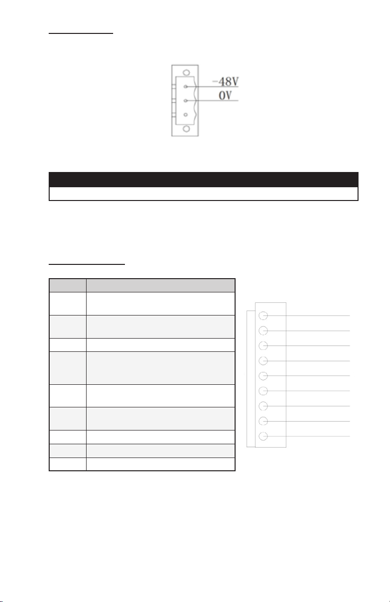
2.5 Power Input Cables .............................................................................................................6
2.6 Monitoring...........................................................................................................................7
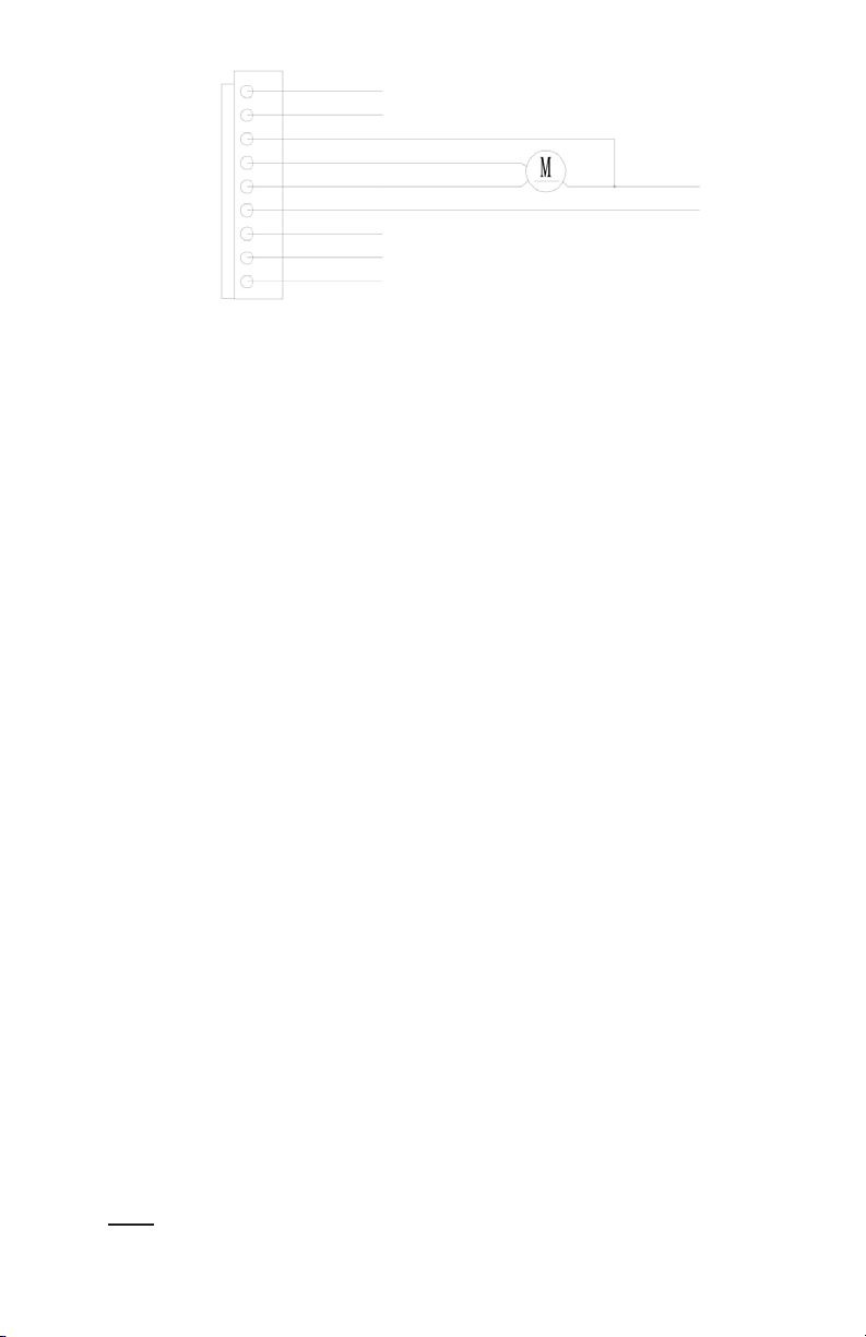
2.7 Hydrogen Discharge/Emergency Fan Connection (optional) .............................................7
2.8 Installation Checklist...........................................................................................................8
2.9 Startup .................................................................................................................................8
Chapter 3: System Function Introduction
3.1 Function...............................................................................................................................8
3.2 Operating Control Mode .....................................................................................................8
3.2.1 Cooling Control ......................................................................................................8
3.2.2 Heating Control.......................................................................................................9
3.3 Alarms .................................................................................................................................9
3.4 Hydrogen Discharging/Emergency Fan (optional) .............................................................9
3.5 Monitoring...........................................................................................................................9
3.6 Self Test.............................................................................................................................10
3.7 Operational Menu..............................................................................................................10
Chapter 4: Maintenance
4.1 Filter ..................................................................................................................................11
4.2 Fan.....................................................................................................................................12
4.3 Controller...........................................................................................................................12
4.4 Heater ................................................................................................................................12
4.5 Heat Exchanger .................................................................................................................12
4.6 Maintenance Checklist ......................................................................................................13
4.7 Disposal.............................................................................................................................13
Chapter 5: Troubleshooting
5.1 Troubleshooting Guide......................................................................................................13

ICE EX04-18 Heat I&O Manual 06/2020 Rev.1 4
Chapter 1: Description & Specifications
1.1 Foreword
Note: All operation of this unit shall be performed by qualified persons such as engineers
and technicians.
This manual shall only be used as the guide for the installation and operation of the ICE
EX Series Cabinet Climate Control Units. It introduces the installation, operation and
regular maintenance of the unit.
1.2 General Description
The EX Series heat exchanger is designed for outdoor telecommunication or control
cabinets. It is designed for easy installation and reliable operation. The heat exchanger can
be operated immediately after installation. And the output can be automatically adjusted
when internal heat load changes, any fault can be read remotely through the RS485 interface
monitoring system.
The EX Series heat exchanger works as shown in Figure 1, the unit’s internal loop draws
heated air from upper opening, the heat dissipated to the outside air in the heat exchanger.
The external loop draws cold air from lower end and discharges the hot air from the upper
opening.
Figure 1. Functional Diagram
IMPORTANT
The air conditioner shall be kept vertically strictly in accordance with the
instructions on the package during transportation, storage and use.
Power Input
DC input power: The normal operating voltage is -40 ~ -58V, The unit can be safely
operated between -38 ~ -60V.
AC input power: The normal operating voltage is 187~242V (50/60Hz), The unit can be
safely operated between 154~286V (50/60Hz).
Note: Please refer to the unit data label for the power input.
Application limitation
Ambient temperature: -40ºF~158ºF (-40ºC~70ºC)

5 ICE EX04-18 Heat I&O Manual 06/2020 Rev.1
1.3 Features
• High reliability
• Intelligent control
• Frequency regulated and energy-saving.
• Dry contact and RS485 intelligent communication interface
1.4 Standards
Standard Description
IEC61000-4 Electromagnetic Compatibility
IEC335-1 Safety of household appliances or similar electric appliance
GB4798.1 Environmental conditions existing in the application of electric
and electronic product – Storage
GB4798.2 Environmental conditions existing in the application of electric
and electronic product – Transportation
GB4798.3 Environmental conditions existing in the application of electric
and electronic product – Use
CE Third-party certication
Table 1. Applicable standards of products
Chapter 2: Installation & Operation
2.1 Unpacking and Inspection
All of the EX series heat exchangers are carefully packaged for shipping and storage.
Unpack the carton and remove the unit from the shipping materials. Check the packing
list to ensure all parts and components are present.
Note:
1. Please check for any damage to the packaging and units; if any is present, make a
note and inform Industrial Climate Engineering together with the bar code number
on the package within 7 days.
2. If the product will not be immediately installed or is to be forwarded to its final
destination, re-pack the unit and store it in a safe place.
3. As an environment concern, we recommend that all shipping cartons be recycled.
2.2 Preparation Before Installing
The cabinet should have filters for the external loop to prevent the dust from entering the
heat exchanger.
The external loop’s suction and discharging opening should be isolated. If the suction and
discharging air is short circuited, heat dissipation capability will reduced significantly.
The opening area of the cabinet should be at least 1.5 times of the heat exchanger’s inlet
and outlet opening area and directed toward the heat exchanger’s opening.
During normal operation, the heat exchanger’s external loop will draw in small amounts of
water. This water can be discharged from the heat exchanger by a drainage pipe. If the heat
exchanger is mounted inside the cabinet, the drainage pipe should be designed carefully,
and the pipe should not be twisted. And when the pipe is exposed to ambient lower than
32ºF (0ºC), care should be taken to prevent the pipe from freezing.

ICE EX04-18 Heat I&O Manual 06/2020 Rev.1 6
2.3 Mechanical Installation of the Heat Exchanger
Do not press on the heat exchanger cooling fins during installation - this will damage
them. If the heat exchanger fins are damaged, repair them before moving it. The
mounting flange is factory installed. Ensure the waterproofing seal is in place before
installing the unit.
2.4 Electrical Installation
The electrical installation of the air conditioner includes:
• Connecting the power cables
• Connecting the communication & alarm output cables
IMPORTANT
All the electrical connections should comply with the standards of the national
and local electrical codes. Please disconnect all the power supplies for the air
conditioner before the installation.
WARNING FIRE HAZARD
Improper adjustment, alteration, service, maintenance or installation could cause
serious injury, death and/or property damage.
Installation or repairs made by unqualied persons could result in hazards to
you and others. Installation MUST conform with local codes or, in the absence of
local codes, with codes of all governmental authorities have jurisdiction.
The information contained in this manual is intended for use by a qualied
service agency that is experienced in such work, is familiar with all precautions
and safety procedures required in such work, and is equipped with the proper
tools and test instruments.
The power connection should match the marking on the wiring, It is recommended that
the input circuit breaker be at least 16A.Some models’ temperature sensor is externally
located. Check to be sure the wiring input is correct and securely connected.
2.5 Power Input Cables
IMPORTANT
Please refer to the specific wiring definition mark on the unit.
AC Power Input:
If the unit needs AC input, will be an external AC input L, N, PE terminals access to the
corresponding position, as shown in Figure 2.1, please be sure to connect power supply
in accordance with instructions.
Figure 2. AC Power Input Wiring Diagram

7 ICE EX04-18 Heat I&O Manual 06/2020 Rev.1
DC Power input:
If the unit using -48V DC power input, the connection diagram is shown in Figure 2.2.
please be sure to connect power supply in accordance with instructions.
Figure 3. DC Power Input Wiring Diagram
2.6 Monitoring
IMPORTANT
Please refer to the specific wiring definition mark on the unit.
The heat exchanger provides normally open or normally closed alarm output dry
contacts, when the high temperature alarm, low temperature alarm, sensor failure alarm,
fan failure alarm and other faults are triggered, the output’s status changes.
For detailed information Please check the table 2.1 9PIN terminal definitions.
Monitoring Output:
The RS485 monitoring connector definition is following
Pin Denition
RS485+ RS485 communication ports (+) (up-
stream equipment monitoring interface)
RS485- RS485 communication ports (-) (up-
stream equipment monitoring interface)
4 GND
3
Door open alarm (Optional)/Hydrogen
discharging/emergency fan contact
input (Optional)
2Hydrogen discharging/emergency fan
alarm dry contact NC (Optional)
1Hydrogen discharging/emergency fan
alarm dry contact COM (Optional)
NC Public alarm dry nod (NC)
COM Public alarm dry nod (COM)
NO Public alarm dry nod (NO)
Table 2
9PIN Connection Interface
Figure 4.
9PIN Connection Interface
2.7 Hydrogen Discharge/Emergency Fan Connection (optional)
Notice: Contact capacity: max load 2A@48VDC.
Hydrogen discharge / emergency fan(DC input) connection interface diagram;

ICE EX04-18 Heat I&O Manual 06/2020 Rev.1 8
Figure 5. DC Input Connection Interface
2.8 Installation Checklist
Use the following checklist when the electrical connections and the heat exchanger
installation are completed.
1. Check the packing list to ensure no parts are missing.
2. No apparent obstacles near the interior and exterior air flow passages.
3. The heat exchanger is vertically mounted and all the mounting bolts are tightened.
4. Drainpipe is clear of obstructions.
5. Power input is reliable and correctly connected.
6. Alarm output is securely connected.
7. The input voltage is within the acceptable range.
8. Fan runs freely, with no abnormal noise.
2.9 Startup
After completing the Installation Checklist, the heat exchanger is ready for operation.
Close the circuit breaker and the unit will automatically begin operating. When the
temperature inside the cabinet rises above the preset value, the external fan will increase
to maximum speed.
Chapter 3: Operation
3.1 Function
The heat exchanger factory settings may be different from the default setting;
The heat exchanger is automatically controlled by interior temperature of the cabinet,
the controller measures the interior return temperature, compares it with the setting
value, then adjust the inner loop or outer loop fan speed to achieve the most reasonable
energy-efficient state of operation.
3.2 Operating control mode
3.2.1 Cooling Control
After power is applied, the inner fan will delay start. When inner temperature is above
77ºF (25ºC) and the internal temperature is higher than outside temperature it stops
when the internal temperature is below 75ºF (24ºC).
Note: The inner temperature is the temperature of return air heat exchanger cabinet.

9 ICE EX04-18 Heat I&O Manual 06/2020 Rev.1
Parameter Default Value Setting Range Units Description
Refrigeration Point 25 [15 ~ 50] ºC External fan stop point
CoolΔT 10 [6 ~ 30] ºC External fan setting range
Table 3. Cooling Set Point Parameters
3.2.2 Heating Control
Heating startup point = Heating on point - Heating sensitivity. In order to protect the
internal equipment, when the internal temperature below the heating on setting point,
the unit begins heating, when the cabinet temperature is higher than heating off point,
heater stops operating.
Parameter Default Value Setting Range Units Set Point Description
Heating
On Point 15 [10 ~ 20] ºC The temperature point of the
heating stop.
Heater
Sensitivity 10 [1 ~ 10] ºC The sensitivity of the
temperature control.
Table 4. Heating Set Point Parameters
3.3 Alarms
The Heat exchanger provides the following alarm information; monitoring software
can see the detailed alarm information, some models are equipped with warning lights
outside the unit.
Parameter Default Value Setting Range Units Description
High Temperature
Alarm 55 [25 ~ 80] ºC The temperature point of the
High Temperature alarm.
Low Temperature
Alarm 0 [-25 ~ 15] ºC The temperature point of the
Low Temperature alarm.
Table 5. Alarm Parameter Settings
3.4 Hydrogen Discharging/Emergency Fan (Optional)
The hydrogen discharging/emergency fan will provide automatic-cycle hydrogen
discharging according to the requirements of the environment inside the cabinet. The
interval between each automatic cycle hydrogen discharging is 24 hours (adjustable) and
the discharging time is 5 minutes (adjustable).
When the cabinet is over-temperature, a system failure occurs, or the external
temperature is low, the hydrogen discharging/emergency fan will be started to provide
forced ventilation.
3.5 Monitoring
The Heat exchanger is supplied with a RS485 control interface offers a variety of
information output. For detailed information, please refer to the protocol list.
If you need to adjust the set point, you can connect heat exchanger and computer with
RS485 ports, through the background monitoring software or handheld monitor to make
changes.
Note: To prevent unauthorized setting changes, make sure only qualified people are
permitted access.

ICE EX04-18 Heat I&O Manual 06/2020 Rev.1 10
3.6 Self-Test
The unit provides the self testing function for the onsite test. The self testing procedures
are as follows:
1. The indoor fan speed 50% run 30 seconds.
2. The indoor fan speed 100% run 30 seconds.
3. The external fan speed 50% run 30 seconds.
4. The external fan speed 100% run 30 seconds.
5. The external fan stops, if the optional electric heating, electric heating operates for
2 minutes.
6. Electric heating stops for 10 seconds, if the unit is equipped with the optional
emergency fan, the fan will run for 1 minute.
7. The unit then returns to normal operation.
3.7 Operational Menu Structure
The unit controller utilizes a 96x32 LCD, which contains 7 buttons for adjusting the
settings. The operation interface is as shown in the following figure.
ON/OFF ENTER ESC
Figure 6. Control Interface
ON/OFF: ON/OFF Button, (long press this button, about 4s) this can be used to turn
on/off the unit.
Up Button, which is used to select the previous record/menu or increase the
setting value (password only).
Down button, which is used to select the next record/menu or decrease the
setting value (password only).
Left button, which is used to increase the setting value during the parameter
setting or select the previous bit of the data during the password setting.
Right button, which is used to decrease the setting value during the parameter
setting or select the next bit of the data during the password setting.
ENTER: ENTER button, which is used to confirm the entry.
ESC: Quit button, which is used to return to the previous page menu.
If there is no keyboard operation for a continuous 60 seconds, it will automatically
return to the normal display interface.
When any button is pressed after the system is powered up, the backlight will turn on. If
there is no keyboard operation for a continuous 60 seconds, the backlight will turn off.

11 ICE EX04-18 Heat I&O Manual 06/2020 Rev.1
The factory default operation password of the unit is “0001”. To change it, press ENTER
on the normal display interface to enter the password input interface, press the LEFT
button or RIGHT button to select the digits to change, and press the UP/DOWN button
to change the relevant digits, and finally press ENTER button to confirm the change.
If the password is incorrect, the interface will display an error message, and the unit
setting cannot be changed. If the password is correct, you can enter the main menu and
edit the unit setting.
Note: The above diagram is unit menu structure, not the factory setting.
Chapter 4: Maintenance
WARNING
All maintenance shall be performed by qualied persons. Always disconnect the
power, communication and alarm output cables from the heat exchanger before
any maintenance and do not reconnect them until the maintenance is completed.
To maintain full performance of a heat exchanger operating in a harsh environment,
preventative maintenance should performed every six months.
Note: Make sure all the power input is shutoff before any maintenance work is done.
Tool lists:
1. Air compressor or a dedicated clean water gun
2. Brush
3. Cleaning towels
4. Screw driver
4.1 Filter
This heat exchanger has no filters; the cabinet provides air filtration. Any debris
blocking the openings will reduce air into the heat exchanger, thereby reducing its
performance.

ICE EX04-18 Heat I&O Manual 06/2020 Rev.1 12
4.2 Fan
If a fan fails, the fan can be replaced after dismounting the service panel. Using only
Industrial Climate Engineering spare parts to prevent any incompatibilities. Check the
weather seals after replacing the fan.
Service procedure:
1. Make sure all the power have been disconnected;
2. Dismantle the connector panel;
3. Dismantle the inner fan service panel;
4. Disconnect the connector of the fan; dismantle the fan with the frame;
5. Reverse the 2 and 3 steps to mount the new fan.
4.3 Controller
If the controller fails, ask for Industrial Climate Engineering’s standard spare parts, after
dismantling the service panel, the control board can be reached. Check the weather seals
after replacing the controller.
Service procedure:
1. Make sure all the power have been disconnected
2. Dismantle the inner fan
3. Disconnect the wiring of the controller
4. Dismantle the controller
5. Reverse the steps 2, 3,4 to mount the new controller
4.4 Heater (Optional)
If the heater fails, please contact Industrial Climate Engineering to order replacement
parts. Remove the installation of panels and fans; you can easily remove the fault heater.
Check the weather seals after replacing the heater.
In accordance with the following steps to replace the heater:
1. Be sure to close all of the circuit breakers
2. In accordance with instructions in section 4.2, remove the fan components
3. Remove heater wiring
4. Removal of the fixed heater screw
5. Follow the steps to the opposite of 2, 3, 4 steps to install a new heater and reinstall
the interior fan.
4.5 Heat Exchanger
If the heat exchanger is exposed to dirty ambient air, Use compressed air or clean water
to clean the heat exchanger, Note that before cleaning you must confirm that heater
power has been disconnected.

13 ICE EX04-18 Heat I&O Manual 06/2020 Rev.1
4.6 Maintenance Checklist
Date: ________________________ Maintenance Technician: ___________________
Equipment Type: ______________ Equipment Serial Number: __________________
Number Description Result Comment
1Input voltage is normal
2Sensor location is reasonable
3Filter is not dirty
4heat exchanger is not dirty
5Check whether there are loose all the lines
6Unit have no abnormal noise
7Fan have no unusual noise
8Drainpipe is not dirty block
Table 6. Maintenance Checklist
4.7 Disposal
DISPOSAL: Properly dispose of this product.
Chapter 5: Troubleshooting
5.1 Troubleshooting Guide
Symptom Possible Cause Solution
Unit Doesn’t Start
Power supply failure Check the external input power supply
Terminal is loose Check whether the connecting terminal is loose.
Power failure Check the DC input power voltage.
Fan Abnormalities
Power failure Check for loose wiring
Incorrect DC wiring Check the power input
High voltage Check the voltage
Bearing Replace the fan
Not Heating
Fuse triggered Check the fuse
No power Check input power
Heater failure Replace heater
Table 7. Troubleshooting Guide
This manual suits for next models
3
Table of contents
Other Airxcel Industrial Equipment manuals