SEI Industries Bambi Bucket BB1214 User manual

BAMBI BUCKET
Models 6072 –1821
SERVICE MANUAL
2019A

BAMBI BUCKET SERVICE MANUAL
Models 6072-1821
Version 2019A
PLEASE READ BEFORE USING.
This manual is applicable to the following models:
BB6072 (# 007144)
BB1214 (# 007148)
BB8096 (# 007145)
BB1214S (# 008738)
BB8096S (# 005702)
BB1518 (# 007149)
BB9011 (# 007146)
BB1518S (# 005708)
BB9011S (# 008737)
BB1821 (# 007150)
BB1012 (# 007147)
BB1821S (# 008739)
BB1012S (# 005705)
BB1821L (#011067)
Copies of this manual (#000506) are available from SEI.
This manual is also available on the SEI website.
Register for manual update notifications at bambiupdate@sei-ind.com
SEI INDUSTRIES LTD.
7400 Wilson Avenue
Delta, B.C. Canada
V4G 1H3
Phone: (604) 946-3131
Fax: (604) 940-9566
E-Mail: seisales@sei-ind.com
Website: www.bambibucket.com
COPYRIGHT © 2019 SEI INDUSTRIES LTD. ALL RIGHTS RESERVED

Version
Revision Summary
2019A
•General Revision

Table of Contents
Section 1: Introduction............................................................................................................ 1
Bambi System Drawing............................................................................................................................2
Dump Valve Operation.............................................................................................................................3
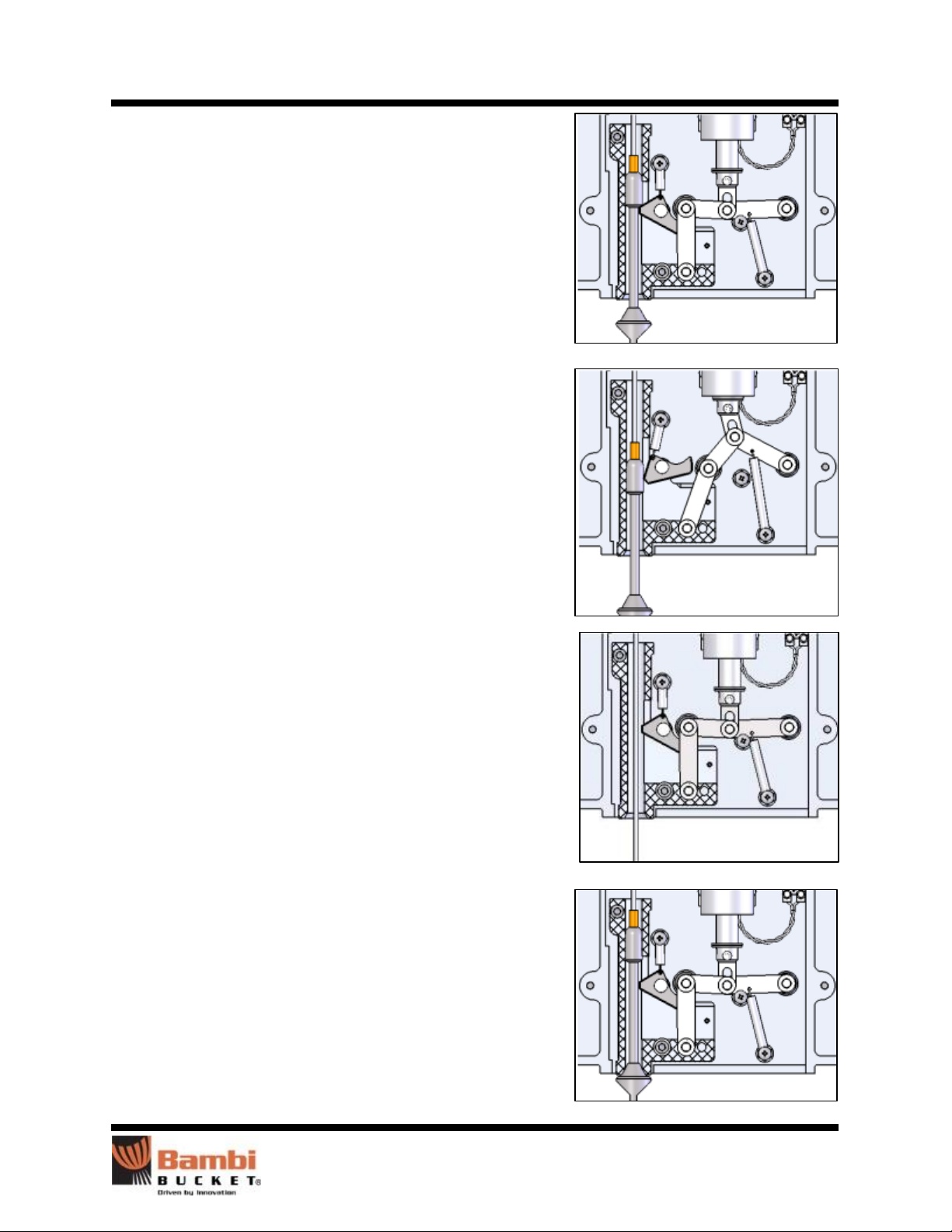
Control Head Operation............................................................................................................................4
Section 2: Deploying the Bambi Bucket................................................................................. 7
Attaching to the Cargo Hook....................................................................................................................7
Connecting Power.....................................................................................................................................8
Longlines ..................................................................................................................................................8
Checking Tail Rotor Clearance.................................................................................................................9
Instant Deployment System (IDS)..........................................................................................................10
Section 3: Accessories...........................................................................................................11
PowerFill Snorkel ...................................................................................................................................11
Foam Injection Systems..........................................................................................................................12
Section 4: Making Adjustments.............................................................................................13
Adjusting the Dump Valve Udder ..........................................................................................................13
Adjusting Purse Strings...........................................................................................................................13
Section 5: Packing and Storage.............................................................................................15
Packing the Bucket .................................................................................................................................15
Storing the Bucket...................................................................................................................................17
Section 6: Troubleshooting Guide.........................................................................................19
Valve Troubleshooting............................................................................................................................19
Control Head Troubleshooting................................................................................................................20
Section 7: Repair Assessment Guide....................................................................................23
Overview of Repair Categories...............................................................................................................23
Control Head Repair Criteria..................................................................................................................24
Cables Repair Criteria.............................................................................................................................25
M-Straps/Top Chains Repair Criteria.....................................................................................................26
IDS Repair Criteria.................................................................................................................................27
Bucket Shell Repair Criteria...................................................................................................................28
Cinch Strap Repair Criteria.....................................................................................................................29
Valve Repair Criteria..............................................................................................................................30

Section 8: Repairs...................................................................................................................31
Control Head Repairs..............................................................................................................................31
Rigging Repairs ......................................................................................................................................39
Valve Repair and Replacement...............................................................................................................45
Shell Repairs...........................................................................................................................................48
Section 9: Specifications and Parts.......................................................................................55
Capacity and Weight Specifications.......................................................................................................55
Parts ........................................................................................................................................................56
Section 10: Drawings..............................................................................................................72
Section 11: Warranty ..............................................................................................................76

Section 1: Introduction
Bambi Bucket Service Manual –Models 6072-1821 1
Section 1: Introduction
This manual provides information on the service and maintenance of Bambi Bucket models 6072 to 1821.
This service manual also includes all parts lists and installation drawings. A separate Bambi Bucket
operations manual is also supplied which should be carried on-board the helicopter.
For your own protection, and for longer bucket life, always read the instructions and warnings. Ignoring
these warnings could result in personal injury, bucket damage or aircraft damage.
SEI Industries Ltd. offers complete parts supply and repair services for the Bambi Bucket. For a repair
facility in your area, please contact SEI. For maintenance and repair purposes, parts diagrams and
descriptions are provided in this manual.
When you are ordering parts, please provide the model and serial number of your Bambi Bucket as shown
on the data tags located inside the bucket shell.

Section 1: Introduction
Bambi Bucket Service Manual –Models 6072-1821 2
Bambi System Drawing

Section 1: Introduction
Bambi Bucket Service Manual –Models 6072-1821 3
Dump Valve Operation
The Bambi Bucket uses a tubular fabric valve to control the
flow of water exiting the bucket. The lower end of the tube
has a flange which is attached to a circular opening in the
bottom of the bucket.
The upper opening of the tube is flattened and has a series of
grommets and purse strings laced alternately from each side.
The lower end of each string terminates in a washer and a
knot. Each string passes through a grommet in one side of the
tube, crosses the opening, and passes through a corresponding
grommet on the other side of the tube.
The upper ends of the purse strings are attached to a metal
ring. This ring is also attached to the riser cable.
When the riser cable is pulled upwards, it pulls the ring and
puts tension on the purse strings. This draws together the top
faces of the tube and a rubber layer below the grommets seals
the upper end of the tube.
When the bucket is dipped and filled with water, the water
pressure in the bucket presses on the outside of the tube and
reinforces the seal.
To open the valve, the tension on the riser cable is released,
allowing the riser, purse strings and valve tube to move
downwards due to the weight of the water in the bucket.
The valve tube turns inside out and extends below the bottom
of the bucket. The flattened end of the tube returns to a
circular shape allowing all the water to exit the bucket.
When all the water has exited the bucket, the riser cable pulls
the valve tube back to its starting position.

Section 1: Introduction
Bambi Bucket Service Manual –Models 6072-1821 4
Control Head Operation
The control head regulates the operation of the dump valve by raising and lowering the riser cable. The
upper end of the riser is attached to the lower end of the tripline assembly. The upper end of the tripline
is attached to the spring reel which winds the tripline onto a cable drum.
In the middle of the tripline is the bullet assembly. When there is no water in the bucket, the spring reel
winds up the tripline until the lower end of the bullet assembly reaches its limit on the bottom of the trip
block.
WARNING
Do not remove the cover on the control head while operating the Bambi Bucket. With the cover
removed, the tripline safety keeper is no longer functional. Without the safety keeper, the tripline
could separate and cause a tail rotor strike resulting in severe injury or death.

Section 1: Introduction
Bambi Bucket Service Manual –Models 6072-1821 5
When the bucket is filled with water, the pressure pulls down on
the valve, riser and tripline until the upper end of the bullet
assembly engages the mechanical catch. The mechanical catch
is locked in place by the linkage arms.
To dump the valve, an electrical signal is sent to the solenoid
which pulls up on the linkage arms and unlocks the catch.
The weight of water in the bucket pulls down on the valve, riser
and tripline. The upper end of the bullet assembly pushes past
the spring-loaded catch and the tripline unwinds from the spring
reel allowing the dump valve to fully open.
When the electrical signal to the solenoid is removed, springs
return the linkage arms, solenoid, and catch to their original
positions.
When all of the water has left the bucket, the only downward
force remaining on the tripline is the weight of the valve and
riser. This weight is overcome by the spring reel which winds up
the tripline, riser and valve.
As the bullet assembly re-enters the head, it pushes past the
spring loaded catch. The tripline continues to retract into the
spring reel until the lower end of the bullet assembly reaches its
limit on the trip block. The head is now latched and ready for
another fill.

Section 1: Introduction
Bambi Bucket Service Manual –Models 6072-1821 6
THIS PAGE INTENTIONALLY LEFT BLANK

Section 2: Deploying the Bucket
Bambi Bucket Service Manual –Models 6072-1821 7
Section 2: Deploying the Bambi Bucket
Attaching to the Cargo Hook
The Bambi Bucket is rigged for a lateral cargo hook. Correct attachment is indicated when the name
plate on the control head faces forward in flight. This ensures that the ballast on the Bambi will face
forward in flight.
Control Head Orientation
The control head has a moveable yoke which can be rotated
by 90°. The yoke is machined to orient in either direction. If
your helicopter has a longitudinal hook, rotate the shackle
yoke by 90°. This will place the name plate on the control
head forward in flight.
For this style of head, if using a swivel hook, always operate
in the locked position to assure that the ballast is always
facing forward in flight.
In some cases, where the cargo hook is too large for the
standard shackle, a second larger shackle can be used. If the
shackle is too large, it may cause the power cable to tangle,
pulling apart the breakaway plug.
WARNING
Ensure that all shackles are rated with a minimum safety factor of five for the gross weight of the
bucket as shown on the data plate.
CAUTION
The Bambi Bucket may not be suitable for a direct hook-up to the cargo hook. The actual hook-up will
be different for various aircraft and operators must comply with all instructions and bulletins supplied
by the aircraft manufacturer. It is the operator’s responsibility to ensure that the Bambi Bucket is
correctly fitted to the helicopter.

Section 2: Deploying the Bucket
Bambi Bucket Service Manual –Models 6072-1821 8
Connecting Power
The Bambi Bucket requires a 24 VDC power source capable of supplying 5 A.
There are four types of suggested wiring installations (see Section 10: Drawings):
1. Pilot control: The control is wired into the pilot’s control column through a relay.
2. Pilot control (US InterAgency): The control is wired into the pilot’s control column through
a 50 ampere relay as per US interagency regulations. This system can also be used to control
a heli-torch, etc.
3. Crew control: A crew member or pilot controls the dumping of the bucket using power from
the helicopter and a remote switch.
4. Crew control (remote power supply): A crew member or the pilot controls the dumping of
the bucket using a battery pack to supply the power to the remote switch.
The Bambi Bucket’s electrical supply is connected through a breakaway plug. The purpose of the plug is
to offer a clean “breakaway” if the Bambi Bucket has to be jettisoned from the aircraft in an emergency.
To ensure that wind action does not separate the plug, it is suggested that the plug be lightly taped
together with vinyl tape while in use.
To check for continuity in the connections, push the momentary contact switch. A clicking sound should
be heard from the control head.
NOTICE
To operate the solenoid and release the water, a momentary contact switch is used. The solenoid has a
10% duty cycle. Operating the solenoid continuously will result in solenoid failure.
Longlines
NOTICE
If using a longline, the minimum recommended length is 50 ft (15 m).
When using a longline, select the correct gauge of control cable from the following chart.
Wire Length
Wire Type
Connectors
Feet
Meters
Top
Bottom
0–100
0–30
14/2 SOW
NEMA 5-15P
NEMA 5-15R
101–200
30–61
12/2 SOW
NEMA 5-15P
NEMA 5-15R
When using a synthetic rope longline, it is recommended that a protective cover be used and the control
cable be inserted at the time of manufacture. However, if this is not feasible, it is recommended to secure
the cable using tape at 3 ft (1 m) intervals along the longline. It is not recommended to use zip ties as
they tend to damage the cover and longline. When attaching the control cable, allowances must be made
for any stretch in the load bearing line. When the control cable is taped to the outside of the longline, the
flight characteristics can change.

Section 2: Deploying the Bucket
Bambi Bucket Service Manual –Models 6072-1821 9
Checking Tail Rotor Clearance
WARNING
Using a Bambi Bucket with insufficient tail rotor clearance could result in a tail rotor strike which
could result in serious injury or death.
When a Bambi Bucket is attached directly to the helicopter cargo hook or attached using a longline less
than 50 ft (15 m) in length, it is important to confirm that there is adequate tail rotor clearance. Before
using the Bambi Bucket, check the tail rotor clearance.
1. Determine the tail rotor length by measuring the distance from the cargo hook to the closest
point on the helicopter tail rotor.
2. Determine the bucket overall length from the following chart:
Model
Overall Length
BB6072
12’- 11”
3.94 m
BB8096
14’- 6”
4.42 m
BB8096S
12’- 11”
3.94 m
BB9011
14’- 6”
4.42 m
BB9011S
12’- 11”
3.94 m
BB1012
14’- 6”
4.42 m
BB1012S
12’- 11”
3.94 m
BB1214
14’- 10”
4.52 m
BB1214S
13’- 3”
4.04 m
BB1518
15’- 2”
4.62 m
BB1518S
13’- 7”
4.04 m
BB1821
15’- 11”
4.85 m
BB1821S
14’- 5”
4.39 m
BB1821L
18’- 1”
5.51 m
Lengths are accurate to within 1%. Specifications subject to change.
If a firesock is used, add 8” (0.20 m) to the above dimensions.
To confirm the bucket overall length, stretch out the bucket on the ground, pulling the
suspension cables taut. Measure the distance from the shackle on the head to the bottom of
the extended dump valve. If a firesock is attached, measure to the bottom of the firesock.
3. The tail rotor clearance is equal to the tail rotor length minus the bucket overall length.
4. The tail rotor clearance must be a minimum of 6” (0.15 m).
If the tail rotor clearance is insufficient, shorter suspension lines, tripline, and deployment lines must be
used and can be ordered from SEI. Please specify the model and serial number when ordering parts.

Section 2: Deploying the Bucket
Bambi Bucket Service Manual –Models 6072-1821 10
Instant Deployment System (IDS)
The instant deployment system uses a hub and spoke
mechanism to automatically expand the mouth of the bucket
as soon as the weight of the Bambi Bucket is taken up by the
suspension cables.
When the bucket is full, the IDS deployment cable and IDS
restrainer cables should be slack as they should not bear any
load. Their function is to position the hub and spoke
mechanism to hold the bucket open.
To deploy the IDS on the ground, reach into the bucket, grasp
the hub of the IDS and pull outward fully until the two
restraining cables from the hub to the lower bucket shell are
tight.
The IDS restraining cables are set at the factory and normally
should not require any adjustment.

Section 3: Accessories
Bambi Bucket Service Manual –Models 6072-1821 11
Section 3: Accessories
PowerFill Snorkel
PowerFill Snorkel is a system which allows partial or complete
bucket fills from a range of previously inaccessible water sources as
shallow as 18” (0.46 m) including streams, ponds and low profile
dip tanks. It is available for bucket model 1821.
The PowerFill Snorkel is an externally mounted pump consisting of
a flange assembly and a pump assembly. The flange assembly is
permanently installed into the bucket and includes a flapper check
valve to prevent water from flowing back through the pump when
the pump is not running. Multiple flanges can be installed on a
number of buckets to accept the same pump unit.
The pump assembly is connected to the flange assembly with a
camlock fitting which allows the pump to be quickly removed for
ease of transport.
The PowerFill snorkel has an electrically driven pump with an optimum output of 425 USG/min (27 L/s).
The pumps require a 28 VDC power source capable of supplying 45 A. This supply must be from the
aircraft non-essential bus. The installation shall be done in accordance with FAA Advisory Circulars
AC43.13-1B and AC43.13-2A and any applicable aircraft manufacturer's instructions.
WARNING
Do not connect the PowerFill Snorkel system to any aircraft bus bar that is used for emergency or
essential loads. Before installation, do an electrical load analysis to ensure that the generator capacity
is adequate to operate the system and amend the aircraft electrical load to the new requirements.
Power is transmitted through a waterproof cable to the pump motor. At the top end of the cable, a quick
disconnect plug will separate with minimal force in the event of a load jettison. See the following chart
for recommended longline wire sizes for the PowerFill Snorkel.
Wire Length
Wire Type
Connectors
Feet
Meters
Top
Bottom
0–100
0–30
2 x #6 TEW
APP 6326G6
APP 6326G6
101–200
30–61
2 x #4 WELDING
APP 6326G6
APP 6326G6
The pump motor, impeller and housings are contained within a circular steel filter basket. The filter
basket serves to protect the components from impact damage while also acting as a debris screen.
The pump is fully waterproof in operation to a depth of 10 ft (3.0 m) and can run “dry” without damage.
It has a standard hydraulic grease nipple provision to extend the life of the motor output shaft seal.

Section 3: Accessories
Bambi Bucket Service Manual –Models 6072-1821 12
Foam Injection Systems
Sacksafoam is a foam injection system that uses a pump to dispense a controlled amount of foam
concentrate from a reservoir into the water in the bucket. The operation of the Sacksafoam is controlled
by the pilot through a control unit, which is mounted in the cockpit. There are two models of Sacksafoam
available depending on the location of the foam concentrate reservoir.
Sacksafoam Bladder
The Sackafoam Bladder uses a collapsible reservoir located in
the bucket. An internal check valve stops water from flowing
into the bladder and insures that foam is dispensed only while
the injection pump is operating. Because the foam in the
bladder displaces the water in the bucket, the total gross
weight is always constant.
The Sacksafoam bladder interfaces with the Sacksafoam
controller. Dispensing can be controlled directly from the
controller screen or a remote switch.
Bucket
Model
Part #
Reservoir Capacity
Gross Weight
Power
Imp Gal
USG
Liters
lb
Kg
BB8096
004338
10
12
45
113
51
5 A @
28 VDC
BB9011
BB1012
BB1214
BB1518
BB1821
See the following chart for recommended longline wire sizes for the Sacksafoam Bladder.
Wire Length
Wire Type
Connectors
Feet
Meters
Top
Bottom
0–100
0–30
14/2 SOW
NEMA 1-15P
NEMA 1-15R
101–200
30–61
12/2 SOW
NEMA 1-15P
NEMA 1-15R
Foam Compatibility
The Bambi Bucket is designed to be effective with foam. All materials used in the manufacture of the
Bambi Bucket are resistant to the chemical action of foam.
NOTICE
After using foam or retardant in the bucket, it should be washed with fresh water to remove all residue.
Foam and retardant can accelerate corrosion and degradation of materials if not removed.

Section 4: Making Adjustments
Bambi Bucket Service Manual –Models 6072-1821 13
Section 4: Making Adjustments
Adjusting the Dump Valve Udder
Udder refers to the amount that the dump valve bulges out
below the bucket shell, when the bucket is full. A properly
adjusted dump valve will have a maximum of 2" (50 mm) of
udder.
Too much udder will add to the volume and thus the weight of
the bucket. Too little udder will result in the valve leaking
and premature wear on the purse strings.
To adjust the udder, change the length of the tripline by
adjusting it at the tripline adjustment chain.
If a new tripline is installed, first install it at the same point on
the adjustment chain and then test the dump valve in use.
Remember to secure the adjustment shackle with a lock wire
or tie wrap first. It is impossible to judge udder with an empty
bucket on the ground.
Adjusting Purse Strings
Adjustment of the purse strings in the dump valve is important
to ensure a good seal at the neoprene lips of the valve mouth.
The purse string adjustment is set and tested at the factory.
The purse strings may shrink or stretch after use and require
adjustment.
Whenever new purse strings are installed, adjustments must
be made. When installing a new set of purse strings, orientate
the valve correctly and always make sure to stagger the strings
from side to side. See Section 8: Repairs for complete
instructions on how to replace purse strings.
When initially tying up the purse strings, note that more tension should be on the outside string with
progressively less tension towards the middle. If the tension is too great on the middle string, the valve
action will be sluggish when the valve is retracting.
Tripline
Adjustment
Chain

Section 4: Making Adjustments
Bambi Bucket Service Manual –Models 6072-1821 14
To adjust a single string:
1. Simply adjust the tension of the string to equal that of
adjacent strings. Repeat the knot shown three times
for each purse string.
To adjust all the strings:
1. Stand the bucket vertically.
2. With the valve bottom flat on the floor, pull the
bucket shell into a round shape by deploying the IDS.
3. Run a rope from an overhead support to the ring on
the top of the valve.
4. Proceed to adjust the strings.
Once the strings are adjusted, fill the Bambi Bucket with water, just below the top of the valve. Check to
see if both lips of the valve are matched right across the top. Sometimes, one lip will ‘track’ slightly
above or below the other.
Usually, one or two specific purse strings will cause this
improper tracking. To correct:
1. Grasp the purse strings at the centre of the lower side.
2. Pull the strings several times to bring the lip into
alignment.
3. Re-tie the purse strings so that the string is just snug.
Do not over-tension the string. Over-tensioning will
result in misalignment at another position on the
valve.

Section 5: Packing and Storage
Bambi Bucket Service Manual –Models 6072-1821 15
Section 5: Packing and Storage
Packing the Bucket
1. Collapse the IDS by pushing the hub into the bucket.
2. Grab the control head and pull the suspension lines
taut. Tape the lines together in two bunches.
3. Insert the operations manual into the storage bag.
4. Insert the control head into the storage bag.
This manual suits for next models
31
Table of contents
Other SEI Industries Other manuals