PowerMadd 34291 User manual

© 2018 PowerMadd M34291 Rev A
651-462-8465 www.powermadd.com
Star Series Turn Signal Kit
Installation Instructions for Part No. 34291
We thank you for purchasing the PowerMadd Star Series LED Turn signal light kit. This kit is intended to be
used with PowerMadd Star Series Handguards and model specific Handguard bracket kits for Harley Davidson
motorcycles. Installation should be installed by a certified Harley Davidson technician and the use of the
factory service Manual for proper installation. PowerMadd accepts no liability for damages caused by improper
installation.
Warning: Disconnect negative battery cable from battery before any work is performed. Refer to Harley
Davidson owner’s manual. Failure to do so may result in electrical shock, injury, or fire. Make sure to Secure
negative battery cable away from positive side of battery and all other positive voltage sources on the
motorcycle.
Wiring Diagram:
Note: Handguards and Bracket kits must be installed onto motorcycle before the Led light kit is
installed. Please refer to the handguard specific installation instruction.
STEP 1:
Start by removing the original vent cover from your Star series
handguards by first unsnapping the bottom three tabs from the
inside of each vent cover. Then pop the vent cover out from the
front side of the handguard.
STEP 2:
Drill a 7/16 hole in the inside corner of the star series handguard
as shown in Photo.
Install the LED light vent cover assembly by carefully feeding
the LED light wire through the vent hole that you previously
opened up. Take care when handling the LED Vent Cover.
Note: it is possible for the LED light to become detached. If this
happens, simply snap the LED light back into the vent cover.
Snap the LED vent cover in place by inserting the top three tabs
of the vent cover into the vent holes, next press on the bottom
front section to snap the lower three tabs into place.
Hardware Included:
1 –Pair Street LED vent covers
1 –LED module
4 –T-taps
4 –Space terminals
6 –Cable ties
4 –Small screws
Tools Required:
Drill
7/16” drill bit
Phillips screwdriver
4 –Small washers

© 2018 PowerMadd M34291 Rev A
651-462-8465 www.powermadd.com
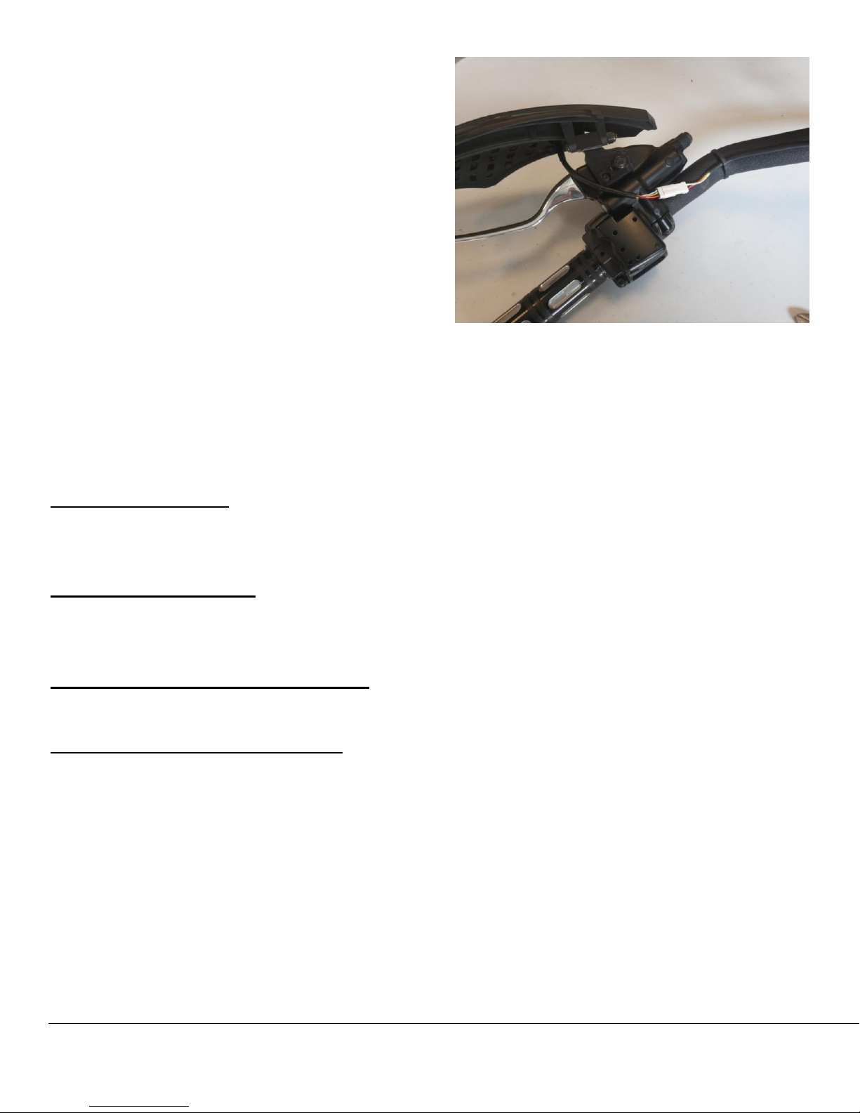
Optional: With the supplied #4 screw and flat washer,
secure the LED light vent cover to the handguard using
the two standoffs on the back of the vent cover. Do not
over tighten. These screws require only a small amount
of torque is required. Route LED light wires underneath
the handguard mounting bracket. Do not secure at this
time.
STEP 3:
Mount the LED module in an area that has a clean
surface, away from heat and so wires can move freely
without binding or fraying on sharp objects.
Wires from the LED module can be run on the outside of
the handlebars. If running wires on the inside of
handlebars we recommend removing the Male JST
connector from the 50“ wire lead to. Leave approximately 5” of the wire lead through the bar after you pulled
the wire through. Attach the male JST connecters back on the 50” wire lead (if wires are run through
handlebars).
STEP 4: Wiring
If using our turn signal eliminator kit. Part # (34292 or 34293) sold separately.
Follow the instructions as they are listed above and unplug the universal (4 wire) plug and install the Factory
turn signal eliminator kit as followed by the instruction sheet it provides. Simply plug and play.
Red wire labeled “+”
Determine the wire on your motorcycle you want to control the LED light. The best option is any running light wire.
Connect a supplied T-tap onto this wire. Crimp a spade terminal to the red wire labeled “+”. See T-Tap
instructions on page 3.
Ground wire labeled “-”
Tap into an existing ground wire, crimp a supplied spade terminal to the black wire labeled “-”. Once you have
found the ground wire to splice into, connect a supplied 3M T-tap onto the ground wire. See T-Tap
instructions on page 3.
Right turn signal wire labeled “right”
Tap into the white turn signal wire with a supplied 3M T-tap. See T-Tap instructions on page 3.
Crimp a spade terminal to the wire labeled “right”.
Left turn signal wire labeled “left”
Tap into the yellow turn signal wire with a supplied 3M T-tap. See T-Tap instructions on page 3
Crimp a spade terminal to the wire labeled “left”.

© 2018 PowerMadd M34291 Rev A
651-462-8465 www.powermadd.com
Connecting wires
•Find a safe location to secure the LED control box away from heat sources and impact damage. Best
location is behind the headligh Secure the LED control box using the supplied zip ties.
•Connect the two sets of LED light wires to the two sets of wires coming out of the LED module.
Reference Wiring Diagram for this section.
•Connect the red wire labeled “+” from the LED control box to the 3M T-tap on your hot wire.
•Connect the black wire labeled “-” from the LED control box to the ground source.
•Connect the wire labeled “right” to the right turn signal wire
•Connect the wire labeled “left” to the left turn signal wire
•Test your lights using the vehicles ignition switch and turn signal switch.
•Using the supplied zip ties secure all wires.
NOTE: These lights are COB (Circuit on board) LED Light strips and will require the use of a load equalizer if
model is Non can bus.
NOTE: Models with Can bus wiring do not require the use of a load equalizer.
NOTE: Module in this kit must be used in order for the lights to work properly. DO NOT install Led lights
directly to the factory turn signal connecters as for it will short out the LED light and warranty will be voided.
T-Taps Install Instructions:
1. Place wire in open channel of the T Tap.
2. Fold T Tap connector body until element contacts wire.
3. Crimp T Tap closed with pliers. Find a safe location to
secure the LED control box away from heat sources and
impact damage. Secure LED control box using supplied
zip ties.
For technical installation assistance contact:
Spadafora Chopper
781-324-1912
LIMITED WARRANTY
PowerMadd guarantees its products against defects in material and workmanship for a period of twelve (12) months from the original
date of purchase. POWERMADD shall not be liable for damage or injury caused by defective materials or workmanship.
POWERMADD may elect to repair or replace this product, but is the sole judge of any defects in their product. This warranty does not
cover any labor costs to remove or reinstall this product and is effect for one year from the original purchase date.
Table of contents
Popular Other manuals by other brands

Cansec
Cansec Invisible Reader installation instructions

Erreka
Erreka ULTRA Quick installation and programming guide

Ridgid Kollmann
Ridgid Kollmann K-75A Operator's manual

Balteco
Balteco TETRIS installation manual

Ultra Reef
Ultra Reef UKS-160 instruction manual

Holland
Holland FW0070 Installation, operation and maintenance