SEIKAKU PMG1000 V2 User manual
SEIKAKU TECHNICAL GROUP
LIMITED
APR.18.2015
5
A3 A4 A5
:
PMG 1000 V2 _V1.0
-RS
PMG1000 V2
0.028kg/1
NH00231 1:1
10
User's Manual
12 CHANNEL
POWERED MIXER

INDEX
12 CHANNEL POWERED MIXER
SAFETY RELATED SYMBOLS
WARNING
INTRODUCTION
01
02
04
03 IMPORTANT SAFETY INSTRUCTION
06
07
1
1
2
CONTROL ELEMENTS
3
TECHNICAL SPECIFICATION
4
16
05 3
FEATURES
* This unit can be used in following electromagnetic environment:
residential, commercial and light industrial, urban outdoors. It is the apparatus not intended
for rack mounting.
* F , the peak inrush current is 5.4A.
* F , the peak inrush current is 21.5A.
* exceeds limits given in EN 61000-3-2, it is necessary to agreed case by case
between manufacturer, installer or user on one hand and distribution network operator on
the other hand, to connect such equipment locally to the public low-voltage systems
* This device complies with part 15 of the FCC Rules. Operation is subject to the following two
conditions: (1)this device may not cause harmful interference, and (2)this device must accept
any interference received, including interference that may cause undesired operation.
Changes or modifications not expressly approved by the party responsible for compliance
could void the user's authority to operate the equipment.
NOTE: This equipment has been tested and found to comply with the limits for a Class B digital
device, pursuant to Part 15 of the FCC Rules. These limits are designed to provide reasonable
protection against harmful interference in a residential installation. This equipment generates,
uses and can radiate radio frequency energy and, if not installed and used in accordance with
the instructions, may cause harmful interference to radio communications. However, there is
no guarantee that interference will not occur in a particular installation. If this equipment does
cause harmful interference to radio or television reception, which can be determined by
turning the equipment off and on, the user is encouraged to try to correct the interference by
one or more of the following measures:
-- Reorient or relocate the receiving antenna.
-- Increase the separation between the equipment and receiver.
-- Connect the equipment into an outlet on a circuit different from that to which the receiver
is connected.
-- Consult the dealer or an experienced radio/TV technician for help.
or 700W Mixer
or 1000W Mixer
1000W Mixer
Power supply
Main voltage 220-240VAC 50/60Hz~
Fuse T6.3AL 250V
110-120V 50/60Hz~
T12AL 250V
temperature controlled 12V DC fam output
Over voltage protection
DC offset shutdown
Tape out 1K
All other out 120
DSP section (options)
A/D and D/A converters 24bit
Type of effects Echo ,Echo+Verb , Tremolo , Plate , Chorus ,Vocal
Rotary,SmallRoom,Flange+Verb,LargeHall
Controls Mute switch & Foot-switching with LED indicator
100 position preset selector(10 preseter * 10 variation)
FOOT-SW TIP:FX SLEEV:GND
Main mix section
Max. MAIN MIX output +22dBu XLR balanced (+16dBu un-balanced)
AUX range OFF to +15dB
Fader range OFF to +10dB
PHONES/CONTROL-ROOM range
OFF to +15dB
Hum&Noise <-75dB @ 20Hz~22KHz A-weighted all channel & MAIN
level:max; the other :minimum
Crosstalk
<-85dB @0dB 20Hz~22KHz A-weighted MAIN level:0dB,
the other :minimum
Power
section
Power continuous
(230V AC)
Power EIAJ 1KHz,
THD 1%
500W X 2 @ 4 both channel (at 1KHz RMS peak power,THD<1%)
300W X 2 @ 8 both channel (at 1KHz RMS peak power,THD<1%)
Power amplifiter section
650WX2@4 (ref.)
350W X 2 @ 8 (ref.)
Protection
Thermal
protection
Short protection
Limiter
over-temperature power limiting
thermal shutdown
short-circuit protection
overload output protection
clip limiter
permanent signal limiter
high frequency protection
mono ch <-75dB @20dB 20Hz~22KHz A-weighted MAIN level:0dB,
the other :minimum
<-89dB @0dB 20Hz~22KHz A-weighted MAIN level:0dB,
the other :minimum
<-79dB @20dB 20Hz~22KHz A-weighted MAIN level:0dB,
the other :minimum
stereo ch
1/4' TRS with balanced
+4dBu
Amp insert Insert
Sensitivity
17
TECHNICAL SPECIFICATIONS
SAFETY RELATED SYMBOLS
CAUTION
RISK OF ELECTRIC SHOCK
DO NOT OPEN
The symbol is used to indicate that
some hazardous live terminals are
involved within this apparatus, even
under the normal operating conditions.
The symbol is used in the service
documentation to indicate that specific
component shall be only replaced by
the component specified in that
Documentation for safety reasons.
Protective grounding terminal.
Alternating current /voltage.
ON: Denotes the apparatus turns on.
OFF: Denotes the apparatus turns off, bec-
ause of using the single pole switch, be sure
to unplug the AC power to prevent any
electric shock before you proceed your
service.
WARNING: Describes precautions that
should be observed to prevent the danger
of injury or death to the user.
CAUTION: Describes precautions that
should be observed to prevent danger of the
apparatus.
WARNING
Power Supply
Ensure the source voltage matches the
voltage of the power supply before turning
ON the apparatus.
Unplug this apparatus during lightning
storms or when unused for long periods
of time.
External Connection
The external wiring connected to the output
hazardous live terminals requires installation
by an instructed person, or the use of ready-
made leads or cords.
Do not Remove any Cover
There are maybe some areas with high
voltages inside, to reduce the risk of electric
shock, do not remove any cover if the power
supply is connected.
The cover should be removed by the qualified
personnel only.
No user serviceable parts inside.
Fuse
To prevent a fire, make sure to use fuses
with specified standard (current, voltage,
type). Do not use a different fuse or short
circuit the fuse holder.
Before replacing the fuse, turn OFF the
apparatus and disconnected the power
source.
Protective Grounding
Make sure to connect the protective
grounding to prevent any electric shock
before turning ON the apparatus.
Never cut off the internal or external pro-
tective grounding wire or disconnect the
wiring of protective grounding terminal.
Operating Conditions
Hazardous live terminal .
Disposing of this product should
not be placed in municipal waste
and should be separate collection.
This apparatus shall not be exposed to
dripping or splashing and that no objects
filled with liquids, such as vases, shall be
placed on this apparatus.
1
16
12 CHANNEL POWERED MIXER
2-TACK IN
Distortion(THD+N)
mono channel
+/-15dB @12KHz
+/-15dB @2.5KHz
+/-15dB @80Hz
RCA jack
20Hz to 22KHz,+/-1dB
<0.03% at +0dB ,22Hz~22KHz A-weighted
High
Mid
Low
stereo channel
+/-15dB @12KHz
+/-15dB @2.5KHz
+/-15dB @80Hz
TAPE IN
Frequency response
Gain range OFFto15dB
Stereo input channels
Mic input
LOW CUT
Channels EQ
XLR with balanced
75Hz
20Hz to 22KHz,+/-1dB
<0.03% at +0dB ,22Hz~22KHz A-weighted
-20dBu~ +20dBu
<-105dBr A-weighted
Line input 1/4' TRS or TRS/RCA with un-balanced
COMPRESSOR GAIN:0---->9dB
THRESHOLD:20dB---> 5dB
MODEL :
Microphone input
Gain range
Max. Input
SNR
Phantom power
Distortion(THD+N)
Sensitivity range
PMG1000 V2
XLR with balanced
20Hz to 22KHz,+/-1dB
<0.03% at +0dB ,22Hz~22KHz A-weighted
0dBto50dB
+20 dB (balanced)
<0.03% at +0dB ,22Hz~22KHz A-weighted
+15dB~ -35dB
+48V with switch control
1/4' TRS with balanced
20Hz to 22KHz,+/-1dB
<-105dBr A-weighted
Mono channels
Frequency response
Distortion(THD+N)
Line input
Frequency response
Frequency response
Distortion(THD+N)
Sensitivity range
SNR
AUX RETURNS
1/4' TRS with un-balanced
Input
20Hz to22KHz,+/-1dB
Frequency response
<0.03% at +0dB ,22Hz~22KHz A-weightedDistortion(THD+N)
OFF TO +15dB
GAIN range
<-100dBr A-weighted
SNR
Impedances
Microphone input 1.8K
All other input 10K or greater
2
Servicing
Refer all servicing to qualified personnel. To
reduce the risk of electric shock, do not
perform any servicing other than that
contained in the operating instructions unless
you are qualified to do so .
Servicing is required when the apparatus has
been damaged in any way , such as power
supply cord or plug is damaged , liquid has
been spilled or objects have fallen into the
apparatus, the apparatus has been exposed
to rain or moisture , does not operate
normally, or has been dropped.
To reduce the risk of fire or electric shock,
do not expose this apparatus to rain or
moisture.
Do not use this apparatus near water.
Install in accordance with the manufacture-r's
instructions. Do not install near any heat
sources such as radiators, heat registers,
stoves, or other apparatus (including am-
plifiers) that produce heat. Do not block
any ventilation openings.
IMPORTANT SAFETY INSTRUCTIONS
Read these instructions.
Keep these instructions.
Heed all warnings.
Only use attachments/accessories spec-
ified by the manufacturer.
Power Cord and Plug
Do not defeat the safety purpose of the
polarized or grounding type plug.
A polarized plug has two blades with
one wider than the other. A grounding
type plug has two blades and a third
grounding prong. The wide blade or the
third prong are provided for your safety.
If the provided plug does not fit into your
outlet, consult an electrician for replace-
ment of the obsolete outlet.
Protect the power cord from being walk-
ed on or pinched particularly at plugs,
convenience receptacles, and the point
where they exit from the apparatus.
Cleaning
When the apparatus needs a cleaning, you
can blow off dust from the apparatus with
Follow all instructions.
No naked flame sources, such as lighted
candles, should be placed on the apparatus.
a blower or clean with rag etc.
Don't use solvents such as benzol, alcohol,
or other fluids with very strong volatility and
flammability for cleaning the apparatus body.
Clean only with dry cloth.
The mains plug is used as the disconnect device,
the disconnect device shall remain readily
operable.
15
12 CHANNEL POWERED MIXER
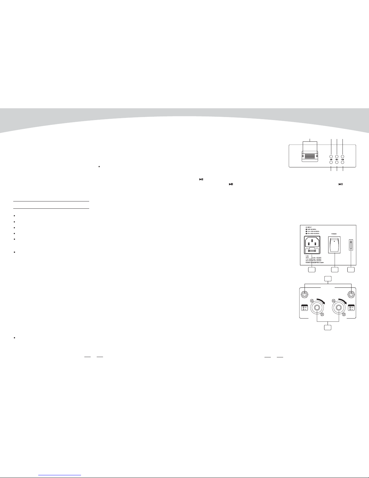
ThisbuttonisusedtoturntheMainPoweronandoff.
it is a output jack for connect with the AMP. Note: the
MAX. OUTPUT:
The Left and Right AMP Insert jacks are used for power AMP balanced phone inputs.
When not using the input phones, the signal path is normal (from master output to internal amplifier.
When inserting a phone plug, the signal path gets split up between the master output and internal
power amplifier, which allows customers to operate the internal power amp via this power amp
inputs.
46.
47. POWER ON / OFF
48. PHANTOM ON / OFF
AMP OUTPUT
50. AMP Insert(Left/Right)
This switch will apply +48V phantom power only to
the 6XLR inputs sockets. When these XLR sockets are
connected with devices that do not require phantom
power, please make sure the phantom power is turned
off. Otherwise, this may damage the device and mixer.
49.
Press VOL- key to decrease volume during
Power on state. The default factory setting
is maximum.
Press VOL+ key to increase volume during
Power on state.
In play state, press PLAY / PAUSE key to pause the player. In pause state, press PLAY /
PAUSE key to start playing.
Press this key and hold for 2-3 seconds, the player will change to matching state. In this sate,
the two LEDs alternately flash quickly, and you can u se your mobile phone, tablet or
PC Bluetooth adapter to find devices, BT-2.1. If your device's Bluetooth version lower than
2.0, you should enter the password "0000". If your device's Bluetooth version higher than 2.0,
you do not need to enter a password.
Use it to connect your mixer to the main AC with the
supplied AC cord.
2X500W@4Ohms 2X300W@8Ohms
MIN.LOAD:4 Ohms CLASS 2 WIRING WAY BE USED
d- VOL-
e- VOL+
f- PLAY/PAUSE
g- PAIR
AC INLET WITH FUSE HOLDER
SBT-2.1
VOL+ PAI R
VOL-
Bluetooth Audio Interface
(e)
(f)(a) (c)
(d)
(b)
(g)
46
ON
OFF
+48V
Use only with a 250V fuse
47 48
49
MAX. OUTPUT: 2 X 500W@ 4 Ohms 2 X 300W@ 8 Ohms
MIN.LOAD:4 Ohms CLASS 2 WIRING WAY BE USED
RL
AMP INS.
AMP section
AMP INS.
RIGHT LEF T
50
INTRODUCTION
3
14
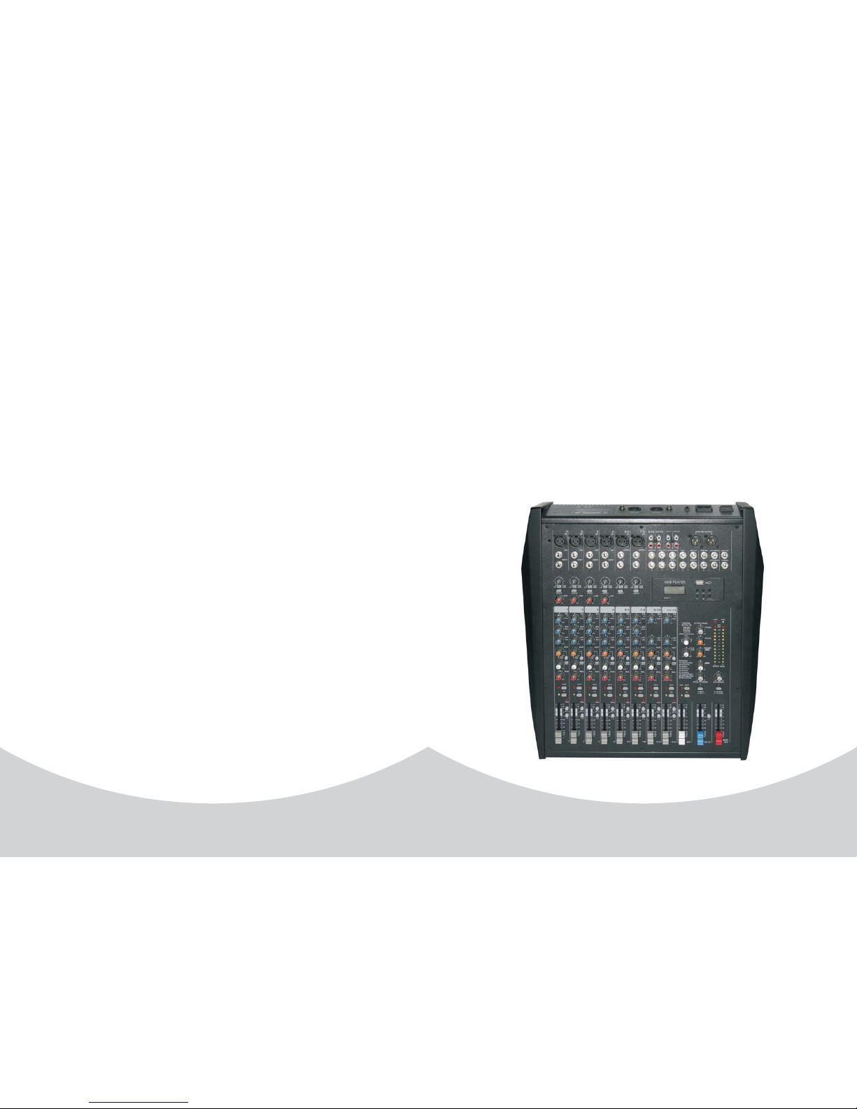
Thank you choosing for purchasing 12 Channel powered Mixer . This is a professional
compact mixer to give you great quality and better reliability than ever before You will get
the smooth, accurate more natural and open sound from this apparatus. and it is really ideal
for gigs, recording and fixed PA installations.
The 12 Channel powered Mixer is packed with features that can not be found in other
consoles of its size: 4mono (provided with ultra low noise microphone pre amplifiers and
Phantom Power at +48 Volt ) and 4 stereo input channels and each of them is provided with
a 3-band equalizer for HI, MID and LOW controls, as well as 2 auxiliary control; highly
accurate 12-segment bar graph meters and 2-track inputs assignable to main mix, control
room/phones Outputs etc..
This unit is very easy to operate but we advise you to go through each section of this manual
carefully. In this way you will get the best out of your 12 Channel powered Mixer.
FEATURES
Ultra-low noise discrete MIC Preamps with +48V Phantom Power.
4 MIC Input Channels with XLRs and balanced Line Inputs and Insert I/O and
Compressors control
Low Cut for each MIC Input
2 Stereo Input Channels with mono XLRs Input and TRS Jacks; 2 Stereo Input Channels
with RCA Jacks and TRS Jacks.
3-band EQ and Peak LEDs on each MIC channels. 2-band EQ and Peak LEDs on Stereo
channels.
1 AUX Sends POST/PRE per channel for monitoring or external effects.1 DFX(AUX) Sends
POST Fader for internal effects or monitoring.
Mute and PFL function for each channels, 60mm Fader for level control.
GR1/2 and Main L/R bus assign for each channel
2-Track Input assignable to Main Mix or Control Room / Headphone Outputs.
Balanced XLR & TRS outputs for Main Mix
Built in 24-bit DSP effect with 100 presets.
Option MP3 player or Bluetooth player.
Built in high-powered CLASS-D amplifier module , Rated power:
2 x 500W@ 4 or 2 x 300W@ 8 .
2 x 650W@ 4 or 2 x 350W@ 8
ÙÙ
ÙÙ
(at 1KHz RMS peak power,THD<1%)
(ref. EIAJ)
12 CHANNEL POWERED MIXER
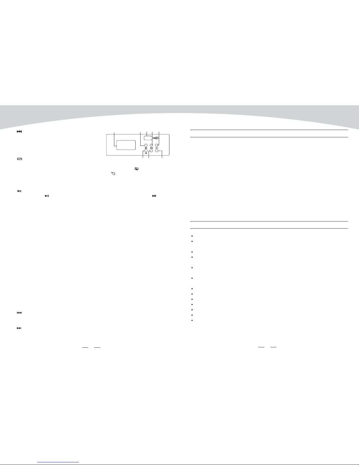
In pause state, press this key, it will go to
next track and keep in pause state. In play
state, press this key, it will go to the next
track and start playing.
Press this key, the player will change between the following four modes:
REP ALL means to repeat all tracks in the memory, mark on the screen is
REP1 means to repeat one track, the mark on the screen is
Play in order means to play the tracks according to the order, the mark on the screen is blank.
Random play means to play the tracks at random, the mark on the screen is A.
All the USB player information are monitored through this sexy & magic display.
an be paired with mobile phones, tablets or PC Bluetooth adapter to play stereo audio with
two LED status indicator.
These two LEDs use to display different working state:
1). For the first time that module power on,it is on stand by state, and the right LED flashes
twice about 2 seconds once.
2). Matching state, two LED's alternately flash quickly.
3). After connected the device, the right LED lighted on constantly.
Press this key, it will go to the previous track and start playing.
Press this key, it will go to the next track and start playing.
c- NEXT
d- RPT
-
g
Bluetooth Version 2.1
C
a-Display
b- PRE
c- NEXT
e- PLAY/PAUSE
fREC
- POWER(Push & Hold)
Option Four -
In play state, press PLAY / PAUSE key to pause the player. In pause state, press PLAY /
PAUSEkey to start playing.
In power on state, press this key, it will go to the recording preparation state. Press REC again
to start recording. Any other operations are not available in recording state until press POWER
to stop recording;
When the unit is off, press this key and hold for about 2 or 3 seconds to turn on the power
supplyofplayer.Repeattheaboveoperation,youcanturnoffthepowersupplyoftheplayer.
h- DISPLAY:
USB PLAYER
SMP-R
(Push & Hold)
POWERREC
(e) (f)
(a)(h) (c) (d)(b)
(g)
413
12 CHANNEL POWERED MIXER
CONTROL ELEMENTS
In pause state, press this key, it will go to next track and keep in pause state. In play state, press
this key, it will go to the next track and start playing.
Press this key, the player will change between the following four modes:
REP ALL means to repeat all tracks in the memory, mark on the screen is
REP1 means to repeat one track, the mark on the screen is
Play in order means to play the tracks according to the order, the mark on the screen is blank.
Random play means to play the tracks at random, the mark on the screen is A.
c- NEXT
d- RPT
In play state, press PLAY / PAUSE key to pause the player. In pause state, press PLAY /
PAUSEkey to start playing.
e- PLAY/PAUSE
f- STOP
In play state, press this key to stop playing and all the songs in USB memory will appear on the
display; In stop state, press STOP / PRE/ NEXT keys again to go to first song and the
player will keep in pause state, then press PLAY/PAUSE key to play the song.
g- POWER(Push & Hold)
h- DISPLAY:
NOTE: basic interface instruction
Option Three - SMP-R
a- USB PORT
b- PRE
When the unit is off, press this key and hold for about 2 or 3 seconds to turn on the
power supply of player. Repeat the above operation, you can turn off the power supply of the
player.
All MP3 player information are monitored via this sexy & magic display.
When the player isn't connected to a USB memory equipment,
theinterfaceisasfollows:
When the player is searching for USB tracks, the interface is as
follows:
When the player is in pause state, the interface is as follows:
When the player is in use, the interface is as follows:
The file system of USB memory for USB players is FAT16 and FAT32, and these players can
only decode MP3. It has 7 rank subordinate folders at most.
For connecting with USB memory.
In pause state, press this key, it will go to previous track and keep in pause state. In play state,
press this key, it will go to the previous track &start playing.
MAIN MIX OUTPUT
2TK IN 2TK OUT
L
R
RR
L(MONO) LGR2 OUT LDFX SENDS PHONES
AUX SENDS
MAIN MIX
GR1 OUTCTRL.
ST RETURNS
R
FOOT SW
LR
AMP Lim.
L
R
PAN PAN PAN PAN BAL BAL BAL BAL
MUTE
PFL
PEAK
MUTE
PFL
MUTE
PFL
MUTE
PFL
MUTE
PFL
MUTE
PFL
MUTE
PFL
MUTE
PFL
MUTE
PFL
PEAK PEAK PEAK PEAK PEAK PEAK PEAK
PEAK
12345/6 7/8 9/10 11/12 GR 1-2
MAIN
MIX
DFX
DFX
POST
DFX
POST
DFX
POST
DFX
POST
DFX
POST
DFX
POST
DFX
POST
DFX
POST
POST
PRE
AUX AUX AUX AUX AUX AUX AUX AUX
EQ
HI
EQ
HI
EQ
HI
EQ
HI
EQ
HI
EQ
HI
EQ
HI
EQ
HI
LOW LOW LOW LOW LOW LOW LOW LOW
MID MID MID MID MID MID
1 2 3 4 5/6 7/8 9/10 11/12
LOW CUT LOW CUT LOW CUT LOW CUT LOW CUT LOW CUT
TO MAIN
TO AUX
AUX
SENDS
DFX
MAIN
G1-2R
OUTPUT LEVEL
10
4
0
7
10
20
30
LR
CLIP
7
2
4
2
48V PWR
DIGITAL
EFFECTS
PROGRAM (PUSH)
FX TO
AUX
00 09 Echo
10 19 Echo Verb
20 29 Tremolo
30 39 Plate
40 49 Chorus
50 59 Vocal
60 69 Rotary
70 79 Small Room
80 89 Flange Verb
90 99 Large Hall
MIC
4
LINE
INSERT
MIC MIC
5/6 7/8
L(MONO) L(MONO)
RR
9/10
MIC
1
LINE
INSERT
MIC
2
MIC
3
LINE
INSERT
LINE
INSERT
RR
LL
LINE 11/12
LINE 9/10
11/12
L
R
GR1 2
LR LR
GR1 2 GR1 2
LR LR
GR1 2 GR1 2 GR1 2 GR1 2 GR1 2
LR LR LR LR LR
R/2L/1
15
10
dB
5
0
5
10
20
30
40
60
COMP
010
COMP
010
COMP
010
COMP
010
15
15
0
15
15
0
15
15
0
15
15
0
15
15
0
15
15
0
15
15
0
15
15
0
15
15
0
15
15
0
15
15
0
15
15
0
15
15
0
15
15
0
15
15
0
15
15
0
15
15
0
15
15
0
15
15
0
15
15
0
15
15
0
15
15
0
15 15 15
15 15 15 15
15 15
15 15 15
15 15 15
15
0
15
0
15
0
15
0
15
0
15
10
dB
5
0
5
10
20
30
40
60
15
10
dB
5
0
5
10
20
30
40
60
15
10
dB
5
0
5
10
20
30
40
60
15
10
dB
5
0
5
10
20
30
40
60
15
10
dB
5
0
5
10
20
30
40
60
15
10
dB
5
0
5
10
20
30
40
60
15
10
dB
5
0
5
10
20
30
40
60
15
10
dB
5
0
5
10
20
30
40
60
15
10
dB
5
0
5
10
20
30
40
60
15
10
dB
5
0
5
10
20
30
40
60
15
0
15
0
0
15
50dB
35dB
MIC
LINE
0
15
50dB
35dB
MIC
LINE
0
15
50dB
35dB
MIC
LINE
0
15
50dB
35dB
MIC
LINE
0
20
40dB
20dB
MIC
LINE
0
20
40dB
20dB
MIC
LINE
R/2L/1 R/2L/1 R/2L/1 R/2L/1 R/2L/1 R/2L/1 R/2L/1
POST
PRE
POST
PRE
POST
PRE
POST
PRE
POST
PRE
POST
PRE
POST
PRE
12KHz
2.5KHz
80Hz
12KHz
2.5KHz
80Hz
12KHz
2.5KHz
80Hz
12KHz
2.5KHz
80Hz
12KHz
2.5KHz
80Hz
12KHz
2.5KHz
80Hz
12KHz
80Hz
12KHz
80Hz
CTRL./PHONES 2TK IN/MP3
ST RETURNS
15
TO MAIN
TO CTRL.
AMP
Pmg1000
12 - CHANNEL POWERED MIXER
88

5
12
12 CHANNEL POWERED MIXER
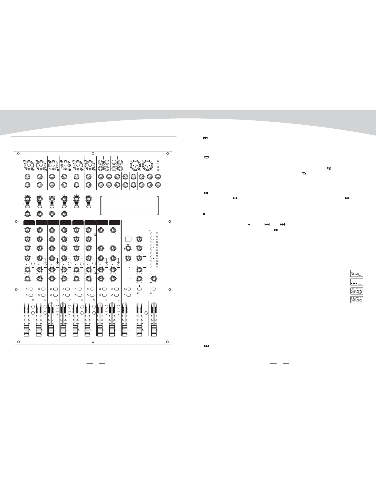
1.Mono MIC/LINE
2.STEREO INPUT
. INSERT JACKS
. GAIN CONTROL
You can connect balanced, low impedance microphones or
a low level signal to the XLR socket. On the 1/4'' LINE jack
you can connect either a microphone or a line level
instrument such as synthesizers, drum machines, effect
processors or any other line level signal.
Note: you shall never connect an unbalanced microphone
to the XLR socket if you do not want to damage both the
microphone and mixer. Also, it is not possible to
simultaneously use both the MIC & LINE inputs
on the same channel, use only one of them for the
appropriate source.
They are organized in stereo pair and provided with 1/4"
TRS sockets. Use the left input if connect a mono input
signal to the STEREO INPUT.
3
Each of these jacks provides an insert point between the equalizer and level control of
the corresponding input channel, The INSERT jacks can be used to independently connect
devices such as graphic equalizers, compressors, or noise filters into the corresponding
channels. These are TRS phone jacks that carry both the send and return signal.
4
5
By pressing this button you will activate a 75Hz low frequency filter with a slope of 18dB per
octave. You can use this facility to reduce the hum noise infected by the mains power supply.
Or the stage rumble while using a microphone.
6
Adjust the amount of compression applied to the channel. Turn the knob to the right to increase
the compression ration and the output gain will automatically adjusted. The result is smoother,
more even dynamics because louder signals are attenuated which the overall level is boosted.
.LOWCUT
.COMP CONTROL
Adjusts the input signal level. To achieve the best balance between S / N and dynamic range,
adjust the level so that the peak LED indicator lights occasionally only on the highest input
transients. For mono channel the MIC input adjustment range of the Gain is 0 to 50dB and the
sensitivity of line input is +15 to -35dB; For stereo channel the MIC adjustment range of the
Gain is 0 to 40dB and the sensitivity of line input is +20 to -20dB.
LOW CUT LOW CUT
COMP
010
0
15
50dB
35dB
MIC
LINE
0
20
40dB
20dB
MIC
LINE
4
5
6
MIC
4
LINE
INSERT
MIC
5/6
L(MONO)
R
1
2
3
Fig 6
Fig 7
03. Plena pop 04.mp
02. Plena pop 06.mp
01. lena pop 02.mp3
[.]00:20
3). The display will show the following interface. Press the PRE / NEXT key,
you can select the starting song, then press the PLAY/PAUSE key, the selected
song playback will start. Press PLAY / PAUSE key again, or press STOP key,
the play back will stop. Press PLAY / PAUSE key again, or press STOP
key, the playback will start again from the same point. Twice press STOP, the
USB player will return to Fig 3 interface.
d)-"Program" mode
1). In Fig 2, select "Program" to enter into the following
interface: " Play list Set ": Set the playing list."Playing
List": Play list. Press PRE/ NEXT key to select,
press STOP key to return the Fig2 interface.
2). After entering into the "Play List Set", the display will
show as Fig3. Selecting the desired folder, the
display will show the following interface. The display
will show all the MP3 files, the selected song will be
inserted into the playing list and a mark will appear.
Press again you're going to delete the song from the
playing list, and the mark will disappear. Press the
STOP key, you will return to Fig 2 interface. The playing list can accept up to 20 songs,
and it will display the list according to song insert order.
e
PLAY / PAUSE key
)-Folder List:
See the Fig 3, the display shows MP3 files folders names. Use PRE/ NEXT key to
scan, press , you'll enter into corresponding folder. In order to
return to Fig5 interface, you just need to press the STOP key.
Option Two - SMP-T
The file system of USB memory for USB players is FAT16 and FAT32, and these players can
only decode MP3. It has 7 rank subordinate folders at most.
a- USB PORT
b- PRE
For connecting with USB memory.
In pause state, press this key, it will go to
previous track and keep in pause state. In play state, press this key, it will go to the previous
track & start playing.
USB PLAYER
SMP-T
(Push & Hold)
POWER
(e) ( f )
(a)(h) (c) (d)(b)
(g)
In pause state, press this key, it will go to next track and keep in pause state. In play state, press
this key, it will go to the next track and start playing.
c- NEXT
11
6
12 CHANNEL POWERED MIXER
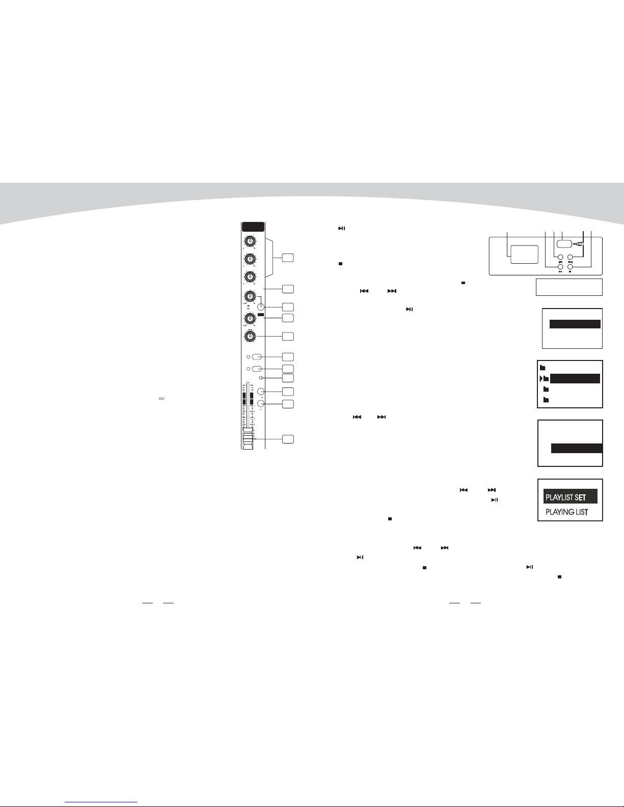
This is the treble control. You can use it to get rid of high
frequency noises or to boost the sound of cymbals or the high
harmonics of the human voice. The gain range goes from -15dB
to +15dB with a center frequency of 12kHz.
This is the mid range control. It can affect most fundamental
frequencies of all musical instruments and human voice. An
attentive use of this control will give you a very wide panorama
of sound effects. The range goes from -15dB to +15 dB and the
center frequency of 2.5kHz.
This is bass control . it is used to boost male voice, kick drum
or bass guitar. The gain range goes from -15dB to +15dB with
a center frequency of 80Hz.
These controls are used to adjust the level of the signal sent to
AUX buses, and their adjustable range is from - to +15dB
Each channel is equipped with the PRE/POST button, pressing
this button the signal can be assigned to PRE / POST-FADER.
The PAN control determines the stereo positioning of the channel signal on the stereo L and
R buses.
The BAL control knob sets the balance between left and right channels. Signal input through
the stereo L/R bus.
Each channel is equipped with the MUTE button, pressing this button is equal to turning the
fader down, which can mute the corresponding channel output except for the PRE AUX sends,
channel INSERT send and SOLO (in PFL mode), and the MUTE LED will illuminate.
Each channel is equipped with the PFL button, pressing this button which the corresponding
AUX send will be routed to CTRL ROOM/PHONES outputs and METER display.
7. EQUALIZER
Hi
MID
Low
8. AUX
9. PRE/POST
12. MUTE
13. PFL
.
10. DFX / POST
11. PAN / BAL CONTROL.
These controls are used to adjust the level of the POST FADER signal sent to DFX (AUX) SENDS
output, which can be used for monitor application and effects & sound processors input.
PAN
MUTE
PFL
PEAK
1
DFX
POST
POST
PRE
AUX
EQ
HI
LOW
MID
1
GR1 2
LR
15
R/2L/1
15
10
dB
5
0
5
10
20
30
40
60
15
15
0
15
15
0
15
15
0
15
12KHz
2.5KHz
80Hz
7
8
9
10
11
12
13
15
14
16
17
FOLDER:
pop music
jazz music
classic music
Fig 3
b- Inserted the USB key, the USB player starts to search the
songs in USB key, and the display shows "Searching". At the
end of the search, the display will show as Fig. 2.
Using PRE / NEXT keys, you can select one of following
three menu options ("Playing", "Program" and "Folder List").
Press Playing, the unit will enter into the corresponding
operation mode.
(f) (a)(b)(d) (c) (e)
USB PLAYER
SMP-S
d- PLAY / PAUSE: In play state, press this
key to pause the player; In pause state, press
to start playing.
e- STOP: In play state, press this key to stop
playing and all the songs in USB memory will
appear on the display ; In stop state, press
STOP / PRE / NEXT keys again to go
to first song and the player will keep in
pause state, then press PLAY/ PAUSE key
to play the song.
f- DISPLAY: All USB player information are monitored
through this sexy & magic display.
Operation Instruction for Song Module
a- When no USB key inserted, the display will show as Fig. 1
INSERT USB KEY
Fig 1
MENU:
PROGRAM
FOLDER LIST
PLAYING
Fig 2
c- "Playing" mode - single song play
1). In Fig 2, selecting the Playing mode to recall following
interface. This display shows the name of all the
folders containing MP3 files. Using the PRE /
NEXT keys, you can scan the folders, then press
PLAY / PAUSE key, you will open corresponding
folders. Press STOP to return to Fig 2 interface.
Fig 4
03. Plena pop 03.mp
02. Pop 02.mp3
01. Plena pop 01.mp
[002]00:05
PRE / NEXT
PLAY / PAUSE
stop key. PLAY / PAUSE
2). After opening the folder, the display will show as Fig 3. This display shows MP3 file list,
and scrolling list using keys you can choose the desired song. Press
the key, the selected song playback will start. In order to stop playback,
you just need to press the Then, if you press the key, the
song playback will start from the pause point, if you press again the stop key, the
system will return to Fig 3 interface.
Fig 5
MAIN MIX OUTPUT
2TK IN 2TK OUT
L
R
RR
L(MONO) LGR2 OUT LDFX SENDS PHONES
AUX SENDS
MAIN MIX
GR1 OUTCTRL.
ST RETURNS
R
FOOT SW
LR
AMP Lim.
L
R
35 36
37 38
39
4041 4243
44
7
10
12 CHANNEL POWERED MIXER
The peak level of the post-EQ signal is detected, and the PEAK indicator lights red when the
level reaches 3dB below clipping. For XLR-equipped stereo input channels, both the post-EQ
and post-mic-amp peak levels are detected, and the indicator lights red if either of these levels
reaches 3 dB below clipping.
Each channel is equipped with the GR1-2 , pressing this which can send the signal
to GR1-2 mix bus.
Each channel is equipped with the L-R , pressing this which can send the signal
to MAIN MIX bus.
This fader will adjust the overall level of this channel and set the amount of signal sent to the
main output.
This fader is used to set the amount of signal sent to the main mix output and tape out.
This fader is used to set the amount of signal sent to the GR1-2
button button
button button
This fader is used to set the amount of signal sent to the internal digital effect return to MAIN
MIX bus.
If you push down the 2 TRACK SIGNAL PATH knob, the 2 TRACK IN signal will be routed into
the CONTROL ROOM output. Then push the knob again, the 2TRACK IN signal will be
routed into the MAIN MIX output..
This control is used to adjust the volume from - to +10dB.
If you push down the MAIN MIX/GR1-2 button, the signal from GR1-2 will be routed into the
CONTROL ROOM output. Then push the knob again, the signal from MAIN MIX will be routed
into the CONTROL ROOM output (Note, once the PFL button was pressed, the signal on
CONTROL ROOM will not be affected by pressing the MAIN MIX/GR1-2 button)
14. PEAK LED
15. GR1-2
16. L-R
17. LEVEL
18. MAIN MIX LEVEL
19. GR1-2 LEVEL
20. DFX LEVEL
21.2-TRACK SIGNAL PATH
22. 2-TK IN/MP3
23. MAIN MIX/GR1-2
These 1/4" TRS jack are used to send out the
signal from the GR 1 / 2 mix bus to external
devices.
This socket will be used to send out the mix
signal to a pair of headphones.
These 1/4" sockets are used to send the signal
from DFX mix buses to external devices .
The Left and Right LED can indicate limit level
of AMP, when left internal AMP signal reach
the limit, the L LED will illuminate, while the
R LED will indicate that right internal AMP
signal have reached the limit.
Opening the cover and connect the module with MIXER CN6. the module include SMP-R
SMP-S SMP-T Bluetooth-2.1.
The signal for module playback can be assigned to Main Mix by 2TK routing. when using SMP-R
recording function, the Cn12 need to be connected which the signal come from the Main
Mix. After above finished then you can using following module function:
41. GR1/2 OUT
42. PHONES
43. DFX SENDS
44. AMP Limit
45. OPTIONAL MODULES SECTION
This section can be selected and installed according to user's requirement.
CN6 CN12
45
The file system of USB memory for USB players is FAT16 and FAT32, and these players can
only decode MP3. It has 7 rank subordinate folders at most.
a
Option One - SMP-S
- USB port: For connecting with USB memory equipment.
b- PRE: In pause state, press this key, it will go to the previous song and still keep in pause
state; In play state, press this key, it will go to the previous song and start playing;
Furthermore, press this key and hold for a few seconds to decrease the volume.
c- NEXT: In pause state, press this key it will go to the next song and still keep in pause
state; In play state, press this key it will go to the next song and start playing; Furthermore
press this key and hold for a few seconds to increase the volume.

8
This control is used to adjust the signal
present at the Phones / control room
output, which can be varied from - to
+15 dB.
This stereo 12 segments LED meter
will be indicate the level of overall
output signal (Note: when the output
level reach to 10dB, the amp output will
be the max).
These control is used to determine the
internal DSP module levels and DFX
sends output, which can be varied from
-to+15dB.
This control is used to determine the
master AUX SEND levels, which can be
variedfrom- to+15dB.
This control assign the ST RETURN
signals to their respective AUX SEND
outputs. Which can be varied from -
to +15 dB.
This control assign the ST RETURN
signals to their respective MAIN MIX
outputs. Which can be varied from -
to +15 dB.
This control is used to assign the signal from FX to AUX SEND output.
Adjust this knob to select the right effect you wish to perform. There are totally 100 options
for you: Echo, Vocal, Plate and versatile two-effect combination. When you are satisfied the
right preset, please push this knob to store this preset you want.
24. PHONES/CONTROL ROOM
25. OUTPUT LEVEL
26. DFX (AUX2)
27. AUX SENDS (AUX1 SENDS)
28. ST RETURNS TO AUX
29. ST RETURNS TO MAIN
30. FX TO AUX
31. PROGRAM(PUSH)
CLIP
AMP
181920
26
25
28
31
32
29 34
MUTE
PFL
PEAK
GR 1-2
MAIN
MIX
DFX
TO MAIN
TO AUX
AUX
SENDS
DFX
MAIN
G1-2R
OUTPUT LEVEL
10
4
0
7
10
20
30
LR
7
2
4
2
48V PWR
DIGITAL
EFFECTS
PROGRAM (PUSH)
FX TO
AUX
00 09 Echo
10 19 Echo Verb
20 29 Tremolo
30 39 Plate
40 49 Chorus
50 59 Vocal
60 69 Rotary
70 79 Small Room
80 89 Flange Verb
90 99 Large Hall
LR
15
0
15
0
15
0
15
0
15
0
15
10
dB
5
0
5
10
20
30
40
60
15
10
dB
5
0
5
10
20
30
40
60
15
10
dB
5
0
5
10
20
30
40
60
15
0
15
0
CTRL./PHONES 2TK IN/MP3
TO MAIN
TO CTRL.
ST RETURNS
88
21
23
22
24
27
30
33
9
It displays the selected preset.
This LED indicates when the phantom power is switched on.
This LED indicates when the power is on in your mixer.
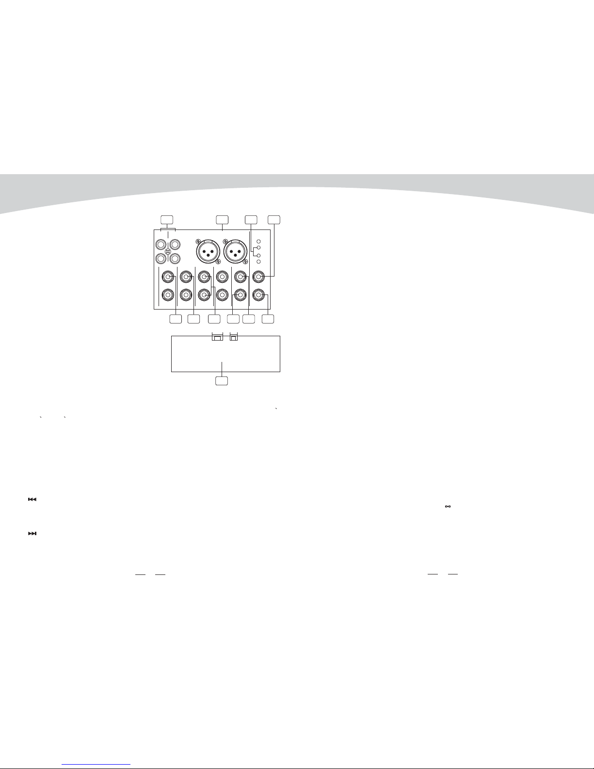
Use the Tape input if you wish to listen to your Mix from a Taper Recorder or DAT. You can
assign the signal coming from the Tape Recorder either to a pair of studio monitor using the
control room assignment on the front panel or you can also send the signal directly to the
Main Mix.
These RCA jacks will route the main mix into a tape recorder.
The stereo output is supplied both XLR and 1/4" TRS sockets, which are used to send the
audio to an amplifier. Through the main mix level control, you can adjust the output level from
- to +10dB.
Use these stereo 1/4" sockets to return the sound of an effect unit to the main mix. You can
also use them as extra auxiliary inputs, but they are primarily used to connect the output of
external effect processors.
These 1/4" phone sockets will be used to send the signal to studio monitor speakers or to a
second set of PA.
This socket is used to connect external foot switch for your convenient operation, it has the
same function as DFX MUTE button.
These 1/4" phone sockets are used to send out the signal from the AUX bus to external devices
such as effects.
32. DIGITAL EFFECTS
33. PHANTOM LED
34. PWR LED
35. 2TK IN / OUT
TAPE IN
TAPE OUT
36. MAIN MIX OUTPUT
37. ST RETURNS
38. CTRL-ROOM
39. FOOT SWITCH
40. AUX SENDS
12 CHANNEL POWERED MIXER
Table of contents
Other SEIKAKU Music Mixer manuals


