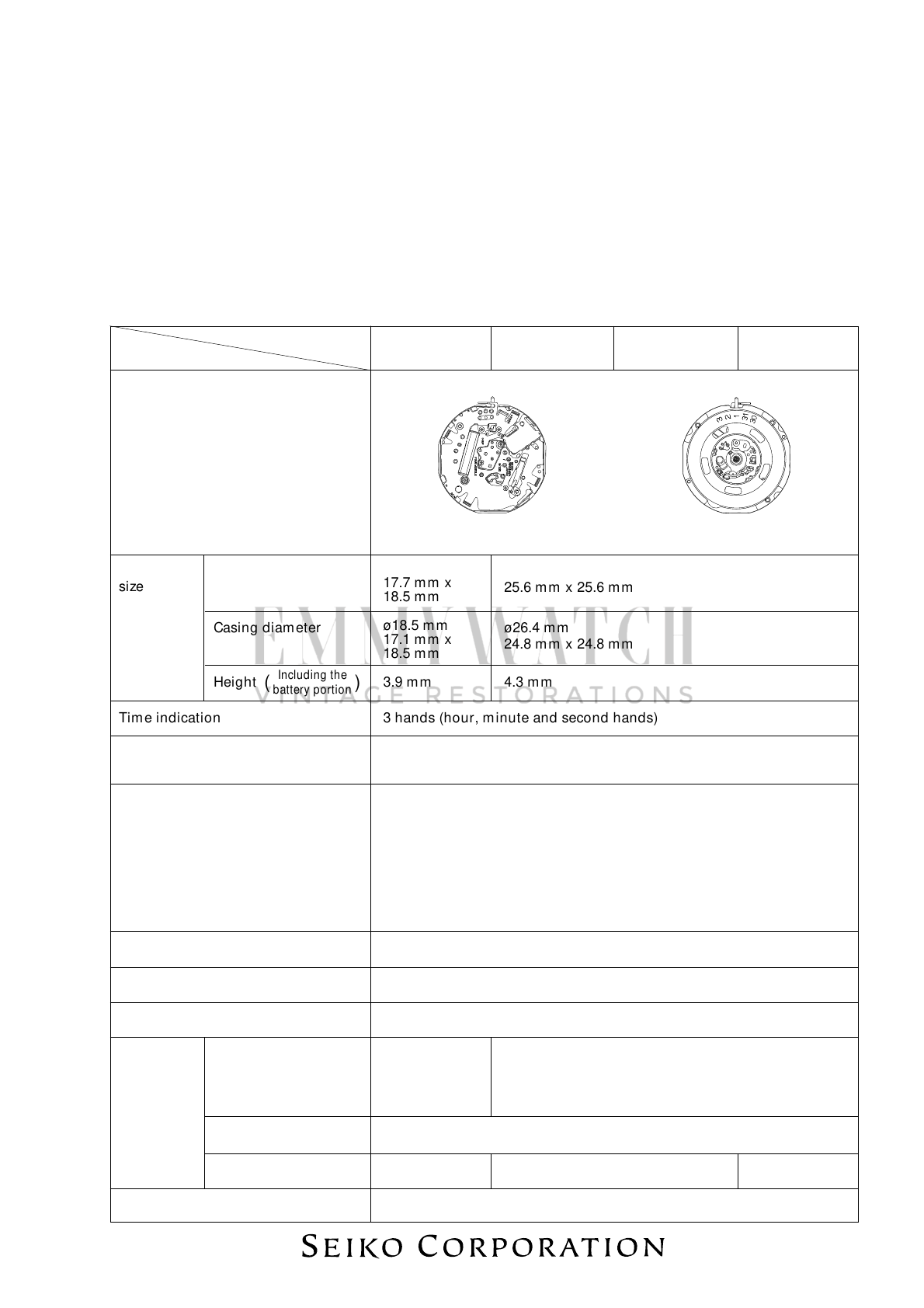
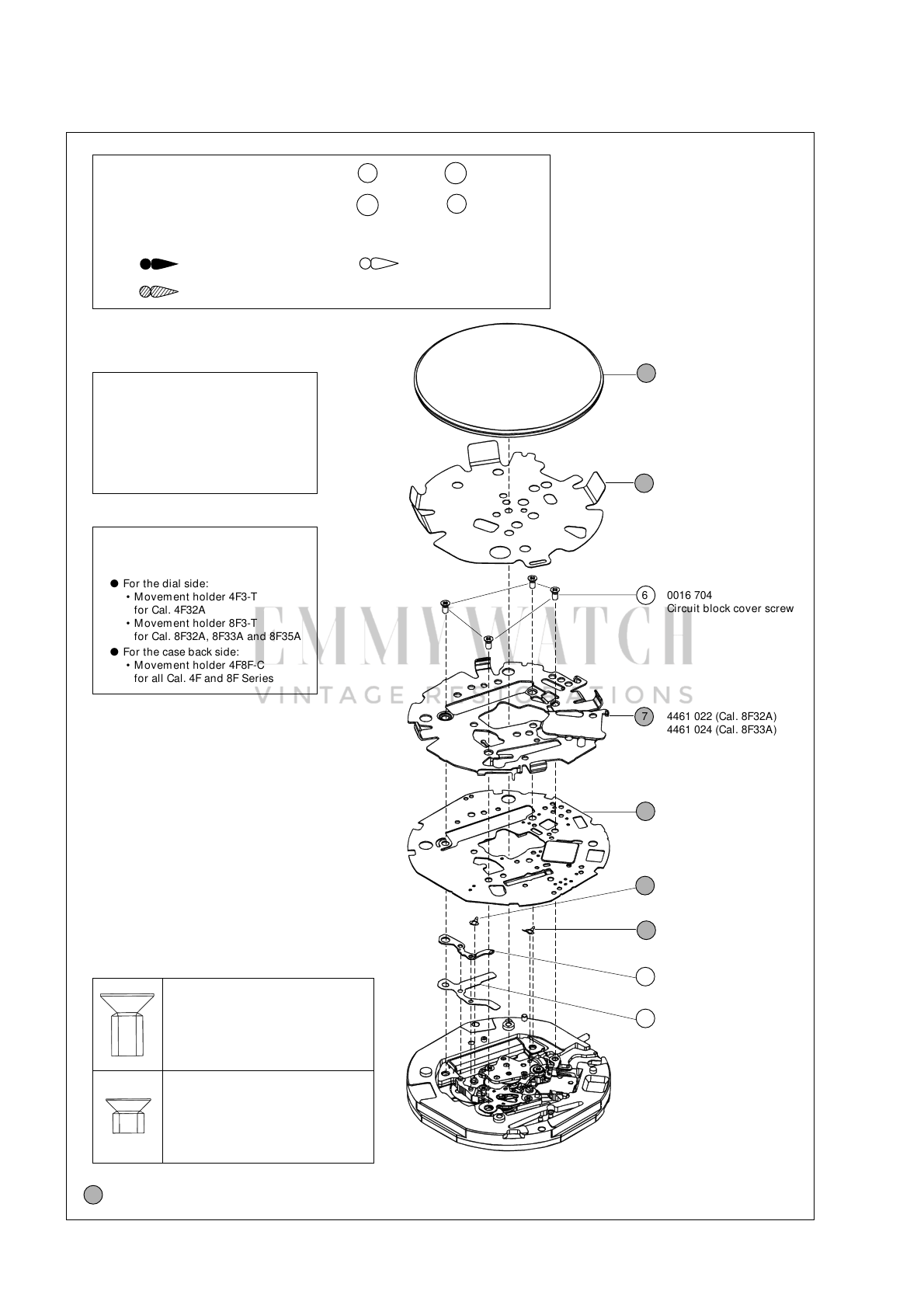
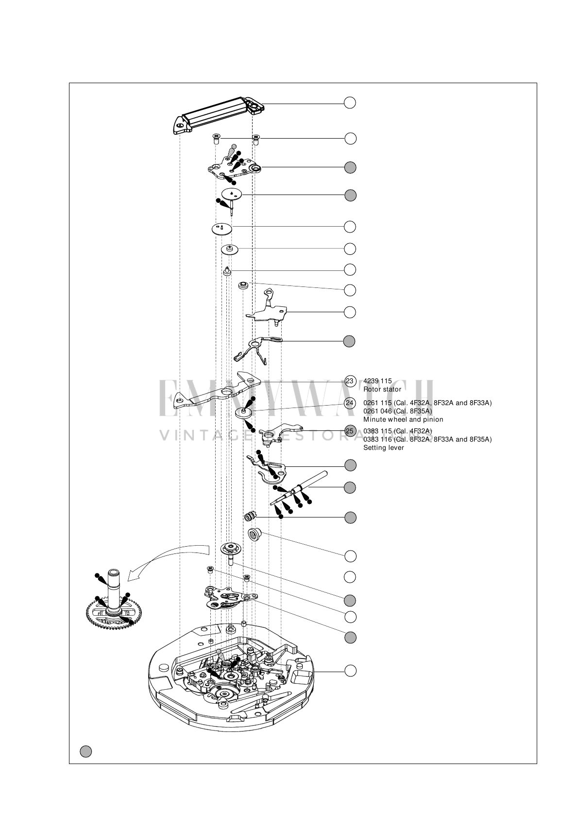
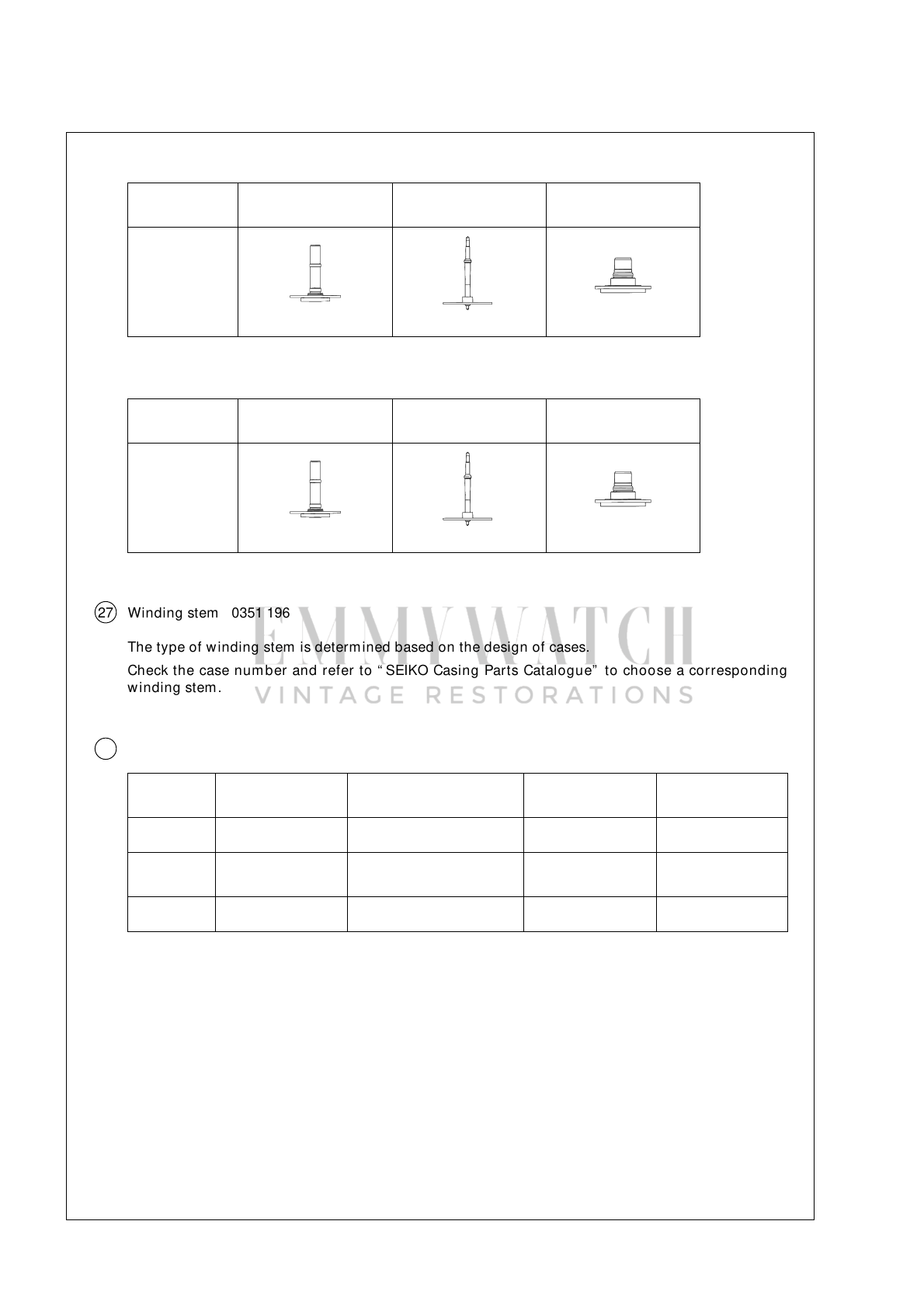
Seiko 4F32A User manual

EMMY
WATCH
VINTAGE
RESTORATIONS
Seiko
4F32A,8F32A,8F33A,8F35A
Movement
Parts
(1)
Compiled
by
EmmyWatch
-
https.//www.emmywatch.com

SEIKO
CORPORATION
1
PARTS CATALOGUE/TECHNICALGUIDE
[SPECIFICATIONS]
Cal. No.
Item 4F32A 8F35A
Movement
8F32A 8F33A
(x 1.0)The illustrations refer to Cal. 8F32A.
Movem ent
size
ø18.5 mm
17.7 mm x
18.5 mm
ø26.4 mm
25.6 mm x 25.6 mm
ø18.5 mm
17.1 mm x
18.5 mm
ø26.4 mm
24.8 mm x 24.8 mm
Tim e indication 3 hands (hour, m inute and second hands)
Outside diam eter
Casing diam eter
Height )
Including the
battery portion
(3.9 mm 4.3 mm
Driving system
Additional mechanism
Loss/gain Annual rate at norm al tem perature range: less than 20 seconds
Regulation system Logical regulation (Pattern cutting system: 3 steps)
Measuring gate by quartz tester Use 10-second gate.
SEIKO CR1612,
Sony CR1612,
Matsushita
CR1612
Battery Battery No. SEIKO CR2412, M atsushita CR2412
Voltage 3.0 V
Battery life Approx. 5 years Approx. 8 yearsApprox. 10 years
Jew els 4 jew els
Cal. 4F32A, 8F32A
Cal. 8F33A, 8F35A
PARTS CATALOGUE/ TECHNICAL GUIDE (p. 1 –22)
CATÁLOGO DE PARTES/ GUÍA TÉCNICA (p. 23 –44)
• Step m otor (for hour, m inute and second hands)
• Ultrasonic motor (for calendar indication)
• Calendar (Leap year indication, m onth and date)
Perpetual calendar up to February 28, 2100
• Train wheel setting device
• Electronic circuit reset switch
• Battery life indicator
• Day calendar (Cal. 8F33A)
• Instant calendar (day) setting device (Cal. 8F33A)

2
PARTS CATALOGUE
Disassem bling procedures Figs. : 1 →43
Reassembling procedures Figs. : 43 ←1
Lubricating: Types of oil Oil quantity
Moebius A Normal quantity
Moebius F
➡➡Please see the rem arks on the follow ing pages.
Cal. 4F32A, 8F32A, 8F33A, 8F35A
Ex. : Cal. 8F32A
Note for Cal. 8F32A and 8F35A:
When the hands and the dial
are rem oved, the dial spacer
will com e off if the m ovement
is turned over. Take care not
to lose the dial spacer.
* Fo r disassem bli ng an d reassem b lin g,
use the movement holder for exclusive
use w ith the respective calibres.
●For the dial side:
• Movement holder 4F3-T
for Cal. 4F32A
• Movement holder 8F3-T
for Cal. 8F32A, 8F33A and 8F35A
●For the case back side:
• Movement holder 4F8F-C
for all Cal. 4F and 8F Series
0016 704
• Circuit block cover screw (4 pcs.)
• Train w heel bridge screw (2 pcs.)
0016 705
• Ultrasonic m otor screw (2 pcs.)
2 Battery
(See the front page)
5 4216 115 (Cal. 4F32A)
4216 117 (Cal. 8F32A,
8F33A and 8F35A)
Insulator for battery (A)
6 0016 704
Circuit block cover screw
7 4461 022 (Cal. 8F32A)
4461 024 (Cal. 8F33A)
4461 033 (Cal. 8F35A)
Circuit block cover
(For Cal. 4F32A, see page 5)
8 4403 218 (Cal. 4F32A)
4403 219 (Cal. 8F32A,
8F33A and 8F35A)
Circuit block
10 4281 118
24-hour contact point
spring
11 4270 415
Battery connection (–)
12 4216 116
Insulator for battery (B)
9 4281 115
Date driving contact
point spring

3
PARTS CATALOGUE
➡➡Please see the rem arks on the follow ing pages.
Cal. 4F32A, 8F32A, 8F33A, 8F35A
Ex. : Cal. 8F32A
23 4239 115
Rotor stator
24 0261 115 (Cal. 4F32A, 8F32A and 8F33A)
0261 046 (Cal. 8F35A)
Minute w heel and pinion
25 0383 115 (Cal. 4F32A)
0383 116 (Cal. 8F32A, 8F33A and 8F35A)
Setting lever
26 0384 115
Yoke
27 Winding stem
28 0282 032 (Cal. 4F32A and 8F32A)
0282 117 (Cal. 8F33A)
0282 116 (Cal. 8F35A)
Clutch w heel
29 4408 115 (Cal. 4F32A, 8F32A and 8F35A)
Clutch w heel spacer
29 0962 119 (Cal. 8F33A)
First intermediate wheel for calendar corrector
30 Center wheel and pinion
41 0016 705
Ultrasonic stator unit screw
42 4234 115
Ultrasonic stator unit
43 0100 136 (Cal. 4F32A)
0100 137 (Cal. 8F32A, 8F33A and 8F35A)
Main plate
13 4002 115
Coil block
14 0016 704
Train w heel bridge screw
15 0125 254
Train w heel bridge
16 Fourth w heel and pinion
17 0231 116
Third w heel and pinion
18 0701 115
Fifth w heel and pinion
19 4146 116
Step rotor
20 0281 115
Setting wheel
21 0388 117 (Cal. 4F32A)
0388 116 (Cal. 8F32A, 8F33A and 8F35A)
Yoke guard
22 0391 115
Train w heel setting lever

4
PARTS CATALOGUE
➡➡Please see the rem arks on the follow ing pages.
Cal. 4F32A, 8F32A, 8F33A, 8F35A
Cal. 4F32A, 8F32A & 8F35A
Ex. : Cal. 8F32A
Cal. 8F33A
* Cal. 4F32A, 8F32A and 8F35A do not use the parts 3 , 4 , 31 and 37 .
1 4408 116
(Cal. 8F32A and 8F35A)
Dial spacer
32 0808 126
Date dial guard
33 Date dial
34 0810 115
Date jum per
35 Hour w heel
36 0817 118
Interm ediate date driving
wheel and pinion
38 4062 117
Ultrasonic rotor
39 1019 114
24-hour w heel
40 0802 115
Date driving w heel
3 0963 230
Snap for day star
with dial disk
4 Day star with
dial disk
32 0808 125
Date dial guard
33 Date dial
31 0989 007
Day corrector
wheel
38 4062 117
Ultrasonic rotor
39 1019 115
24-hour w heel
40 0802 115
Date driving
wheel
36 0817 118
Interm ediate date
driving w heel and
pinion
37 0962 118
Second interm ediate
wheel for calendar
corrector
35 Hour w heel
34 0810 115
Date jum per

1919108
I
a
5
PARTS CATALOGUE Cal. 4F32A, 8F32A, 8F33A, 8F35A
Remarks:
●Back plate
Som e models do not use the back plate.
●Case ring
The type of case ring is determined based on the design of cases.
Check the case number and refer to “ SEIKO Casing Parts Catalogue” to choose a corresponding case ring.
4 Day star w ith dial disk (Only for Cal. 8F33A)
Position of crow n
and calendar frame
Cal. No. Color of figurePart code Color of
background
8F33A 0170 072 3 o’clock Black White
The type of day star w ith dial disk is determined based on the design of cases.
Check the part code printed on the disk.
7 Circuit block cover
16 Fourth w heel and pinion
30 Center wheel and pinion
35 Hour w heel
•Discrimination of the hand installation height
Cal. 4F and 8F Series w atches have num erals printed on
movem ent to indicate the hand installation height. When
repairing, refer to the table below .
Circuit
block cover
Num eral for
discrim ination
Center w heel
and pinion
Fourth w heel
and pinion Hour wheel
1
4461 021 0221 116 0241 449 0273 118
2
4461 020 0221 114 0241 448 0273 117
[ Cal. 4F32A ]
Numeral for discrimination

6
PARTS CATALOGUE Cal. 4F32A, 8F32A, 8F33A, 8F35A
[ Cal. 8F32A and 8F33A ]
Num eral for
discrim ination
2
Center w heel
and pinion
Fourth w heel
and pinion Hour wheel
0221 115 0241 446 0273 115
[ Cal. 8F35A ]
Num eral for
discrim ination
2
Center w heel
and pinion
Fourth w heel
and pinion Hour wheel
0221 123 0241 446 0273 115
27 Winding stem 0351 196
The type of w inding stem is determ ined based on the design of cases.
Check the case num ber and refer to “ SEIKO Casing Parts Catalogue” to choose a corresponding
winding stem.
33 Date dial
Position of crow n
and calendar frame
Cal. No. Color of figurePart code Color of
background
4F32A 0878 321 3 o’clock Black White
8F35A 0878 301 4 o’clock White Black
8F32A
8F33A 0878 301 3 o’clock White Black
The type of date dial is determ ined based on the design of cases.
Check the case num ber and refer to “ SEIKO Casing Parts Catalogue” to choose a corresponding date
dial.

7
TECHNICAL GUIDE
•The explanation here is only for the particular points of Cal. 4F32A, 8F32A, 8F33A and 8F35A.
•For the repairing, checking and m easuring procedures, refer to the “ TECHNICAL GUIDE, GENERAL
INSTRUCTIONS” .
I. STRUCTURE OF THE CIRCUIT BLOCK
Cal. 4F32A, 8F32A, 8F33A, 8F35A
[ Cal. 4F32A ]
[ Cal. 8F32A, 8F33A and 8F35A ]
“ ø” terminal
(for resetting the date dial)
“ M” terminal
(for month setting)
“ Y” terminal
(for year setting)
“ D” terminal
(for date setting)
AC terminal
Coil block output terminal
Input terminal (+)
C-MOS-IC
Input terminal (–)Crystal unit
“ ø” terminal
(for resetting
the date dial)
“ M ” terminal (for month setting)
“ D” terminal
(for date setting)
AC terminal
“ Y” terminal
(for year setting)
Coil block output terminal
Input terminal (+)
C-MOS-IC
Input terminal (–)Crystal unit

8
TECHNICAL GUIDE
II. REM ARKS ON DISASSEM BLING AND REASSEM BLING
Cal. 4F32A, 8F32A, 8F33A, 8F35A
●Hour, minute and second hands
•For disassembling and reassembling, use the movement holder for exclusive use with the respective
calibres.
•When installing the hands, place the m ovem ent directly on a flat m etal plate or a riveting plate.
•How to set the hands
With the battery installed, place the movement directly
on a flat m etal plate or a riveting plate, taking care not
to press down the hooking portions.
To install the hands:
Turn the crown clockwise until the date changes, and install the hands so that they point to the 12 o’clock
position.
To install the hands so that the date changes more accurately as the hands indicate 12 o’clock midnight:
1) Turn the crow n clockwise until the date changes.
2) Give the crown four counterclockw ise turns to m ake the date return to the previous date.
3) Turn the crow n slowly clockwise until the date changes again.
4) Install the hands so that they point to the 12 o’clock position.
•Setting position of the movement on the exclusive movement holder
Check that the pins of the m ovem ent holder are securely set to the corresponding holes of the
movem ent.
[ Movement holder 4F3-T for the dial side of Cal. 4F32A movement ]
[ Movement holder 8F3-T for the dial side of Cal. 8F32A, 8F33A and 8F35A movements ]
Hooking portion
Battery
Pin Hole to set the pin

OO
A!
A
9
TECHNICAL GUIDE Cal. 4F32A, 8F32A, 8F33A, 8F35A
[ Movement holder 4F8F-C for the case back side of all Cal. 4F and 8F Series movements ]
2 Battery
5 Insulator for battery (A)
•Be sure to complete the battery replacement w ork w ithin three minutes. Otherw ise, the
calendar data stored in the built-in IC will be erased.
•Before rem oving the old battery, be sure to keep a new battery at hand.
•When installing the new battery, take utm ost care not to short-circuit the battery connection
(–) and the circuit block cover, as this w ill also erase the calendar data.
•How to replace the battery
•How to remove the battery
The case ring has numerals printed on it to show the order of disengaging the hooking portions of
the circuit block cover using the tips of the tweezers.
[ Case ring for Cal. 4F32A ] [ Case ring for Cal. 8F32A, 8F33A and 8F35A ]
12 o’clock
side
Crow n side
12 o’clock side
Crow n side
Pin
Hole to set the pin

10
TECHNICAL GUIDE Cal. 4F32A, 8F32A, 8F33A, 8F35A
[ Cal. 4F32A ]
1. Locate the position where num eral “ 1” is printed on the case ring, and insert the tips of the
tw eezers into the gap betw een the insulator for battery (A) and the circuit block cover, w hile
taking care not to damage the coil.
* Take care not to insert the tips of tw eezers too deep into the gap as this m ay damage the coil.
Numeral “ 2” Insulator for battery (A)
Tw eezers
Circuit block cover
Numeral “ 1”
Insulator for battery (A)
Circuit block cover
2. Pry w ith the tweezers to disengage the hooking portion of the circuit block cover.
3. Locate the position where numeral “ 2” is printed on the case ring, and use the tips of the tw eezers
in the same m anner as in the steps “ 1” and “ 2” above and disengage the hooking portion of the
circuit block cover to remove the battery.
Insulator for battery (A)
Hooking portion of
the circuit block cover
Circuit block cover
Tw eezers
Hooking portion of
the circuit block cover
Circuit block cover
Insulator for battery (A)
Tw eezers
Tw eezers

11
TECHNICAL GUIDE Cal. 4F32A, 8F32A, 8F33A, 8F35A
[ Cal. 8F32A, 8F33A and 8F35A ]
1. Locate the position where num eral “ 1” is printed on the case ring, and insert the tips of the
tweezers into the gap betw een the insulator for battery (A) and the circuit block cover . Then, pry
with tw eezers in the direction of the arrow in the illustration below to disengage the hooking
portion of the circuit block cover. While doing so, take care not to damage the coil.
* Take care not to insert the tips of tw eezers too deep into the gap as this m ay damage the coil.
Insulator for battery (A)
2. Locate the position where num eral “ 2” is printed on the case ring, and insert the tips of the
tweezers into the gap betw een the insulator for battery (A) and the circuit block cover . Then, pry
with tweezers in the direction of the arrow in the illustration below to rem ove the battery.
Tw eezers
Circuit block cover
Tw eezers
Circuit block cover
Hooking portion of
the circuit block cover
Insulator for battery (A)
Hooking portion of
the circuit block cover
Circuit block cover Tw eezers
Tw eezers
Insulator for battery (A)
Hooking portion
of the circuit
block cover
Circuit block cover

SEIKO
TIME
CORP.
JAPAN
)10
©
>
12
TECHNICAL GUIDE Cal. 4F32A, 8F32A, 8F33A, 8F35A
•How to install the battery (For Cal.4F32A, 8F32A, 8F33A and 8F35A)
[A] When the dial and hands are installed, set the time to 6:00 AM or PM .
[B] When the dial and hands are not installed, direct the notched portion of the 24-hour hand tow ard
the 9 o’clock side.
Note: When installing the battery, take care lest the battery connection (–) should touch the four
hooking portions of the circuit block cover, the grounding portion and the portion for battery
check.
1. Before installing the battery, straighten the three hooking portions of the insulator for battery (A).
Notched portion of 24-hour hand
9 o’clock side
Grounding portion
Hooking portion
Insulator for battery (A)
Portion for battery check
2. First, set a part of the battery into the portion for battery check in the direction indicated by the arrow
1 , and then, press it dow n to install it com pletely.
Hooking portion
Portion for battery check
Grounding portion
Note: Set the insulator for battery (A) securely in position, as it easily gets out of position.
1

13
TECHNICAL GUIDE Cal. 4F32A, 8F32A, 8F33A, 8F35A
•Necessary procedure after battery change
1. After the battery is replaced with a new one, be sure to contact the “ AC” terminal of the circuit block
and the (+) surface of the battery with conductive tweezers for more than three seconds, with the
crow n at the norm al position.
2. Pull out the crown all the w ay to the second click, and then, push it back in to the normal position.
Repeat this procedure tw ice.
•If the date dial w ill not turn, and the second
hand starts moving at 5-second intervals, the
calendar data has been erased.
•If the date dial returns to the current date, and
the second hand starts moving at one-second
intervals, the calendar data is securely retained.
➪
➪
Input the calendar data following the procedure
in “ Inputting the calendar data” .
Th e b att ery r epl acem ent w o r k has b een
com pleted successfully. Next, set the time.
•Inputting the calendar data
•Input each type of calendar data in the follow ing order:
ø
Resetting
the date dial position
Set the date dial to “ 1” .
Y
Year setting
Set the date dial to
the current year.
M
Month setting
Set the date dial to
the current m onth.
D
Date setting
Set the date dial to
the current date.
* Be sure to reset the date dial position first.
▲
▲
▲
•Positions of each term inal of the circuit block
[ Cal. 4F32A ] [ Cal. 8F32A, 8F33A and 8F35A ]
Tw eezers
“ AC”
“ D” (Date)
“ Y “ (Year)
“ M” (Month) “ ø”
“ Y “ (Year)
“ M” (Month)
“ ø”
Tw eezers
“ AC”
“ D” (Date)
■Basic routine of inputting each type of calendar data
1) Contact the (+) surface of the battery and the terminal of the circuit block (“ ø” , “ Y” , “ M” or “ D” ) with
conductive tw eezers once to activate the mode of inputting the desired type of data to the watch.
2) Contact the (+) surface of the battery and the terminal of the circuit block with tw eezers repeatedly
to turn the date dial until the desired num eral appears in the calendar frame. Each contact w ith the
tw eezers advances the date dial by one. It advances one by one and will not be advanced quickly.

14
TECHNICAL GUIDE Cal. 4F32A, 8F32A, 8F33A, 8F35A
■Procedure of inputting the calendar data
1. Pull out the crow n all the way to the second click.
2. Reset the position of the date dial. (ø)
First, contact the “ ø” terminal and the (+) surface of the battery with conductive tw eezers to activate the
date dial resetting mode, and then, contact the tw o portions repeatedly with tweezers until “ 1” appears
in the calendar frame.
3. Set the year. (Y)
Contact the “ Y” term inal and the (+) surface of the battery w ith conductive tweezers to activate the year
setting m ode. “ 1” appears in the calendar fr am e. Then, contact the tw o portions repeatedly w ith
tw eezers until the current year appears in the calendar fram e.
Notes:
* The date dial turns back w hen the num eral returns from “ 4” to “ 1” in the calendar fram e.
* If any data has already been input before the year setting m ode is activated, a numeral other than “ 1”
may appear in the calendar fram e.
Numeral in the
calendar frame: 1 2 3 4
One year since
the last leap year
Tw o years since
the last leap year
Three years since
the last leap year
Leap year
▲
▲
▲
▲
Numeral in the calendar frame
1 2 3 4
One year since
the last leap year
Two years since
the last leap year
Three years since
the last leap year Leap year
1997
2001
2005
2009
•
•
2085
2089
2093
2097
1998
2002
2006
2010
•
•
2086
2090
2094
2098
1999
2003
2007
2011
•
•
2087
2091
2095
2099
2000
2004
2008
2012
•
•
2088
2092
2096
Year
4. Set the m onth. (M)
Contact the “ M” terminal and the (+) surface of the battery w ith conductive tw eezers to activate the month
setting m ode. “ 1” appears in the calendar fr am e. Then, contact the tw o portions repeatedly w ith
tw eezers until the current m onth appears in the calendar fram e.
Notes:
* The date dial turns back w hen the num eral returns from “ 12” to “ 1” in the calendar fram e.
* If any data has already been input before the m onth setting mode is activated, a num eral other than
“ 1” may appear in the calendar frame.
Numeral in the
calendar frame: 1 2 3 4 5 6 7 8 9 10 11 12
▲
▲
▲
▲
▲
▲
▲
▲
▲
▲
▲
▲

Y
15
TECHNICAL GUIDE Cal. 4F32A, 8F32A, 8F33A, 8F35A
5. Set the date. (D)
Contact the “ D” terminal and the (+) surface of the battery with conductive tweezers to activate the date
setting m ode. “ 1” appears in the calendar fram e. Then, contact the two portions repeatedly w ith
tw eezers until the current date appears in the calendar fram e.
Notes:
* The date dial only advances and w ill not turn back in the date setting m ode.
* If any data has already been input before the date setting m ode is activated, a numeral other than “ 1”
may appear in the calendar fram e.
●How to check the calendar
Pull out the crown to the first click, and push it back in to the norm al position w ithin a second.
* Take care not to pull out the crown all the w ay to the second click. The calendar cannot be checked.
The calendar w ill be shown in the fram e in the follow ing order.
(1) Year (2) Month (3) Date
▲
▲
(1) The second hand m oves at 5-second intervals and stops. The num ber of seconds it has advanced
indicates the number of years that have passed since the last leap year. Five seconds correspond
to one year.
* Before pulling out the crown to the first click, check and remember w here the second hand is so
that you can read how many seconds it has advanced.
* If the second hand has advanced 20 seconds (four tim es of five seconds), the current year is the
leap year.
Quick movement of
the second hand
Number of years since
the last leap years
5 seconds 10 seconds 15 seconds 20 seconds
1 year 2 years 3 years 4 years (leap year)
(2) After the second hand indicates the number of years since the last leap year, the numeral in the
calendar frame changes to indicate the current m onth for five seconds.
(3) After the current m onth is show n, the current date is indicated in the calendar fram e.
* When the month and date are represented by the same numeral as in the case of “ January 1st” ,
“ February 2nd” and so on, the numeral in the calendar frame quickly advances and moves back
by one to indicate that the m onth and date num erals are identical.
(4) After the current date is shown, the second hand quickly moves to catch up with the current second
and starts moving at normal one-second intervals thereafter.
(5) If the calendar is correctly set as you intended, set the desired tim e.
6. Check if the day dial is reset to “ 1” .
Contact the “ ø” terminal and the (+) surface of the battery with conductive tweezers once to check that
“ 1” appears in the calendar frame. If not, repeat the procedure again starting from step “ 2” above.
7. Push back the crow n in to the norm al position, and check if the number of years since the last leap years,
month and date are correctly set. (See “ How to check the calendar” below)

Be
16
TECHNICAL GUIDE Cal. 4F32A, 8F32A, 8F33A, 8F35A
*If the year, month or date is not correctly set, repeat the procedure of inputting the calendar data
starting from step “1”.
7 Circuit block cover
When setting the circuit block cover, take care not to press down the term inal for battery check and the
grounding term inal.
[ Cal. 4F32A ] [ Cal. 8F32A, 8F33A and 8F35A ]
Terminal for battery check Terminal for battery check
8 Circuit block
Before replacing the circuit block, make sure that the crow n is pulled out to the first click.
Also, check that the tip of the reset lever is positioned at the center of the eyehole as show n in the
illustration below , and then, reassemble the circuit block.
Note: When setting the circuit block, take care not to press down on the reset lever.
Grounding terminal
Reset lever terminal
9 Date driving contact point spring
10 24-hour contact point spring
•Setting position
24-hour contact
point spring
4281 118
Date driving contact
point spring
4281 115
Note: The date driving contact spring and the 24-hour contact point spring contact with the circuit block
to drive and control the ultrasonic m otor. Handle them with care so as not to bend or straighten
these parts, as this will cause defective contact w ith the circuit block, resulting in a malfunction
of the ultrasonic m otor and defective calendar indication.

17
TECHNICAL GUIDE Cal. 4F32A, 8F32A, 8F33A, 8F35A
15 Train w heel bridge
•Setting position of wheels Step rotor
Fifth wheel and pinion
Setting wheel
Minute w heel and pinion
Fourth w heel and pinion
Third w heel and pinion
22 Train w heel setting lever
25 Setting lever
26 Yoke
•Setting position
Train wheel setting lever
Setting lever
Yoke
Note: Take care not to deform the spring portion of the yoke. While the circuit block cover is removed,
do not pull out or push in the crown.
28 Clutch w heel
Install the clutch wheel in such a manner that the gear having smaller
teeth faces tow ard the center of the center w heel and pinion.
Clutch w heel
31 Day corrector w heel (For Cal. 8F33A)
•How to remove
To remove the day corrector wheel from the second intermediate wheel for calendar corrector, insert
a tip of tw eezers into the hole of day corrector wheel as shown in the illustration, and move it tow ard
the center tube of the m ovement (in the direction of the arrow in the illustration).
Day corrector w heel
Tip of tw eezers
Day corrector
wheel
Clutch w heel
spacer

18
TECHNICAL GUIDE Cal. 4F32A, 8F32A, 8F33A, 8F35A
32 Date dial guard
•How to remove
1. Lightly lift the A portion of the date dial guard
with tweezers to clear it from the guide pin, and
then, m ove it in the clockw ise direction until it
gets on the guide pin.
2. Release the B portion of the date dial guard in the
same m anner as you release the A portion, and
then, m ove it in the clockw ise direction until it
gets on the guide pin.
3. Check that all the three protrusions of the date
dial guard have come off from the main plate, and
then, rem ove the date dial guard.
A portion
Protrusion D
Protrusion C
B portion
Protrusion E
Tw eezers
Guide pin
Protrusion
Date dial guard
A portion
Note: Take care not to deform the date dial guard, as
it is softly built.
•How to remove the date dial guard in replacing the date dial
(with the parts on the movement side installed)
Be sure to use the m ovem ent holder 4F8F-C for
exclusive use for replacing the date dial.
Unlike conventional movements, the date dial guard is not fixed with screws. It is set to the m ain plate
with the three protrusions, which are caught under the main plate by turning the guard. Then, it is fixed
by the tw o guide pins. B portion
•How to install
1. Put the date dial guard on the m ain plate so that
the A and B portions are over the guide pins, as
shown in the illustrations at right.
2. M ove protrusion D of the date dial guard in the
counterclockw ise direction so that it is caught
under the main plate.
3. Sl i ght ly m ov e pro t ru si ons C an d E in t h e
counterclockwise direction alternately to set them
under the main plate. While doing so, set the A
and B portions of the date dial guard to the guide
pins.
Note: Take care not to press dow n the ultrasonic
rotor pinion w hile installing the date dial guard.
Ultrasonic
rotor pinion
Note: Never rem ove the date driving wheel and the
24-hour w heel. Otherwise, the date driving
contact point spring and the 24-hour contact
point spring will com e off.
24-hour w heel
Date driving
wheel

19
TECHNICAL GUIDE Cal. 4F32A, 8F32A, 8F33A, 8F35A
36 Interm ediate date driving wheel and pinion
38 Ultrasonic rotor
39 24-hour w heel
40 Date driving wheel
•Setting position
(For Cal. 4F32A, 8F32A and 8F35A)
Refer to the illustration at right.
Note: Take care not to damage or deform the pinions of the ultrasonic rotor and date driving wheel in
reassem bling and disassembling, as they are m ade of plastic.
38 Ultrasonic rotor
42 Ultrasonic stator unit
Note: When holding the ultrasonic rotor and ultrasonic stator unit with tw eezers, be sure to catch the
portions illustrated below. Otherw ise, their functions will be adversely affected.
24-hour w heel
Ultrasonic rotor
Intermediate date driving
wheel and pinion
Date driving w heel
Tw eezers Tweezers
Tw eezers
Ultrasonic stator unitUltrasonic rotor
•Setting position
(For Cal. 8F33A)
36 Interm ediate date driving wheel and pinion
37 Second interm ediate wheel for calendar corrector
38 Ultrasonic rotor
39 24-hour w heel
40 Date driving wheel
Refer to the illustration at right.
Note: Take care not to damage or deform the pinions of the ultrasonic rotor and date driving wheel in
reassem bling and disassembling, as they are m ade of plastic.
Second intermediate
wheel for calendar
corrector
24-hour w heel
Ultrasonic rotor
Intermediate date driving
wheel and pinion
Date driving w heel
Other manuals for 4F32A
1
This manual suits for next models
3
Table of contents
Other Seiko Watch manuals

Seiko
Seiko 5Y75 User manual

Seiko
Seiko 4R36 User manual

Seiko
Seiko STOPWATCH S143 User manual

Seiko
Seiko Presage SSA439J User manual

Seiko
Seiko ALBA W071 User manual

Seiko
Seiko S822 User manual

Seiko
Seiko 8R46 User manual

Seiko
Seiko 4R35 User manual

Seiko
Seiko Essentials SSB333 User manual

Seiko
Seiko 8M26A Installer manual

Seiko
Seiko CAL. V176 User manual

Seiko
Seiko V195A Quick start guide

Seiko
Seiko Presage SPB401 User manual

Seiko
Seiko C-26 User manual

Seiko
Seiko Cal. V175 User manual

Seiko
Seiko KINETIC 7D56 User manual

Seiko
Seiko 0634A Quick start guide

Seiko
Seiko ASTRON Installation guide

Seiko
Seiko 4S77A Installer manual

Seiko
Seiko Y911A Quick start guide