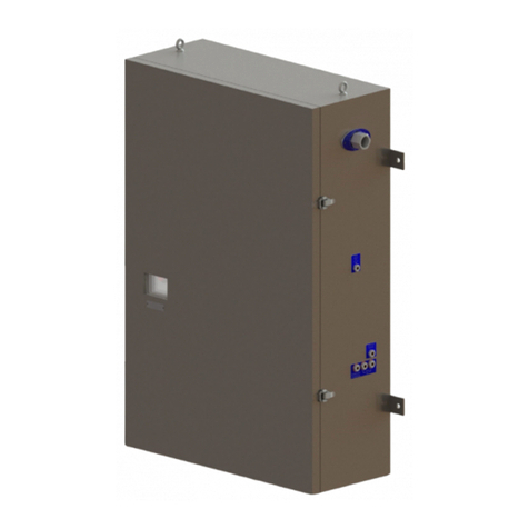
seikoh giken SEI-SFP550 Series User manual

SFP-550E3 Operating Manual
FP-IM55E3 (Ver. 2.0)
SFP-
550E3
Operating Manual

SFP-550E3 Operating Manual
FP-IM55E3 (Ver. 2.0)
1/26
Safety Precautions
This manual shows the following symbols for proper and safety operation of SFP-550E3
polishing machine and for prevention of damages to the polishing machine.
Below explains meanings of each symbol. Please read and have your understanding
and follow the instructions indicated by the markings.
Examples of Symbols
This symbol refers to any caution (including danger and
warning). Example in the left shows “Warning or
Precaution” for safety.
This symbol refers to any prohibition.
Example in the left shows “No disassembly.”
T This symbol refers “Unplug the power cable from the
outlet.”
Caution
Warning Improper handling with negligence of this
precaution may result in death or serious injury
Improper handling with negligence of this
precaution may result in injury or material

SFP-550E3 Operating Manual
FP-IM55E3 (Ver. 2.0)
2/26
Never touch or gain access to moving parts, the arm of the fiber
holder hand or finger during operation. Otherwise, you may injure.
Do not touch the polishing machine during operation.
Do not replace polishing holder during operation.
Please unplug power cable after work.
Do not touch the operation panel or the switch with wet hand or
Do not connect or disconnect the power cable with wet hand.
Otherwise, you may get electric shock, accident or failure may
occur.
Be sure to use specified voltage and connect grounding terminal
(Class 3 or greater grounding). Otherwise, fire, electric shock,
accident or failure may occur
Turn off the power and unplug the cable from the outlet for the
following cases. Otherwise, fire, electric shock, or accident
may occur.
When fuse is replaced (use 2A)
When any abnormalities such as abnormal odor, smoke or
abnormal noise are occurred.
Warning

SFP-550E3 Operating Manual
FP-IM55E3 (Ver. 2.0)
3/26
Never perform the following actions. Otherwise, fire,
electric shock, accident or failure may occur.
Please wear proper uniform and safety shoes when you
work
Please place the polishing machine on flat and rigid work
table.
Do not place any object on the polishing machine
Do not place or leave the polishing machine outdoor or at
the place where the polishing machine is exposed to
water.
Be careful not to fall the polishing machine in transport
condition.
Do not apply shock or drop the polishing machine.
Do not place any objects on the power cable.
Do not twist or pull the cable strongly.
Do not operate the polishing machine in unmanned.
Turn off the switch when leaving from the polishing
machine.
Keep away any flammable substances or explosives from
the polishing machine.
Do not place any objects within 30cm from the cooling fan.
Do not put anything inside the polishing machine. This
may cause accident or failure.
To prevent corrosion, remove any liquid completely from
the polishing machine and avoid using and keeping the
polishing machine in humid condition.
Do not disassemble the polishing machine more than
described in the manual.
Seikoh Giken does not assume any responsibility for products manufactured with
the polishing machine.
Caution

SFP-550E3 Operating Manual
FP-IM55E3 (Ver. 2.0)
4/26
Introduction
–Thank you for purchasing SFP-550E3 Polishing Machine –
This operating manual covers operating procedures for SFP-550E3 Polishing Machine
in depth. Before use, read this manual carefully and familiarize yourself with the
various features and functions of this machine.
Features of SFP-550E3
Designed to polish the ferrule end faces of fiber-optic connectors with high quality and
productivity, the SFP-550E3 offers the following features:
H
Hi
ig
gh
hP
Pr
ro
od
du
uc
ct
ti
iv
vi
it
ty
ya
an
nd
dL
Lo
ow
wC
Co
os
st
tP
Pe
er
rf
fo
or
rm
ma
an
nc
ce
e
Capability of quick polishing up to 48 ferrules* at once provides high
productivity and low cost performance.
(*The number of ferrules varies slightly depending on the types of
connectors.)
High quality polishing as back reflection of 50dB min (HPC polishing) by
right-angled convex polishing and 60dB min (Angled PC) by angled convex
polishing can be obtained.
Easy Operation
Both operation and maintenance are remarkably easy and require no special
skills.
Wide Range of Application
Applicable to FC, SC, ST, LC, MU, E2000, MT and other various connector
types in high precision polishing of physical contact, angled physical contact
or flat contact, simply by changing the polishing holders.

SFP-550E3 Operating Manual
FP-IM55E3 (Ver. 2.0)
5/26
******* Contents *******
Page
1. Specification
1.1 Structure and Parts
1.2 Standard Specification
1.3 Standard Accessories
2. Operating Procedures
2.1 Operation Panel
2.2 Touch Panel
2.3 Turntable Assembly
2.4 Polishing Materials
2.5 IPC Polishing Holder
2.6 Pressurizing and Holding Unit
2.7 Operation
…………………………………...
…………………………………...
…………………………………...
Front Panel …………………..
Rear Panel …………………...
Program Polishing .………….
Program Setting .…………….
Manual Polishing ……………
Maintenance …………………
Battery Replacement…………..
Turntable Structure ………….
Maintenance for Turntable
Assembly ……………………..
Polishing Films ………………
Polishing Pads ……………….
Polishing Holder Design ……
…………………………………...
…………………………………...
6
8
9
10
11
12
14
17
19
21
23
23
23
24
25
26
26

SFP-550E3 Operating Manual
FP-IM55E3 (Ver. 2.0)
6/26
1. Specification
1.1 Structure and Parts
Polishing Pad and
Polishing Film
Clamping
Post
Turntable
Polishing
Holder

SFP-550E3 Operating Manual
FP-IM55E3 (Ver. 2.0)
7/26
Power Inlet
Fuse Holder
Cooling Fan
Cable Hanger
Power Switch
Emergency
Stop Button
Touch Panel

SFP-550E3 Operating Manual
FP-IM55E3 (Ver. 2.0)
8/26
1.2 Standard Specifications
Item Specification
Power Supply
Voltage, Frequency
Power Consumption
AC100-240V, 50Hz/60Hz
80VA
Drive Unit
Revolution Motor
Revolution Speed
Rotation Motor
Rotation Speed
Cooling Fan
50W motor with reduction gear
70-200 rpm
30W motor with reduction gear
0.7-2.0 rpm
(1/100 of revolution speed
automatically adjusted)
φ80 mm propeller fan
Operating Unit
Touch Panel
Power Switch
Emergency Stop Button
Rocker switch
Pressurizing Unit
Pressurizing Method By clamps on the four corners
with coil
springs.
Polishing Materials
Polishing Film
Polishing Pad
Outer diameter: 127mm, plastic base
Glass pad for flat polishing
Synthetic rubber pad for PC/APC polishing
Performance
PC Polishing
(φ2.5 Pre-Domed Ferrule)
Angled PC Polishing
(φ2.5 Step Ferrule)
4 processes, 2.0min approx. (HPC polishing)
5 processes, 3.0min approx. (APC polishing)
Dimensions and Weight
Dimensions
Weight
W230 x D310 x H295
18.5kg
Note: Above specifications are subjected to change without notice.

SFP-550E3 Operating Manual
FP-IM55E3 (Ver. 2.0)
9/26
1.3 Standard Accessories for Polishing Set
Note: Above accessories are subjected to change without notice.
Parts Name P/N Qty
Other Accessories
Coil spring RP55C-14 4
2A fuse RP55-56 2
Hexagon wrench L RP55C-71 1
Hexagon wrench S RP55C-72 1
M5-45 bolt RP55C-73 1
Power cable RP55-30 1
Cable hanger FP-CH 1
Manual
Operation manual FP-IM55E3 1
Process manual FP-PM55E3 1
Maintenance manual FP-MM55E3 1

SFP-550E3 Operating Manual
FP-IM55E3 (Ver. 2.0)
10/26
2. Operating Procedures
2.1 Operating Panel
◆Front Panel
<Operation Procedure>
①Power Switch ON
Ensure that the emergency stop button is off and then turn on the power switch. After the
power switch is turned on, the cooling fan will start running and the main menu screen appears.
Maintenance screen will appear when the total polishing time has been over the limit for regular
inspection/maintenance. Detail for the maintenance screen is on page 19-20.
②Machine Operation
SFP-550E3 is operated by the screen of the touch panel. Detail for the operation with the
touch panel is in page 12-18.
Emergency
Stop Button
Power
Switch
Touch Panel

SFP-550E3 Operating Manual
FP-IM55E3 (Ver. 2.0)
11/26
③Emergency Stop Button
The machine is stopped when the emergency stop button is pushed (ON) during polishing.
During the emergency stop is on, the following screen is appeared and the machine does not
function. To resume machine in function (emergency stop OFF), press and turn the emergency
stop button slightly in clockwise.
④ Power Switch OFF
When you finish operation, make sure to turn off the power switch. Also ensure to go back to
“Main Menu” screen before turning off the power switch. Do not turn it off during polishing or
the programs may be erased.
◆Rear Panel
<Fuse Holder>
To change fuse, pull out the Fuse Holder and take out the fuse from the Fuse Holder.
<Power inlet>
Insert the plug of the power cable.
Fuse Holder
Power Inlet

SFP-550E3 Operating Manual
FP-IM55E3 (Ver. 2.0)
12/26
2.2 Touch Panel
The operation of the touch panel is described in this section. The following screen is the main
menu that appears right after the power switch is on.
The main menu consists with four functions: “POLISHING PGM” (Program Polishing), “PGM
SETTING” (Program Setting), “MANUAL POLISHING” and “MAINTENANCE.” Operating method
for each function is explained as follows.
◆POLISHING PGM (Program Polishing)
Polishing is performed as per the polishing processes programmed in advance.
When you select POLISHING PGM, the following screen (program list) is appeared.
Select the desired polishing process from the program list from 12 programs.
After you press one of polishing processes, the following screen is appeared.
Button to go to
MAIN MENU
To go MAIN MENU
Backward button
Polishing start
button
Buttons to select
functions
Program
file name
Forward button
D250HPC
D125HPC
D250APC
LCMAPC
D250HPCM
D125HPCM
SC/APC
LC/APC
Button to select
program

SFP-550E3 Operating Manual
FP-IM55E3 (Ver. 2.0)
13/26
Explanation of symbols
Step: This indicates polishing step. There are 8 steps in max in one process. # of step
you are on is indicated in black color. During polishing, Speed and Time on your
step are flashing.
On/Off: On indicates activated step. Taking the above page as an example, 3 polishing
steps are activated.
Speed: This indicates revolution speed of each step
Time: This indicates polishing time of each step
START This is to start polishing as per input condition of the polishing step you are on
>>> This is to change polishing step you are on (forward)
<<< This is to change polishing step you are on (backward)
If you wish to change content of programmed polishing processes, next explains how to
change.

SFP-550E3 Operating Manual
FP-IM55E3 (Ver. 2.0)
14/26
◆PGM SETTING (Program Setting)
Polishing programs can be written and changed at PGM SETTING on the main menu.
Contents you can edit are Program name, Turntable revolution speed and Polishing time for
each step. You can store 12 different programs (processes) and each process can contain up
to 8 steps.
When you press PGM SETTING button, the following screen is appeared.
Select desired PGM*button from the program list and the following screen is appeared.
This page is to confirm content of each programmed steps and also you can edit.
On the touch panel, from STEP1 to STEP4 is shown in one page. And from STEP5 to STEP8
is shown in next page which you can go by pressing NEXT STEP. If you want to go back to
previous page for STEP1 to STEP4, then press BACK.
D250HPC
D125HPC
D250APC
LCMAPC
D250HPCM
D125HPCM
SC/APC
LC/APC
Press box of the
PGM NAME and
input key is
appeared in bottom

SFP-550E3 Operating Manual
FP-IM55E3 (Ver. 2.0)
15/26
PGM NAME
To change program name; press input box located right side of the PGM NAME and then
alphanumeric keys for input is appeared as follows. You can input desired program name
within 8 letters. The alphanumeric keys consist with 2 pages. You can go to next page by
pressing ↓key located right bottom side. Next page contains more symbols to enter. Space
key is also located on the 2nd page and indicated by blank box instead of ␣.
ESC key is to cancel the PGM NAME change and brings you process content confirmation
page. After the name is typed, press ENT to fix it.
Select Polishing STEP to be activated
Next step is to decide how many polishing steps you want to activate. For polishing step you
want to activate, press On/Off box and select ON. For the steps selected as ON, input boxes
for Speed and Time selections are appeared. For example, if you want to make a polishing
process consist with 3 steps, then activate (ON) from STEP 1 to STEP3 and the rest of steps to
be OFF. On the touch panel, from STEP1 to STEP4 is shown in one page. And from STEP5
to STEP8 is shown in next page which you can go by pressing NEXT STEP. If you want to go
back to previous page for STEP1 to STEP4, then press BACK.
Every press
switched ON &
OFF alternatively.
Unused step shall
be set as OFF

SFP-550E3 Operating Manual
FP-IM55E3 (Ver. 2.0)
16/26
Speed and Time setting
For Speed and Time setting, press numeric boxes and then numeric key is appeared to input.
After enter desired speed or time, please make sure to press ENT to fix entry.
Speed; you can input turntable revolution speed range between 70rmp and 200rpm. Note:
Rotation speed is automatically adjusted as per revolution speed (1/100 of revolution speed
Time: you can input polishing time range between 5 sec and 600sec.
After all parameters are set, press EXIT button to finish setting

SFP-550E3 Operating Manual
FP-IM55E3 (Ver. 2.0)
17/26
◆MANUAL POLISHING (Multi timer)
Revolution Speed and Polishing Time can be set in 4 different timers for Manual Polishing.
Press MANUAL POLISHIGN on the main menu page and the following screen is appeared.
START is start button to polish as per input Time and Speed.
If you want to change value of each parameter (Time and Speed), press the button of
desired parameter box and numerical key is appeared as follows. Input desired number
and press ENT button. Then, the value is set and the screen goes back to “Manual
Polishing” screen.
Applicable input value for each program is as follows.
Polishing Time: 5-600 (sec)
Revolution Speed: 70-200 (rpm)
Note: Rotation speed is automatically adjusted as per revolution speed
(1/100 of revolution speed)
Counter is film usage counter. After each polishing round, number in counter goes up.
Reset is to reset count to 0.
Button for
Main menu
Button to start
polishing
ENT
button
RESET
button

SFP-550E3 Operating Manual
FP-IM55E3 (Ver. 2.0)
18/26
In case you want to use film that is already used, you can start the counter from desired
used times. By pressing number of each counter, numeric key is appeared as follows and
you can enter desired used times.
Press EXIT button, then the screen goes back to main menu screen.

SFP-550E3 Operating Manual
FP-IM55E3 (Ver. 2.0)
19/26
◆MAINTENANCE
In “MAINTENANCE” screen, you can see accumulated polishing time, accumulated running
time and progress time from the last maintenance for every 100 and 500 hours.
Press button for desired parameter. Each maintenance pages are following.
ACCUMULATED POLISHINGTIME is accumulated polishing time since start of machine and
cannot be reset. POLISIHNG TIME is polishing time since after last rest.
ACCUMULATED RUNNING TIME is accumulated power-on time since start of machine and
cannot be rest. RUNNING TIME is power-on time since last rest.
Progress time” from the last Maintenance
In each timer, the time count can be reset as 0 (zero) by pressing RESET button. When the
time has passed each designated maintenance time, the following screens are appeared
Button to select each
maintenance page
Button to go to
“MAIN MANUE”
Button to reset
running time
Button to go to
“MAIN MANUE”
Button to reset
polishing time
Button to go to
“MAIN MANUE”
This manual suits for next models
1
Table of contents
Other seikoh giken Industrial Equipment manuals

