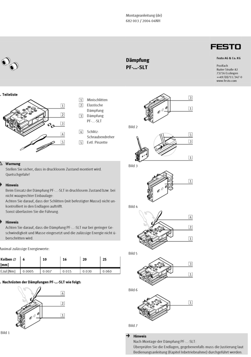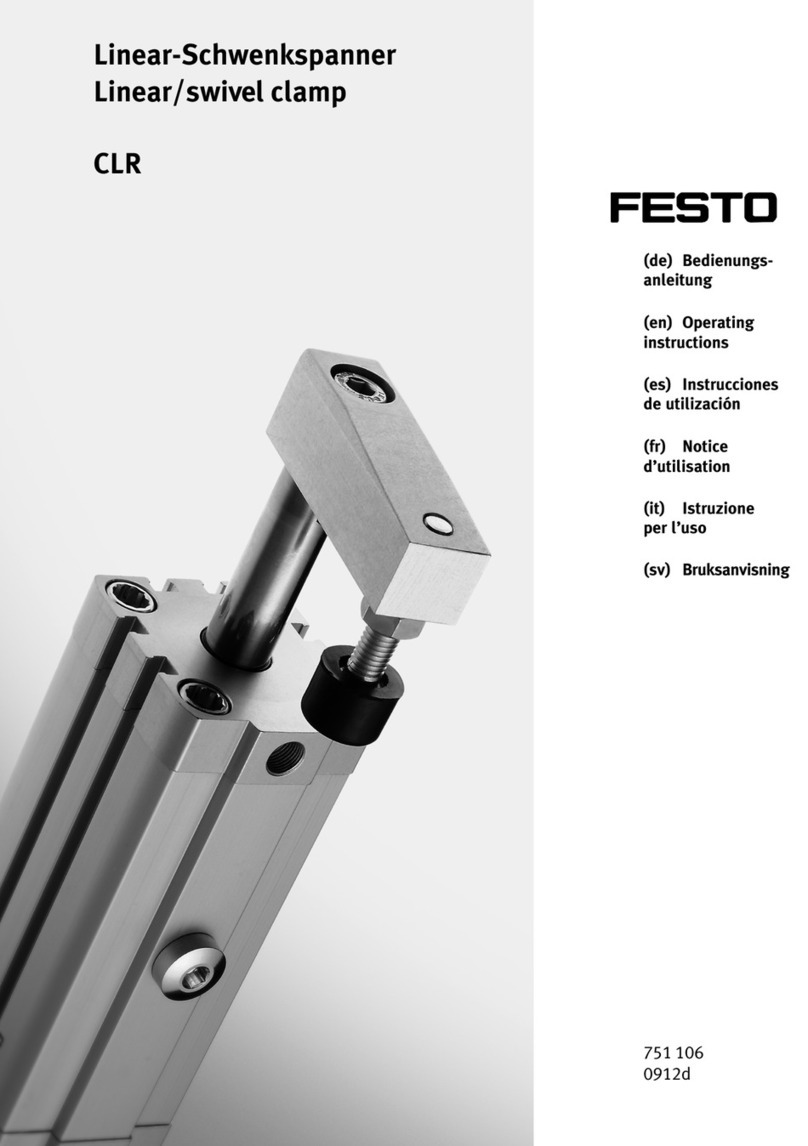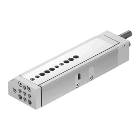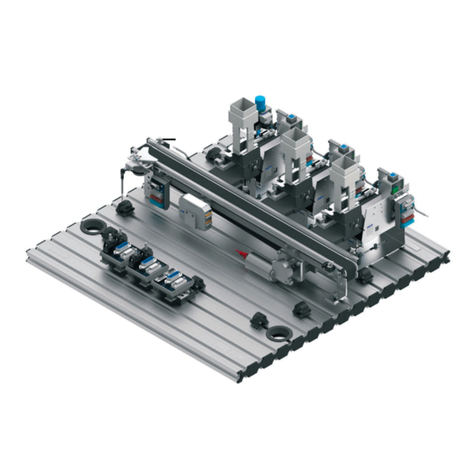
Adjusting product
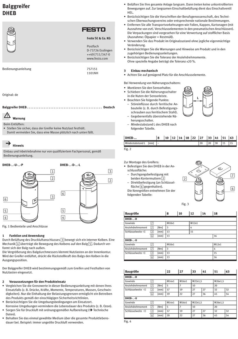
Fig. 3: Loosen lock nut
1. Position the mass to be cushioned at the intended end position.
2. Loosen the lock nut on the side of the cross-hole nut.
3. Adjust the position of the stop element in accordance with the mounting.
When mounting in drilled hole When mounting in thread
Turn the loaded lock nut in the desired direc-
tion. If necessary, hold the stop element
against the cross-hole nut.
Turn the cross-hole nut in the desired direc-
tion.
One revolution corresponds to approx. 1 mm stroke change.
4. Fix the position of the stop element. At the same time, tighten the lock nut on
the side of the cross-hole nut.
5.1 Mounting
5.2 Aligning product
–Observe the axial direction of force of the moving mass to the axis of the shock
absorber.
–The mass must contact the piston rod over a wide area.
Force direction, max. deviation Alignment of the mass
Tab. 5: Permissible axial force direction and alignment of the moving mass
5.3 Mounting accessories
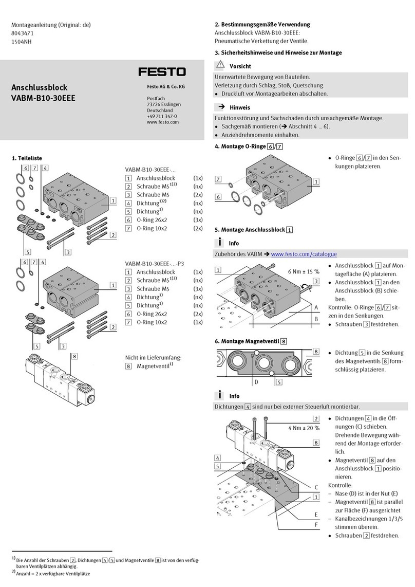
Mounting optional proximity switch
Fig. 4: Mounting proximity switches
Slot for proximity switch
Proximity switch (optional)
•Place the proximity switch in the slot and fasten it in accordance with the end
position of the shock absorber.
6 Commissioning
6.1 Executing test run
1. Start the test run at the drive at reduced velocity.
2. If necessary, readjust the position of the stop element.
3. Gradually increase the velocity of the drive to the operating value in steps.
ÄIf set correctly, the end position is reached without a hard stop.
With hard stop:
–Reduce the impact velocity if necessary.
–Check function and design of the stop element.
6.2 Notes on operation
Energy absorption
• Only use the shock absorber within the permissible range of 25% to 100% of
the maximum energy absorption è 10 Technical data.
Recommendation: use the shock absorber within the optimum range from
50% to 80% of the maximum energy absorption.
Energy absorption Note
0 … 25% Unfavourable; fluid leakage at the shock absorber may be
increased
25 … 50% Permitted
50 … 80% Optimal
80 … 100% Permitted
> 100% Impermissible
Tab. 6: Energy absorption of the shock absorber
Cushioning effect
The viscosity of the hydraulic fluid declines over its operating life due to the
generated friction heat. This can reduce the cushioning effect.
7 Maintenance
Maintenance interval Maintenance work
Every 2 million load changes Check shock absorber:
–sealing, no fluid leakage
–Cushioning distance s è 10 Technical data
In case of leakage, hard stop or cushioning distance too short:
replace shock absorber.
Every 5 million load changes Replace rubber buffer.
Every 10 million load changes Replace shock absorber.
Tab. 7: Maintenance schedule
The hydraulic fluid in the shock absorber cannot be topped up or changed.
The shock absorber cannot be repaired.
7.1 Replacing shock absorber
Fig. 5: Replacing shock absorber
Shock absorber
Spanner flat
Nut for securing the shock absorber
Stop plunger
Connecting clip
1. Release the load on the stop plunger 6.
2. Loosen the nut 3 on the shock absorber.
3. Unscrew the shock absorber, if necessary with a tool on the spanner flat.
4. If the connecting clip aA was removed with the shock absorber, press the
connecting clip on the new shock absorber.
5. Screw in the new shock absorber to the stop.
6. Tighten the nut 3 to the tightening torque.
Size 5 7 8
Nut 3
Tightening torque
[Nm] 2 3 5
Tolerance ± 20%
7. Actuate the stop plunger slowly until it reaches the end position and then
release the load.
ÄThe connecting clip clicks into place.
8Fault clearance
Malfunction Possible cause Remedy
Leakage/fluid leakage Shock absorber faulty Replace shock absorber.
Noisy impact at the start of the
stroke
Rubber buffer worn Replace rubber buffer
(YSRWJ-7/8 only).
Hard stop in the end position Stop element overloaded Reduce impact velocity or
check the layout of the stop
element.
Shock absorber faulty Replace shock absorber.
Malfunction during position
sensing
Incorrect position of proximity
switches
Correct position of proximity
switches.
Incorrect proximity switch type
used
Only use proximity switches
type SME/SMT-8-...-B.
Proximity switch defective Replace proximity switch.
Ferritic parts in the vicinity of
the proximity switch
Use parts made from non-mag-
netic materials.
Tab. 8: Fault clearance
9Dismantling and disposal
CAUTION
The product contains pressurised hydraulic fluid that can escape in an uncon-
trolled manner if the housing is damaged.
The hydraulic fluid can injure people's eyes and skin and damage the environ-
ment.
• Have the product disposed of by a qualified waste disposal company.
• Do not destroy the product in order to drain the hydraulic fluid.
