Rottler HP 7A User manual

27.08.2015


ORDERING PROCEDURE
Contact your regional Rottler sales rep for assistance in ordering optional equipment, replacement parts,
or tooling.
If you are unable to contact your regional Rottler sales rep, call the factory at 253-872-7050 and ask to
speak to the parts sales specialist.
Have the following information handy to expedite the ordering process:
1. Your name, business name, and contact number
2. Customer number
3. If you don’t have a customer number, your billing address
4. Shipping address if different from billing address
5. Machine model and serial number
6. Part number and description of what you want to order
7. Preferred method of shipment
8. You may also contact us via e-mail with the above information. Send e-mail requests to:
In some cases you may be requested to send a photo of the part you are ordering if it is a replacement
part, or doesn’t appear in the database.
If you are unsure which part you need to order, contact our service department and ask to speak to one of
our service consultants. They will assist you in determining which part you require.
THERE IS A MINIMUM ORDER OF $25.00
MANUAL SECTIONS
INTRODUCTION
INSTALLATION
SAFETY
CONTROL DEFINITIONS
OPERATING INSTRUCTIONS
MAINTENANCE
TROUBLESHOOTING
MACHINE PARTS
OPTIONS
MSDS


Section 1 Introduction HP7A Manual
www.rottlermfg.com
1-1
INTRODUCTION
READ THE SAFETY CHAPTER BEFORE INSTALLING MACHINE. THOROUGHLY UNDERSTAND
ALL SAFETY ISSUES BEFORE OPERATING MACHINE.
ATTENTION OWNER/BUSINESS MANAGER
To validate the warranty on your new Rottler machine, please be sure to sign
and complete the “Installation Report” located in the Installation Chapter of this
manual.
We suggest that the new user of the HP7A read the CONTROL DEFINITIONS to get an idea how the
machine operates.
The Operating Instructions chapter should be read in order to familiarize the user with the actual button
pushing sequences required to carry out a job. These chapters in the manual should be considered
an introduction. As the operators of the HP7A series machines gain experience with using the different
functions of the machine, complicated setups and programs will make more sense.
The rest of the manual contains information and part number reference on xtures, cutting tools, and
machine maintenance. The operator should read and become familiar with these areas as well.

Section 1 Introduction HP7A Manual
www.rottlermfg.com
1-2
Description
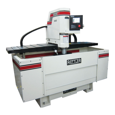
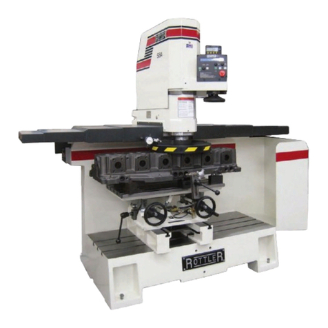
The model HP7A Honing Machine is a wet, complete cylinder block and general purpose-honing
machine. A totally enclosed AC motor driving a belt and gear reduction drive mounted within a rocker arm
arrangement supplies Hone rotating power. The honing head is driven through a universal joint.
An air cylinder with a hydraulic check system provides stroking power. Stroking may also be manually
operated.
A Windows based touch screen panel provides easy and convenient control of the HP7A. Block programs
can be created and stored to memory for later recall, providing a quick set up for honing common blocks.
All preferences such as dwell setting, cross hatch angle, and honing loads are automatically set up when
a block program is selected at time of machine set-up.
The support carriage is mounted on linear rails to provide simple and easy hole-to-hole setup.
Convenient devices are provided to properly control honing operations and provide easy handling.
A ‘V’ xture is provided, which efciently holds V-6/V-8, and in-line blocks for honing. Optional clamps are
available to clamp most any kind of in-line block or similar work piece.
Fixtures are available for doing large industrial engine sleeves.
A splash tank is located within the main frame and a coolant pump tank is located under the machine. A
button is provided on the control panel to operate the coolant system.
Disclaimer
The HP7A Manual (henceforth to be referred to as the “Manual”) is proprietary to Rottler Manufacturing
LLC. (“Rottler Manufacturing”) and no ownership rights are hereby transferred. No part of the Manual
shall be used, reproduced, translated, converted, adapted, stored in a retrieval system, communicated or
transmitted by any means, for any commercial purpose, including without limitation, sale, resale, license,
rental or lease, without the prior express written consent of Rottler Manufacturing.
Rottler Manufacturing does not make any representations, warranties or guarantees, express or implied,
as to the accuracy or completeness of the Manual. Users must be aware that updates and amendments
will be made from time to time to the Manual. It is the user’s responsibility to determine whether there
have been any such updates or amendments. Neither Rottler Manufacturing nor any of its directors,
ofcers, employees or agents shall not be liable in any manner whatsoever to any person for any loss,
damage, injury, liability, cost or expense of any nature, including without limitation incidental, special,
direct or consequential damages arising out of or in connection with the use of the Manual.
Limited Warranty
Rottler Manufacturing Company Model HP7A parts and equipment is warranted as to materials and
workmanship. This limited warranty remains in effect for one year from the date of delivery, provided the
machine is owned and operated by the original purchaser and is operated and maintained as per the
instructions in the manual.
Tools proven to be defective within the warranty period will be repaired or replaced at the factory’s option.
The products are warranted upon delivery to conform to their published specications and to be free from
defects in material and workmanship under normal use for a period of one year from shipment. Should a
product not be as warranted, Rottler sole obligation shall be, at its option, to repair, correct or replace the
product or to refund the amounts paid for the Product upon its return to a location designated by Rottler.
Section 1 Introduction HP7A Manual
www.rottlermfg.com
1-3
No warranty shall extend to rapid wear Products (including tooling) or to Products which have been
subject to misuse (including any use contrary to Rottler instructions), neglect, accident (including during
shipment), improper handling or installation, or subject to any modication, repair or service not certied
by Rottler. Rottler shall not be liable for any consequential, direct or indirect damages or for any other
injury or loss. Buyer waives any right, beyond the foregoing warranty, to make a claim against Rottler.
No warranty is provided for any Products not paid in full.
Merchandise cannot be returned to Rottler without prior approval. Customer must contact the Order
Department or representative to get approval and to be issued a Return Goods Authorization number
(RGR#). Merchandise authorized for return must be returned prepaid. If merchandise is returned with
shipping charges collect, the actual amount of these charges may be deducted from any credit which may
be due the customer. The RGR # assigned by the Order Department should be written on the shipping
label and must appear on a copy of the invoice(s) covering the original shipment. This invoice copy
must be included in the box with the parts. Shipment must contain ONLY those items on the RGR as
approved for return. Merchandise must be received within 10 days of the date of RGR or the RGR will be
canceled. All returned merchandise may be subject to a 20% restocking fee on under $1,000.00 amount
or 10% on any items over $1,000.00. Parts or tooling over 30 days old are considered as customer
property and can only be returned with prior written approval from Rottler Corporation Management and/
or Shipping Department.
The issuance of a RGR DOES NOT guarantee credit - it is only authorization for the return of the
goods. Credit for return merchandise is at the sole discretion of Rottler. Credit will be issued only after
inspection of returned goods.
Tools proven to be defective within the warranty period will be repaired or replaced at the factory’s option.
We accept no responsibility for defects caused by external damage, wear, abuse, or misuse, nor do
we accept any obligation to provide compensation for direct or indirect costs in connection with cases
covered by the warranty.

Section 1 Introduction HP7A Manual
www.rottlermfg.com
1-4

Section 2 Installation HP7A Manual
www.rottlermfg.com
I
INSTALLATION
Contents
ROTTLER HP7A INSTALLATION REPORT ................................................................2-2
Installation Procedure.................................................................................................2-6
Location................................................................................................................................. 2-6
Unpacking ............................................................................................................................. 2-6
Leveling ................................................................................................................................. 2-6
Air Supply.............................................................................................................................. 2-6
Coolant .................................................................................................................................. 2-6
Power Supply........................................................................................................................ 2-7
Grounding..........................................................................................................................................2-7
Single Phase Electrical Hook-Up ........................................................................................ 2-8

Section 2 Installation HP7A Manual
www.rottlermfg.com
2-1
ATTENTION OWNER/BUSINESS MANAGER
To validate the warranty on your new Rottler machine, please be sure
to sign the installation report after the installation technician has
installed the machine and veried the machine is operating correctly
and given the operators operation and maintenance training.
Thank you for your cooperation and the opportunity to be of service
to you.
ROTTLER MANUFACTURING

Section 2 Installation HP7A Manual
www.rottlermfg.com
2-2
Route to: Service Mgr Andy Machine Packet File
HP7A Installation Report Rev 08202015
ROTTLER HP7A INSTALLATION REPORT
ROTTLER MANUFACTURING MUST HAVE THIS REPORT RETURNED TO
PROPERLY QUALIFY WARRANTY ON EQUIPMENT
Customer:__________________________________ Address:_______________________________________
City:__________________________________ State:_____ Zip:____________ Phone:________________
Machine Model:______________ Serial Number:___________ Representative:________________________
MACHINE INSTALLATION: Electrical information MUST be complete to validate this report.
Customer responsibility prior to the arrival of Rottler Sales/Service technician. Please
Initial each item when it is completed.
VERY IMPORTANT: Modern design machines contain electronic low voltage circuitry
that provides great advantages and a better machine life. BUT, you must have an
excellent, stable, isolated power supply along with an isolated ground. If not, electrical
noise problems are likely to interfere with machine operation unexpectedly.
Customer is responsible for providing electricity to machine in a manner that meets the local electrical code
requirements.
______Remove machine from truck. Weight: 2,500 lbs.
______Provide solid foundation for machine.
______Remove xturing and misc. from machine and clean.
______Install machine on foundation with jack pads under jacking bolts.
______Level machine. When level all leveling bolts should have equal pressure on them.
______This machine requires between 208 and 240 Volts AC, Single Phase, 50/60 Hz, isolated power supply.
Measure the incoming voltage between L1 and L2. Measure the incoming AC voltage at least twice
during installation.
L1 to L2 __________ VAC L1 to L2 ___________VAC
______This machine should be externally breakered at 20 Amps, continuous draw.
______Measure each leg of the incoming supply to ground.
L1 to ground ___________VAC L2 to ground__________VAC
Neutral and machine ground are not the same thing. You should measure an open
circuit between Neutral and ground.
IF VOLTAGE IS OUTSIDE THE CORRECT RANGE AT ANY TIME THE MACHINE
WILL NOT OPERATE PROPERLY AND MAY BE DAMAGED.

Section 2 Installation HP7A Manual
www.rottlermfg.com
2-3
_______Briey describe the isolated ground connection to the machine you have made: (Instructions to make a
correct isolated ground are included in the operating manual)
__________________________________________________________________________________
__________________________________________________________________________________
__________________________________________________________________________________
______Air of the proper pressure and capacity connected to the machine 5.7 cu. Ft./min at 100 PSI. Air supply
must be free from oil and water. Oil or water will damage electrical and air components.
When applying air to the machine for the rst time, the Rocker Arm may move up
rapidly as air lls the stroking cylinder. Make sure all body parts are free of machine
parts.
______Customer should attempt to have junk work piece available.
______Make sure coolant will be available for set up on wet machine.
______Have the operator read through the operation manual before training begins. This will help him be familiar
with the button pushing sequences. Have the operator read through the manual again after training and
some of the sequences will make more sense.
______The system is protected by fuses located on the circuit board in the rear enclosure. Show customer where
they are located and conrm that spare fuses were shipped with machine.
______Clean any rust inhibitor from the machine surfaces. Slide the spindle base from side to side continually
cleaning the machine base until all inhibitor is removed.
______Explain the coolant ltration system and necessity of maintenance to that system.
______Explain to the customer that the injection oiler is set to oil one (1) drop every 2 minutes of spindle
operation. The timer is reset when the machine is turned off. The HP7A will not use oil in the reservoir
very rapidly.
MACHINE START-UP
______BEFORE turning power on to the machine. Check all wires for security by using the correct screw driver
and turning CW until movement stops. Stranded wire can “spread” slightly from vibration during transport.
When starting the machine for the rst time, it may move out of control. Make sure all
hands are clear of machine parts. Be ready to press the Emergency Stop button if
needed.
______Turn Main power on at the power switch located on the rear enclosure.
______If any of the fuses blow, replace them, then call factory if further assistance is needed.
MACHINE MOVEMENTS
Remove hone head from machine for the following procedures.
______Make sure there is nothing obstruction the full travel of the rocker arm.
______Explain all movements of the machine.

Section 2 Installation HP7A Manual
www.rottlermfg.com
2-4
INSTRUCTING THE OPERATOR:
______Point out safety factors to customer and operator. Do not push any buttons without thinking safety rst.
______Explain and demonstrate the following controls and functions:
______START SCREEN PROGRAM SELECT BUTTON
______PROGRAM SELECT BUTTONS
______OPERATION SCREEN PROGRAM SELECT BUTTON
______MANUAL MODE BUTTON
______PLATEAU MODE 1 & PLATEAU MODE 2 BUTTONS
______FINISH MODE BUTTON
______ROUGH MODE BUTTON
______CYCLE START BUTTON
______COOLANT PUMP BUTTON
______MANUAL FEED BUTTON
______SHORT STROKE BUTTON
______BOTTOM DWELL BUTTON
______TOP DWELL BUTTON
______AUTO CROSS HATCH BUTTON
______+ & - BUTTONS FOR ROUGH, FINISH, & STOP DELAY VALUE BOXES
______+ & - BUTTONS ON LOAD GRAPH FOR ROUGH & FINISH LOAD
______0 FEED BOX
______AUTO SHORT STROKE IN ROUGH AND FINISH MODE
______AUTO DWELL IN ROUGH AND FINISH MODE
______PLATEAU MODE OPERATION
______AUTO CROSS HATCH FUNCTION
______STROKING SPEED CONTROL
______E-STOP SWITCH
______Explain Bleeding of the Hydraulic System.
______Check manual operation of the Feed Wheel by rotating with your hand.
______Demonstrate loading and roll over of V8 block.
______Demonstrate in-line block clamp system.
______Explain Optional block hold down arrangements.
______Supervise the operator loading, cycling and unloading the block.
______Develop the best block handling system you can for his shop.
______Consider a block coolant drain area.
______Examine several V8 blocks at the lower cylinder / bearing cap area and explain to the operator the
necessity of setting the lower stop for maximum over stroke.
______Explain the ABSOLUTE requirement for complete relief below the cylinder, which may include hand
grinding.
______Demonstrate removal and cleaning of cone in hone head.
______Explain all stone options as well as hone head options.
______Load a block into the cradle and thoroughly explain the lower stop setting method.
______Set the upper limit cycle the hone in the cylinder, demonstrating the stroking speed control.
______Demonstrate the proper use of the load meter and proper operator responses for both Rough and Finish
modes.
______Explain to the operator the methods for the fastest stock removal.
______Explain the cause and cure of bad geometry and improper stone cutting.
______Explain “breaking” the stones in.
______Demonstrate proper stone dressing (refer to manual).
______Explain the importance of maintaining the proper coolant mix.
______Explain the importance of keeping the coolant clean.
______Review the necessity of proper stone to coolant relationship.
______Again review the operator manual, including all safety and emergency stop procedures.

Section 2 Installation HP7A Manual
www.rottlermfg.com
2-5
MAINTENANCE SECTION
______Review machine Lubrication per manual.
______Demonstrate emptying the water trap.
______Review coolant changing.
______Review lter and lter paper changing.
______Review lling oil reservoir.
______Demonstrate checking and adding oil to the upper gear box.
______Show operator hydraulic reservoir and adding the proper hydraulic oil.
______Show operator the location of the shear pin on the driven pulley inside the Rocker Arm. Locate spare
Shear Pin that was sent with machine and advise operator of its location.
General remarks on machine performance, adjustments as received and any further organization or parts
required to complete the set up:
____________________________________________________________________________________
____________________________________________________________________________________
____________________________________________________________________________________
____________________________________________________________________________________
____________________________________________________________________________________
____________________________________________________________________________________
____________________________________________________________________________________
____________________________________________________________________________________
____________________________________________________________________________________
____________________________________________________________________________________
Instructions given to: __________________________________________________________________
Sales/Service Engineer: _________________________________________________Date___________
Shop Foreman/Superintendent or Owner: ___________________________________Date___________

Section 2 Installation HP7A Manual
www.rottlermfg.com
2-6
Installation Procedure
Location
The productivity of this machine will depend to a great extent on its proper initial installation, particularly
the means by which cylinder blocks are lifted into the machine as well as the material handling to and
from other operations in your shop.
The proper loading arrangement and location for your HP7A machine is extremely important.
A slow travel (6’ to 10’ per min.) power hoist, operated from either a bridge crane or a jib crane
arrangement works very well. A 1000-lb. hoist is generally adequate for lifting the engine block. An air
hoist with speed control makes an ideal method for fast, convenient loading.
If some production honing with this machine is anticipated, and the cylinder blocks are not directly loaded
and unloaded from a conveyor, we would recommend considerable attention be given to the crane so that
it covers an adequate area to allow the operator to back up and remove cylinder blocks without cluttering
up his own area. If two machines are to be operated by one operator, we recommend that the open faces
be placed at right angles to each other, with the machines approximately three feet apart.
Unpacking
Carefully uncrate the HP7A Machine. Remove all equipment in splash tank except the ‘V’ xture frame.
Completely clean these articles with solvent, also clean the lower travel limit stop rod, Rust inhibitor is
applied to the machine at the time of shipment and must be removed before operating the machine.
Leveling
Four cap screws and jam nuts are provided with the machine for leveling. Insert the screws from the
bottom of the base. Place the jam nuts on top of the threaded hole in the base.
Using a precision level, level the upper table within .002” per foot in both directions (Except favor the high
setting to the front for best coolant return).
Air Supply
The HP7A machine requires 5.7 cubic feet/minute at 100 PSI compressed air (a minimum 1 HP air
compressor output).
Attach air supply to the lter regulator on the rear right side of the splash tank. Push and hold the oat
clamp button located on the front of the carriage. While holding the push button adjust the air regulator to
100 PSI (Push regulator knob down to set, pull up to lock).
Note: To assure a long service life for your HP7A machine the air supply must be moisture free. If
there is any doubts about the air supply install a water trap.
Coolant
Refer to the Coolant section in Chapter 5 of this manual for proper coolant types and mixes.

Section 2 Installation HP7A Manual
www.rottlermfg.com
2-7
Power Supply
Disconnect all power before servicing this machine. Failure to do
so could result in electrical shock.
This machine has the following power requirements:
208 to 240 VAC
Single Phase
50 or 60 Hertz
20 amps
(See wiring diagram for the HP7A Hone).
See illustration below for correct connection of “measured” incoming power. Connect single phase wiring
to the main rear enclosure, located on the right rear of machine base. The connection point for power
is located inside the enclosure. The connection termination point is located on the left hand side of the
electrical panel about half way up. Connect L1 to the number 2 terminal on the power switch, L2 (neutral)
to the number 4 terminal on the power switch. Attach wire from the grounding rod to the third terminal on
the terminal block.
Important: Electrically connect in accordance with national and local electrical codes.
Note: This machine requires the use of an electrical disconnect switch.
This machine cannot be run on 440 volts. A transformer must be
installed if 440 volts must be used.
Grounding
This machine must be connected to
a good earth ground rod. A 6 foot,
1/2” diameter, 15 OHM, Copper
grounding rod driven into the earth
next to the machines is preferred. Not providing
a grounding rod could void factory warranty.

Section 2 Installation HP7A Manual
www.rottlermfg.com
2-8
Single Phase Electrical Hook-Up
L1 and L2 power lines are attached to the power switch. Power supply ground wire goes to ground block.
See electrical diagram for more detail.
Wire in accordance with local and national codes.

Section 2 Installation HP7A Manual
www.rottlermfg.com
2-9

Section 3 Safety HP7A Manual
www.rottlermfg.com
I
SAFETY
Contents
Safety Information.......................................................................................................3-1
Safety Instructions for Machine Use .................................................................................. 3-1
Electrical Power.................................................................................................................... 3-3
Machine Operator ................................................................................................................. 3-4
Emergency Procedure ......................................................................................................... 3-5

Section 3 Safety HP7A Manual
www.rottlermfg.com
3-1
Safety Information
For Your Own Safety Read This Instruction Manual Before Operating This Machine.
This is the safety alert symbol. It is used to alert you to potential personal injury hazards.
Obey all safety messages that follow this symbol to avoid possible injury or death.
DANGER indicates an imminently hazardous situation which, if not avoided,
will result in death or serious injury.
WARNING indicates a potentially hazardous situation which, if not avoided,
could result in death or serious injury.
CAUTION indicates a potentially hazardous situation which, if not avoided,
may result in minor or moderate injury.
CAUTION used without the safety alert symbol indicates a potentially hazardous
situation which, if not avoided, may result in property damage.
Safety Instructions for Machine Use
This machine is capable of causing severe bodily injury
ONLY A QUALIFIED, EXPERIENCED OPERATOR SHOULD OPERATE THIS MACHINE. NEVER
ALLOW UNSUPERVISED OR UNTRAINED PERSONNEL TO OPERATE THE MACHINE. Make sure
any instructions you give in regards to machine operation are approved, correct, safe, and clearly
understood. Untrained personal present a hazard to themselves and the machine. Improper operation will
void the warranty.
KEEP GUARDS IN PLACE and in proper working order. If equipped
with doors, they must be in the closed position when the machine is in
operation.
KEEP WORK AREA CLEAN. Cluttered areas and benches invite accidents.
Table of contents
Other Rottler Industrial Equipment manuals

Rottler
Rottler EM69P CNC 5 AXIS User manual

Rottler
Rottler SG80AII User manual

Rottler
Rottler SA Series User manual

Rottler
Rottler SM Series User manual

Rottler
Rottler VR9 User manual

Rottler
Rottler SG8 User manual

Rottler
Rottler SG9A User manual

Rottler
Rottler P69 User manual

Rottler
Rottler H85A User manual

Rottler
Rottler SG10XY User manual
Popular Industrial Equipment manuals by other brands

Rodix
Rodix FC-42-DC Plus quick start guide

Axon
Axon TASER 7 quick start guide

MKS
MKS Ophir FluxGage user manual

Potter
Potter NGP-300D Installation, operation & service manual

Midwest Specialties
Midwest Specialties FlexArm A-32 Installation & operation manual

TriangleTube
TriangleTube PRESTIGE Excellence Series manual