Mounting The Operator
1/ Close the door, measure the centre of the door and mark this position on the
door and the frame header. Note: check that the door-frame header is securely
fixed at the centre and make good with additional fixings if necessary.
2/ Fix the C-rail fixing bracket to the lintel, door header, or ceiling, as shown in
Fig 1 or 2 The ideal position is 50 - 100mm above the top edge of the door.
3/ Place a carton on the floor to protect the motor casing and attach the C-rail to
the front fixing bracket as shown in Fig 4
4/ Raise the motor head and support it either by using a strap from the beams or
a pair of steps as in sketch as shown in Fig 5
5/ Open the door and align the C-rail track with the centre of the door and adjust
the motor height to give a clearance of approx 30mm to 60mm between the C-rail
track and the face of the door. The motor head may now be fixed to the ceiling
with the brackets provided. (for model TM80 refer fig 3 on page 7 of the
manufacturers installation manual for fixing details) Note: If you have a high
ceiling it may be necessary to extend the motor fixing brackets.
6/ Disengage the black sliding trolley from the chain drive (by pulling the manual
release cable forward) and slide the trolley along the track towards the door.
7/ Fix the door arm bracket to the top edge of the door as shown below. Four M6
self tapping screws & washers are provided for use on steel doors. For timber or
G.R.P. doors use M8 x 40mm coach screws & washers.
8/ Disable the original manual latching system on the door, (the motor will
automatically secure the door at the top when closed)
Note: Our Securi-Dor AP2000 multi-point locking system may be fitted to provide
additional security by automatically engaging the door's original manual latches
when closed.
Emergency Release Device
If your garage door is the only entrance you must provide a means of
opening the garage door from outside in the event of power failure.
Seip operators feature a Bowden cable operated emergency door-release device
to allow manual operation in case of power failure, this can be operated either
from inside the garage, or from outside by means of the original locking door
handle if you have a "vault type" garage (no personal access door)
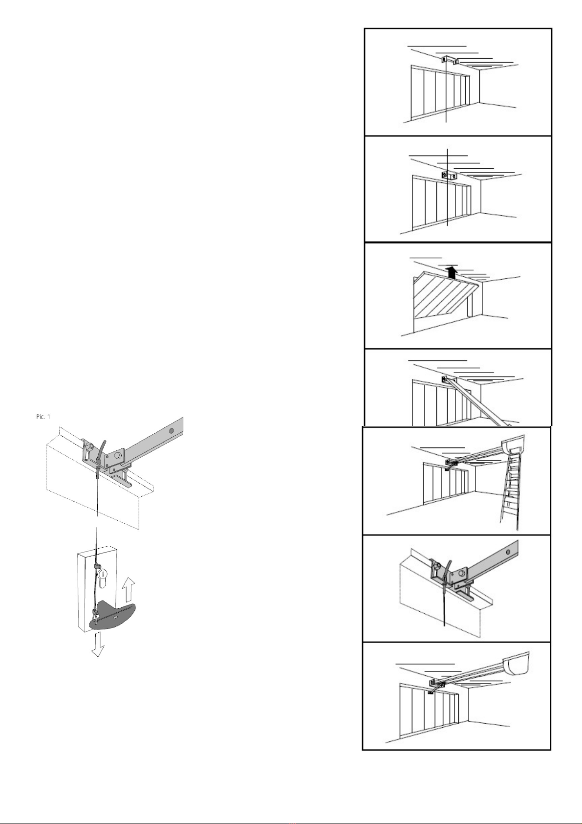
To enable the door to be released from
outside with a key the emergency
release cable should be connected to
the original locking door handle as
follows:
Connect the emergency release cable
to the back of the door's original handle
so that when the handle is unlocked and
turned from outside it pulls the cable
downwards. The sketch (Pic1) is only a
guide as door handles vary according to
the make of door.
Note: Do not leave the garage and
close the door until you have
tested the operation of the
emergency release from outside.
Get someone to test for correct
operation of the handle & cable etc.
while you are inside.
If your garage has a personal
entrance door it is not necessary to
connect the emergency release cable
to the door handle as above
Note: we do not recommend using the red pull toggle supplied by the factory.
We recommend that you fit 4mm red sleeving (supplied) over the cable instead
and secure the end of the emergency release cable to a fixed point on the back
of the door garage, this will enable manual operation from inside by pulling the
cable.
Page 2 of 4
Fig 1
Fig 2
Fig 3
Fig 5
Fig 6
Fig 7
Fig 4


