Selec SP112 Series User manual

ATSEL HMI User Manual
ATSEL HMI User
Manual
(Version:2.02)
Selec Controls Pvt. Ltd.

ATSEL HMI User Manual
Content
Installation...........................................................................................................................1
Communication Protocol.....................................................................................................3
Address setting....................................................................................................................5
Animation esign..............................................................................................................13
Recipe...............................................................................................................................15
ata Transmission............................................................................................................17
Alarm.................................................................................................................................18
Multi Language..................................................................................................................22
History ata Record..........................................................................................................24
User Encryption.................................................................................................................29
Update Program by U Flash..............................................................................................34
QR Code...........................................................................................................................35
One HMI Multi PLCs..........................................................................................................37
Time Setting......................................................................................................................40
Installment.........................................................................................................................42
System Configuration........................................................................................................49
Internal Register of System...............................................................................................51
Printer Settings.................................................................................................................54

1
ATSEL HMI User Manual
Installation
imension for installation opening
SP112 series of HMI(SP112-GT70-S-CE and SP112-GT70-ET-CE)
SP112 – 192×138mm
Interface
SP112 interface
Cable layout:back side of the HMI

2
ATSEL HMI User Manual
COM ort connection
For SP112, COM port includes RS232 and RS485. The pins set up as below, pin 7/8 for
RS485 and pin 2/3/5 for RS232.
As for 4 Points terminal, A is set for RS485+,B RS485-, R is when using built-in 120Ω
resistance then to short connection R and A, it will be convenient for long-distance
communication.
Remark
: the pluggable terminal COM1 and the B9 COM1 share the same RS485
series port, thus they can’t be used at the same time.
HMI B9 Male Pluggable terminals
picture
interface
PIN
Pin efinition
interface
PIN
Pin definition
remark
picture
SP112 COM2 1 —— COM1 1 R 120Ω resistance
2 RS232 RX 2 A RS485+(A)
3 RS232 TX 3 B RS485-(B)
4 —— 4 PE Shielded ground
5 GN remark:The pluggable terminal COM1 and the B9
COM1 share the same RS485 serial port.
COM1 6 ——
7 RS485+(A)
8 RS485-(B)
9 ——

3
ATSEL HMI User Manual
Communication protocol
Function brief
Our HMI support many kinds of communication protocols, such as PPI, MPI,
Modbus, smart S7, Mitsubishi, Panasonnic, Omron, etc.
Series communication:
COM1(RS485)
SiemensS7-200/smart CPU)
SiemensS7-300 CPU)
All Modbus evices.
COM2(RS232)
Mitsubishi(Fx1, Fx2N, Fx3U)

4
ATSEL HMI User Manual
Panasonnic(Fp)
Omron(CP)
MO BUS(MO BUS-RTU MO BUS ASCII)
Ethernet communication:
MO BUS TCP(Server / client)
S7 communication(S7-200 smart)
Remark
: O ur HMI has set the function buttons for smart running & stop .
Connect with PLC
SP112 — Siemens
SP112 — Mitsubishi Fx1N/Fx2N ( B9) SP112 — Panasonic Fp
SP112 — Mitsubishi Fx2N/3U (8 pin circular hole) SP112— Omron CP
PPI/MPI
SP112
7 485+
8 485-
3 485+
8 485-
Fx1N/2NSP112
2 X
3 TX
5 GND
2 TXD
1 XD
3 GND
FpSP112
2 X
3 TX
5 GND
2 TXD
3 XD
1 GND
Fx3USP112
SG Shield
2 X
3 TX
SG Shield
4 TX-
1 X-
5 GND 2 X+
7 TX+
500Ω
500Ω
Cp
SP112
2 X
3 TX
5 GND
2 TXD
3 XD
9 GND
4 TS
5 CTS

5
ATSEL HMI User Manual
Address setting
Function introduction
1. RS485(Siemens S7-200)【PPI communication】same as S7 communication
Register
name
Address
format
Input range Remark
I dd.o 0.0~4095.7 bit: input mapping register
Q dd.o 0.0~4095.7 bit: output mapping register
M dd.o 0.0~4095.7 bit: bit memory
S dd.o 0.0~4095.7 bit: Sequence Control Relay
SM dddd.o 0.0~4095.7 word: special bit memory, SM0.0~SM4095.7
V ddddd.o 0.0~10239.7 bit: the bit of variable memory
IW dddd 0~4094 word: input mapping register, each word occupies two byte address
QW dddd 0~4094 word: output mapping register, each word occupies two byte address
MB dddd 0~4095 byte: bit register, each word occupies one byte address.
MW dddd 0~4094 word: bit register, each word occupies two bytes address.
M dddd 0~4092 double word: bit register, each word occupies four bytes address.
SB dddd 0~4095 byte: sequence control relay, each word occupies one byte address.
SW dddd 0~4094 word: sequence control relay, each word occupies two bytes address.
S dddd 0~4092 double word: sequence control relay, each word occupies four bytes address.
SMB dddd 0~4095 word: special bit memory, SMB0-SMB29 read only, each word occupies one byte address.
SMW dddd 0~4094 word: special bit memory, SMW0-SMW28 read only, each word occupies two bytes address.
SM dddd 0~4092 word: special bit memory, SM 0-SM 26 read only, each word occupies two bytes address.
VB ddddd 0~10239 Byte: variable memory
VW ddddd 0~10238 word: variable memory, each word occupies two bytes address.
V ddddd 0~10236 double word: variable memory, each word occupies four bytes address.
TV ddd 0~255 word: the current value of the timer.
CV ddd 0~255 word: the current value of the counter.
AIW dd 0~62 word: analog input, each word occupies two addresses.
AQW dd 0~62 word: analog output, each word occupies two addresses.
2. RS485-Siemens S7-300 (MPI communication)
Register Name Address format Input range remark
I dddd.o 0.0~1023.7 bit: input mapping register
Q dddd.o 0.0~1023.7 bit: output mapping register
M dddd.o 0.0~255.7 bit: bit memory
BX :dddd.o 1:0.0~99:32767.7 bit: the bit for the word in B block storage area. The block no. 0-99.
Each block word dddd with range 0-32767 and each word’s bit is 0-7.
IW dddd 0~1022 word: input mapping register, each word occupies two byte address
QW dddd 0~1022 word: output mapping register, each word occupies two byte address

6
ATSEL HMI User Manual
MW dddd 0~254 word: bit memory, each word occupies two bytes address.
M dddd 0~252 double word: bit memory, each double word occupies four bytes address.
BW :dddd 0:0~99:32766 word: B block storage area, block no. 0-99, each block word dddd with
range 0-32766. each word occupies two bytes address.
B :dddd 0:0~99:32764 double word: B block storage area, block no. 0-99, each block word
dddd with range 0-32764. each double word occupies four bytes address.
PIW dddd 0~1022 word: process image input area.
PQW dddd 0~1022 word: process image output area.
3. MO BUS
Register Name Address format Input range remark
0x ddddd 1~65536 bit: output coil.
1x ddddd 1~65536 bit: input coil, read only.
3x_bit ddddd. 1.0~65536.15 bit: the bit input register with 16 bit. Read only
4x_bit ddddd. 1.0~65536.15 bit: the bit output register with 16 bit.
3x ddddd 1~65536 word: the word with 16 bit what be input register. Read only.
4x ddddd 1~65536 word: the word with 16 bit what be output register.
3x_double ddddd 1~65535 ouble word: input register, high-low 16bits upside down with 3x double word,
read only
4x_double ddddd 1~65535 ouble word: output register, high-low 16bits upside down with 3x double word
Note:
d:decimal, the input range is 0~9.
o:octal, and the input range is 0~7.
:block number, the input range is 0-255.
:hexadecimal, and the input range is 0-15.
Word: it means that the register can only be used as a word.
ouble word: it indicates that the register must select 32 bits in the configuration
Bit: it means that the register can only be used as a bit.
Read only: it means that the register can only read but not be written in.
The Register Name supported by different device models may be different and
the range may vary. Please refer to the related technical documents of the
connected devices in detail.
*1 remark:in expanding mode, when input address, using “/” means connection and
using “#” means expanding mode. For example, 2/1#REGxxx means the second
connection No. 1 address REGxxx.

7
ATSEL HMI User Manual
4. Mitsubishi FX series
Fx2N
Register name bit/word Address format Max. address Mini. address
X bit OOO 377 0
Y bit OOO 377 0
M bit 3071 0
S bit 999 0
SM bit 8255 8000
T bit 255 0
C bit 255 0
word 7999 0
S word 8255 8000
TV word 255 0
CV word 199 0
32CV word 255 200
Fx3U
Register Name bit/word Address format Max. address Mini. address
X bit OOO 377 0
Y bit OOO 377 0
M bit 7679 0
S bit 4095 0
SM bit 8255 8000
T bit 255 0
C bit 255 0
word 7999 0
S word 8255 8000
TV word 255 0
CV word 199 0
32CV word 255 200

8
ATSEL HMI User Manual
5. Panasonic Fp series
Register Name bit/word Address format Max. address Mini. address
X bit OOO 377 0
Y bit OOO 377 0
R bit 7679 0
T bit 4095 0
C bit 8255 8000
L bit 255 0
T word 99999 0
L word 99999 0
FL word 99999 0
SV word 9999 0
EV word 9999 0
WX word 9999 0
WY word 9999 0
WR word 9999 0
WL word 9999 0
IX word 13 0
IY word 13 0
I word 32 0
6. Omron CP1H
Register Name bit/word Address format Max. address Mini. address
CIO_bit bit dddd. 6143.15 0.0
LR_bit bit ddd. 199.15 0.0
HR_bit bit dddd. 1535.15 0.0
AR_bit bit ddd. 959.15 448.0
M_bit bit ddddd. 32767.15 0.0
CIO word 6143 0
LR word 199 0
HR word 1535 0
AR word 959 448

9
ATSEL HMI User Manual
TC word 127 0
M word 32767 0
Fins
Register Name bit/word Address format Max. address Mini. address
CIO_bit bit dddd. 6143.15 0.0
WR_bit bit ddd. 199.15 0.0
HR_bit bit dddd. 1535.15 0.0
AR_bit bit ddd. 959.15 448.0
M_bit bit ddddd. 32767.15 0.0
CIO word 6143 0
WR word 199 0
HR word 1535 0
AR word 959 448
TC word 127 0
M word 32767 0
7. Address searching function
Click the search function of edition or shortcut key crtl+F then the address search
menu is popped up which can search the bit or word of the internal address and external
connection address, or the current scene and all the scenes, and supports the address
replacement at the same time.
Example
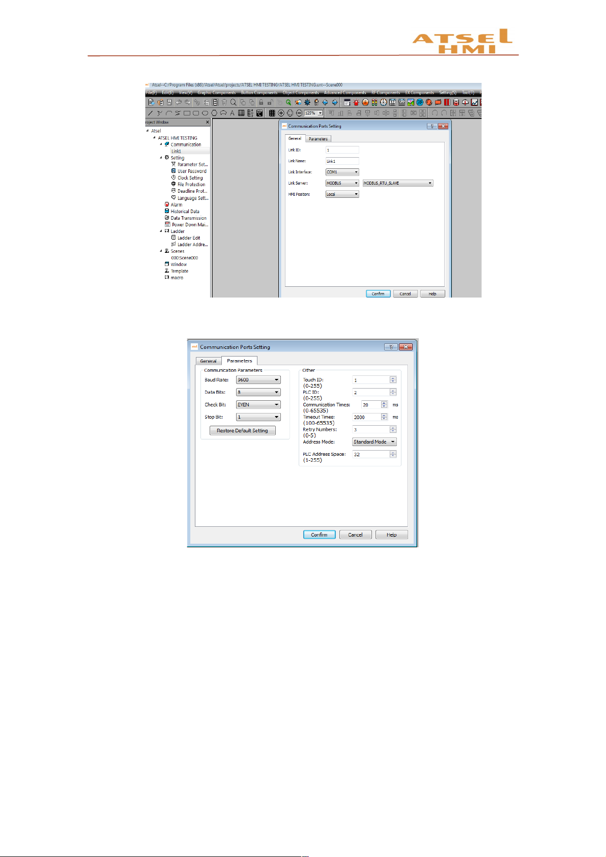
1. HMI’s communication parameters setting: set communication port--- mode
selection--PPI
10
ATSEL HMI User Manual
2. PPI communication parameters setting as showing in below chart.
3. Put a few bit buttons onto the screen and setting the written addresses of these bit
buttons Q0.0, Q0.1.

11
ATSEL HMI User Manual
4. The system block parameter setting interface of S7-200 program software is
shown as the following diagram
5. Connect the HMI to PLC through 485 communication cable and power them
together, then download the corresponding project to HMI. When click the components
on the screen, the corresponding PLC output points will be lighten.

12
ATSEL HMI User Manual
6. Address searching : Click the search function of edition or shortcut key ctrl+F to
pop up the search interface. You can search bit and word in the current scene or all of
the scenes. At the same time, you can replace the selected addresses, double-click the
corresponding addresses to pop-up corresponding control option of corresponding
scene.

13
ATSEL HMI User Manual
Animation design
Function introduction
Picture Dis lay function: To achieve the dynamic display of static pictures through
other ways, such as address control, time setting.
GIF icture: To set dynamic gif pictures. You can set the animation in the library, or
user-defined GIF files.
Bar Gra h: The value of the corresponding address is displayed by the bar graph.
Flow Block: Flow Block is used to simulate in animated pictures the liquid flow
status in pipeline. Whether a flow block is flowing is determined by the status of the
trigger, when the trigger is 1, the flow block is flowing, when the trigger is 0, the flow block
is static. The flowing speed is specified by user.
Dynamic Rectangle and Dynamic Circle: Their function is similar which changes
the position or size of graph according to the value of monitoring address, thus to show
real-time change of the monitor address on a dynamic basis.

14
ATSEL HMI User Manual
Example
1. Shining light (controlled by time)
Put a Picture isplay on scene, in the general page set the Total Status 2, Status
type to auto change with frequency being set 5 x 0.1s. In Label page, add an indicator
pattern from the Gallery to a status screen, in Visibility page set controlled by bit, When
the corresponding bit value to achieve the effective state the indicator pattern will be
displayed.
2. Liquid storage tank.
Put a image of Graphic Components, select a liquid storage tank from Gallery, and
drag into a Bar graph of Object components to cover the liquid area of tank.
3. Rotation motor
First put a picture and set as display when bit control value being 0, put a
similar GIF component and set as display when bit control value being 1. These two
components must be set the same size and same position(Use alignment function). Or
put a picture to be displayed when its bit control value being 0and put a Picture isplay,
set to automatically switch 0.1s, Then select two motor pictures with same shape but
different angle in the Gallery, set to display them when the bit control value being 1.

15
ATSEL HMI User Manual
4. Flow block
Add expand flow block at advanced components and set the corresponding address
for it.
5. Dynamic rectangle, Dynamic circle
In the Object components, add dynamic rectangle or dynamic circle and set the
corresponding address.
ynamic rectangle, for example, the data type is 16-bit integer, and the address is
ynamic circle, for example, the data type is 16-bit integer, and the address is set as
LW1. Then the value of LW1 is the X coordinate of the center of the circle. The value
of LW2 is the Y coordinate of the center of the circle, and the value of LW3 is the
radius of the circle.
Recipe Function
Function introduction
In manufacturing field, recipe describes proportion relation of different recipes, it's
the gather of some variables corresponding parameters setting value during production
process.
For example, a bread factory produces bread, there will be a basic ingredient recipe,
this recipe will list all ingredient lists that used for producing bread (for example
water,flour, sugar, egg, sesame oil etc.)Besides, also list all choosable ingredient lists (for
example fruits, kernel, chocolate chips etc.) These choosable ingredient can be added to
basic recipe to produce various breads. For example,sweet cake will use more
sugars,while low sugar cake will use less sugar. Here, we call the ingredient proportion
relation as recipe.
In ATSEL recipe editor function, one group recipe is one proportion relation. In the
table of editor, customers can match proportion relation among ingredients visually. Click
"Recipe Setting" of tool menu, then you can see recipe configuration dialog box, please
check as below:
1. Create a recipe group and name as bread.
2. Add the ingredients number of bread that is recipe length is 5.
3. Modify ingredients name and matched variable address.
4. Click save recipe and exit.

16
ATSEL HMI User Manual
Example
1. Project target
Realize the adjustment of different kinds of coffee ingredients, so that can complete the
coffee modulation by one key operation.
2. How to achievement
Click recipe control , add a new recipe group and set ingredients number of recipe,
each recipe contains different ingredients proportion, and then save the recipe.
Add the corresponding components and set corresponding variables to project scene,
and group index is modify Internal Register LW60802 can achieve switch-over of recipe

17
ATSEL HMI User Manual
group, If recipe index is Modify Internal Register LW60803 can achieve recipe switch-
over of recipe group.
Numerical input and display address of recipe ingredients is using the internal recipe
register address. Such as the above recipe, there are 8 ingredients, the system internal
address is RWI0-RWI7 from top to bottom if connects corresponding PLC address just
needs to input the corresponding variables, such as VW0, VW2, VW4 etc. Recipe’s
uploading, downloading or saving can be achieved in the function button.
ata transmission
Function introduction
ata Transmission is used for the data exchange between external device and HMI
or between device and device.
Click ata Transmission in Project Manager to pop up the data transmission list as
below.
1. Click "Add", you can add data transmission. At present, maximum number entries is
100. Triggered type is interval trigger and minimum time unit is 200ms, the data types
which can be transfered is bit, word, double word, and the maximum transmission data
size by each trigger is 100(bit, word, double word)
a)Interval: 1~100 (* 20ms )
b)Address type: bit, word, double word
c)Address length: 1~100, the data size of each transmission, unit is the type chosen at
"address type"
d)Source address/ estination address: the transmission direction is from source
address to destination address, this type of chosen register must be same as the address
set in "Address type".
2. After setting, click "confirm", add this set entry into the list.

18
ATSEL HMI User Manual
3.After adding, click close button exit, after downloading the configuration you can do
data exchange according to the set transmission type.
Alarm
Function Introduction
When triggering some events that should not be triggered during the operation of the
device, the system will make warning and record the time and content of the
corresponding events. The alarm is used to set the alarm information. Only the alarm is
configured, the alarm control and the dynamic alarm bar can be used normally.
1. Set the alarm information, firstly set the trigger condition
2. Record the real-time alarm: to show the real-time alarm data, alarm
scrollbar
3. System alarm setting: to set the display mode of overall pages alarm.
This manual suits for next models
2
Table of contents


