Selecon PLFRESNEL 1 MKII User manual

PLFRESNEL 1 MKII
QUICK START GUIDE

1
PLFRESNEL1 MKII LED Luminaire QuickStart Guide
TABLE OF CONTENTS
TABLE OF CONTENTS
IMPORTANT INFORMATION
Warnings and Notices ..................................................................................................................................... 2
Additional Resources for DMX512 ................................................................................................................ 2
Selecon Limited Three-Year Warranty............................................................................................... 2
PREFACE
About this Guide..................................................................................................................................................... 3
Product Descriptions .............................................................................................................................................. 3
INSTALLATION AND SET UP
Top Box Connections ............................................................................................................................................. 4
Power Requirements............................................................................................................................................... 4
Connecting Power .................................................................................................................................................. 5
Connecting to the DMX512 Network .................................................................................................................... 5
Mounting ................................................................................................................................................................ 6
Using Supplied C-Clamp ................................................................................................................................ 6
Pan and Tilt Adjustments ....................................................................................................................................... 7
Pan Adjustment ............................................................................................................................................... 7
Tilt Adjustment ............................................................................................................................................... 8
BEAM ADJUSTMENTS
Beam Adjustments.................................................................................................................................................. 9
Barndoor Assembly................................................................................................................................................ 9
OPERATION AND PROGRAMMING
LCD Menu Operation........................................................................................................................................... 10
LCD Menu System ............................................................................................................................................... 11
Security................................................................................................................................................................. 11
Locking Fixture ............................................................................................................................................. 12
Presets................................................................................................................................................................... 12
Editing Preset Names .................................................................................................................................... 12
Settings ................................................................................................................................................................. 12
TROUBLESHOOTING
Troubleshooting Guide ......................................................................................................................................... 14
QuickStart Guide PLFRESNEL1 MKII LED Luminaire
2IMPORTANT INFORMATION
IMPORTANT INFORMATION
Warnings and Notices
Additional Resources for DMX512
For more information on installing DMX512 control systems, the following publication is available for purchase
from the United States Institute for Theatre Technology (USITT), "Recommended Practice for DMX512: A Guide
for Users and Installers, 2nd edition" (ISBN: 9780955703522). USITT Contact Information:
USITT
315 South Crouse Avenue, Suite 200
Syracuse, NY 13210-1844
Phone: 1.800.938.7488 or 1.315.463.6463
www.usitt.org
Selecon Limited Three-Year Warranty
Selecon offers a three-year limited warranty of its luminaires against defects in materials or workmanship from
the date of delivery. A copy of Selecon three-year limited warranty containing specific terms and conditions
can be obtained from the Selecon web site at www.seleconlight.com or by contacting your local Selecon office.
When using electrical equipment, basic safety precautions should always be followed including the following:
a. READ AND FOLLOW ALL SAFETY INSTRUCTIONS.
b. Do not use outdoors.
c. Do not mount near gas or electric heaters.
d. Equipment should be mounted in locations and at heights where it will not readily be subjected to
tampering by unauthorized personnel.
e. The use of accessory equipment not recommended by the manufacturer may cause an unsafe
condition.
f. Do not use this equipment for other than intended use.
g. Refer service to qualified personnel.
SAVE THESE INSTRUCTIONS.
WARNING: You must have access to a main circuit breaker or other power disconnect device
before installing any wiring. Be sure that power is disconnected by removing fuses or turning the
main circuit breaker off before installation. Installing the device with power on may expose you to
dangerous voltages and damage the device. A qualified electrician must perform this installation.
WARNING: Refer to National Electrical Code® and local codes for cable specifications. Failure to
use proper cable can result in damage to equipment or danger to personnel.
WARNING: This equipment is intended for installation in accordance with the National Electric
Code® and local regulations. It is also intended for installation in indoor applications only. Before
any electrical work is performed, disconnect power at the circuit breaker or remove the fuse to avoid
shock or damage to the control. It is recommended that a qualified electrician perform this
installation.

About this Guide 3
PLFRESNEL1 MKII LED Luminaire QuickStart Guide
PREFACE
1. About this Guide
This Quickstart Guide is intended for a knowledgeable user to unpack, install, and use the PLFRESNEL1 MKII LED
Luminaire in a short time period. For the complete manual in PDF format, please visit our web site at:
www.seleconlight.com and click the user manual download link on the product page. The complete manual provides
you all information related to accessories, menu structures, DMX channel mapping/modes, and care for your new
luminaire.
Please read all instructions before installing or using this product. Retain this guide for future reference. Additional
product information and descriptions may be downloaded at www.seleconlight.com.
2. Product Descriptions
The document provides installation and operation instructions for the following products:
• PLFRESNEL1 MKII LED Luminaire (PLFR1MKII-03)
Note: All PLFRESNEL1 MKII LED Luminaires are universal voltage (100VAC to 240VAC, Auto-ranging).
:

QuickStart Guide PLFRESNEL1 MKII LED Luminaire
4INSTALLATION AND SET UP
INSTALLATION AND SET UP
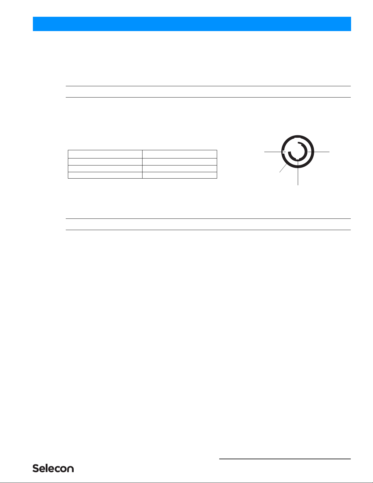
1. Top Box Connections
All PLFRESNEL1 MKII LED Luminaires are supplied with a "Top Box" for AC Input/Output and DMX512 Input/
Output Connections. Figure 1 shows the AC and DMX512 Input and Output (Thru) Connections.
Figure 1: PLFRESNEL1 MKII LED Luminaire Top Box Connections
2. Power Requirements
WARNING! The PLFRESNEL1 MKII LED Luminaire should be connected to a constant circuit or a relay device. It
should never be connected to a dimmer or circuit controlled by a dimmer.
The PLFRESNEL1 MKII LED Luminaire operates on 100 to 240 volts AC (+/- 10%, auto-ranging). The luminaire
contains an auto-ranging power supply. Depending on supply voltage, each luminaire can draw up to 140 Watts. The
maximum through current should not exceed 20 Amps*.
WARNING! *Maximum Allowable Input Current of 20 Amps (maximum power supply limit of 140 Watts). Do not
overload circuits! Must be supplied by a branch circuit protected by a maximum 20 Amp circuit protector. Doit
être alimenté par un circuit de dérivation protégé par un maximum de 20 ampères circuit protecteur. Do not
overload circuits!
IMPORTANT AC POWER CONNECTION NOTES:
a. Must be supplied by a branch circuit protected by a maximum 20 Amp circuit protector. Doit être
alimenté par un circuit de dérivation protégé par un maximum de 20 ampères circuit protecteur.
b. When using the daisy-chain connection method, ONLY connect PLFRESNEL1 MKII LED Luminaires
to AC Output Connection of PLFRESNEL1 MKII LED Luminaires. DO NOT CONNECT OTHER
TYPES OF LUMINAIRES OR DEVICES!
c. Use only approved cable types.
d. Do not overload circuits!
DMX512 Output/Thru
DMX512 Input
AC (Power) Output
AC (Power) Input
Multi-Conductor Top Box
to Luminaire Connection
Multi-Conductor Top Box
to Luminaire Connection
Side View 1
Side View 2
Connecting Power 5
PLFRESNEL1 MKII LED Luminaire QuickStart Guide
e. Do not connect PLFRESNEL1 MKII LED Luminaires to dimmed circuits.
f. The MAXIMUM allowable number of PLFRESNEL1 MKII LED Luminaires which can be 'daisy-
chained' on one power feed should not exceed ratings. DO NOT EXCEED!
3. Connecting Power
Note: Refer to Figure 1 on page 4 for AC Input and Output connections.
If the unit is supplied with an AC input cable, Table 1 describes how to connect power to your PLFRESNEL1 MKII
LED Luminaire . Field wiring of the PLFRESNEL1 MKII LED Luminaire is straight forward. A total of 3 wires/
conductors need to be brought to the unit. The following wiring scheme is required:
Table 1: PLFRESNEL1 MKII LED Luminaire AC Input
Connections
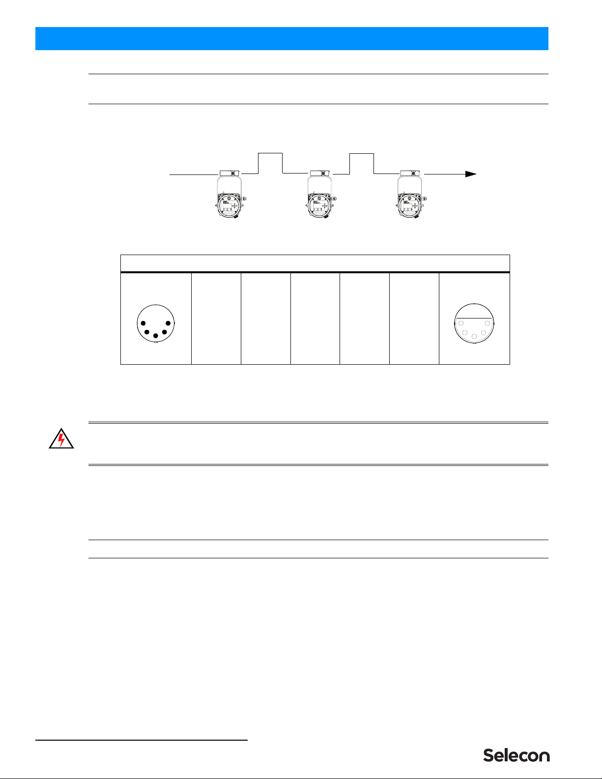
4. Connecting to the DMX512 Network
Note: Refer to Figure 1 on page 4 for DMX512 Input and Output/Thru connections.
Basic DMX512 installation consists of connecting multiple PLFRESNEL1 MKII LED Luminaires together (up to 30
luminaires) in "daisy-chain" fashion. A cable runs from the control console (or DMX512 control source) to the DMX
connector on the first PLFRESNEL1 MKII LED Luminaire. Another cable runs from the other DMX connector on
the first unit to a DMX connector on the next PLFRESNEL1 MKII LED Luminaire (or DMX512 device to be
controlled).
- Continued Next Page -
Wire Color Purpose
Brown Main / Line (100 to 240VAC)
Blue Neutral
Green/Yellow Ground
Neutral Main /
Ground / Earth
Line
AC Input Connector
(on back of unit)
QuickStart Guide PLFRESNEL1 MKII LED Luminaire
6INSTALLATION AND SET UP
Note: For more information on DMX512 networking and systems, refer to "Additional Resources for DMX512" on
page 2. For PLFRESNEL1 MKII LED Luminaire DMX Mapping, refer to the product user’s manual.
Figure 2: Connecting DMX512
5. Mounting
WARNING! Before attempting any installation or service, disconnect all power at power source. Dimming the
luminaire does not disconnect power. Installation and service should only be performed by a trained and qualified
professional.
Using Supplied C-Clamp
As illustrated in Figure 3 on page 7, at yoke assembly, thread clamp mounting bolt (with washers installed) through
center clamp mounting hole at top of yoke, through Top Box Assembly, and thread bolt into C-Clamp. Securely
tighten bolt (by hand) into clamp (but do not over-tighten).
Note: Top box will be able to swivel once bolt is tightened by design. DO NOT OVER-TIGHTEN!
DMX512 Connections
Data Thru
Cable Pinout
Male Conn
Pin 1
Common
(Drain)
Pin 2
Data (-)
Pin 3
Data (+)
Pin 4
Not Used
Pin 5
Not Used
Data In
Cable Pinout
Female Conn
1
2
3
4
5
1
2
3
4
5
DMX512
DMX512 (out from first
to second luminaire)
DMX512 (out to the next luminaire or
DMX512 controlled device)
PLFRESNEL1 MKII LED Luminaires
(from console or
control device)

Pan and Tilt Adjustments 7
PLFRESNEL1 MKII LED Luminaire QuickStart Guide
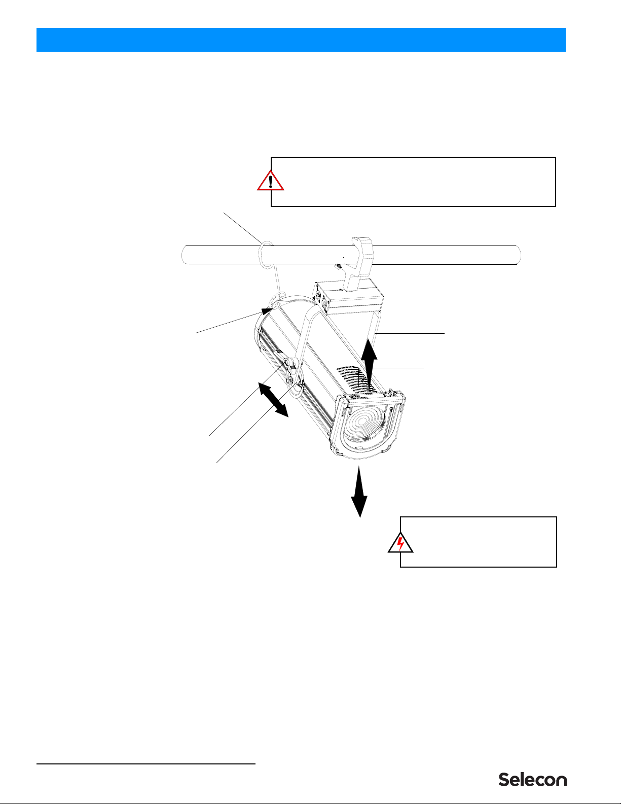
Figure 3: Luminaire Mounting
To mount on a telescopic stand, reverse the yoke under the luminaire and bolt to stand. Please note luminaire
orientation (see note in Figure 3) for proper cooling.
Note: After installing Clamp and Top Box assembly, connect luminaire cable assembly to Top Box Assembly before
mounting luminaire. Please note that the cable connector is keyed.
The supplied safety cable MUST always be used when rigging luminaires on bars, truss, etc. (as shown in Figure 4
on page 8). The supplied safety cable is recommended for all hanging installation and may be required by national
and local codes. Loop or attach safety cable to luminaire safety cable anchor point as shown and attach to structure.
You should always consult and follow all local and national codes and regulations for mounting and installation of
luminaire.
6. Pan and Tilt Adjustments
Pan Adjustment
The pan adjustment of a PLFRESNEL1 MKII LED Luminaire is achieved by loosening the yoke bolt of the securing
clamp attached to the luminaire's yoke assembly. Loosen the bolt, set the luminaire to the desired position and re-
tighten.
Yoke Assembly
Center Clamp Mounting Hole (13 mm)
Top Box Assembly
C-Clamp
Flat Washer
C-Clamp Bolt*
WARNING! *When installing a C-Clamp (or hook,
or other type of clamp) with the Top Box Assembly
as shown, you MUST use the C-Clamp Bolt
supplied with the fixture. Failure to do so may result
in damage to the Top Box Assembly or cause the
luminaire to dislodge from the clamping device.
NOTE: To allow for proper cooling, make sure
luminaire head is orientated as shown (with
forward cooling vents pointed upwards).
Top Box Assembly
Luminaire Cable
Assembly
Flat Washer
QuickStart Guide PLFRESNEL1 MKII LED Luminaire
8INSTALLATION AND SET UP
Tilt Adjustment
PLFRESNEL1 MKII LED Luminaires offer variable tilt settings. The unit can be set at a specific angle (in relation to
its mounting position) or at an angle between 0 to 90 degrees. When the yoke is in the position shown in Figure 4,
you have full range access to luminaire adjustments.
Figure 4: Luminaire Tilt Adjustment
To adjust and set tilt angle of the luminaire:
Step 1. Mount luminaire in desired location (see "Mounting" on page 6 for more information).
Step 2. Loosen, but do not remove, T-Handle Tilt Lock at base of yoke assembly as shown in Figure 4.
Step 3. Position luminaire to desired tilt position.
Step 4. Re-tighten T-Handle Tilt Lock to set position.
Yoke Assembly
Cooling Vents (see note below)
T-Handle Tilt Lock
NOTE: To allow for proper cooling,
make sure luminaire head is
orientated as shown (with forward
cooling vents pointed upwards).
Safety Cable
Sliding Yoke Assembly
Safety Cable
Anchor Point.
SAFETY CABLE: FOR LUMINAIRE, the supplied safety cable is
recommended for all hanging installation and may be required by
national and local codes. Loop/attach safety cable to safety cable anchor
point (as shown) and attach to structure.
(supplied with
luminaire)

Beam Adjustments 9
PLFRESNEL1 MKII LED Luminaire QuickStart Guide
BEAM ADJUSTMENTS
1. Beam Adjustments
To adjust the beam:
Step 1. As shown in Figure 5, loosen Beam Adjustment Knob
Step 2. Slide beam adjustment back (for spot) or forward (for flood) as desired.
Step 3. Hand-tighten Beam Adjustment Knob to lock position.
Figure 5: Beam Adjustment Knob
2. Barndoor Assembly
Selecon offers as an optional accessory, a four-leaf barndoor assembly. This assembly is sold separately and
available from your Authorized Selecon Authorized Dealer.
Spot Flood
Beam Adjustment Knob
QuickStart Guide PLFRESNEL1 MKII LED Luminaire
10 OPERATION AND PROGRAMMING
OPERATION AND PROGRAMMING
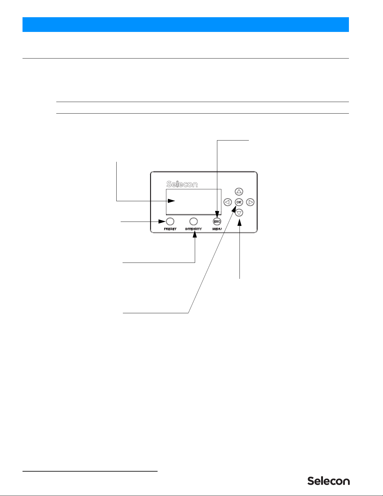
1. LCD Menu Operation
The PLFRESNEL1 MKII LED Luminaire’s LCD Display and Menu System provides local control for accessing all
the fixture’s status information, menu options, and settings.
Note: If there are multiple luminaires in a system, changes would need to be made at each LCD Menu as desired.
Upon power up, the LCD will display the main screen showing the product type/name.
Figure 6: LCD Display and Menu System
Up/Down/Left/Right Arrow Buttons -
Navigates menu system and used for
Escape Button -
Enters menu options. Navigates
OK (Enter) Button -
Accesses details, activates
a field, or enters a setting
depending on the current menu item.
selecting and setting options.
(backs up) one menu level.
PRESET Button -
Allows the recall of
LCD Display -
Displays all menu parameters and
option settings. Also displays DMX512
address (DMX models only).
INTENSITY Button -
Allows the customization of current intensity (light
output). Note, using the LEFT and RIGHT arrow
buttons you can select each RGBW channel
individually and change their intensity using the UP
and DOWN arrows.
stored presets.

LCD Menu System 11
PLFRESNEL1 MKII LED Luminaire QuickStart Guide
2. LCD Menu System
The LCD Display Menu system consists of several categories. Use the four arrow buttons as required (refer to Figure
6 on page 10) to access and make changes to the menu items. When the desired menu item is reached, press [OK] to
display the menu options. Use navigation and [OK] buttons to view status and configure the LCD Menu as required.
To navigate and access menu settings/selections:
Step 1. At Main Menu, press [ESC] / [MENU] button once. Another window will appear with sub-menu categories:
• Save a Preset
• Edit a Preset
• Color Mixer
• Settings
• Lock Fixture
• Fixture Status
• Normalize Colors
Step 2. Press [OK] at desired menu item to access and make changes.
Step 3. Make changes as desired.
Note: When DMX512 signal is present, Edit Preset and Color Mixer options will not appear in menu structure.
To navigate fixture status menus:
Step 1. At default screen, press LEFT or RIGHT arrow button once. The default menu screen will change to allow
for quick reference to the following items (note, depending on which arrow button is pressed, status screens
may appear in reverse order):
a. DMX Address (note, if fixture is UNLOCKED, hit [OK] to change DMX address).
b. Fixture Hours (displays fixture operating hours since last reset).
c. Fixture Power (displays Max Power Limit setting (in Watts), Present Power consumed by fixture (in
Watts), and Hours of Use).
d. Fixture Status (displays current operational temperature, LED status, and fan speed setting).
Step 2. Press LEFT or RIGHT arrow buttons to scroll through status screens.
Step 3. Press [ESC] at anytime to access Main Menu.
Note: When DMX512 signal is present, Edit Preset and Color Mixer options will not appear in menu structure.
3. Security
Unwanted changes to the Fixture's Configuration or Setting can be controlled by locking the fixture’s menu.
PLFRESNEL1 MKII LED Luminaires are shipped with a default numeric PIN code of "0000" (four zeros). Users
may set their own PIN code (four-digit number) via Settings > General > Set PIN. When setting a PIN code,
write it down and keep it in a secure location. Note, Selecon does not have records of PIN codes established by
users or owners.
Note: Contact Selecon technical support if a unit is locked and the PIN code is lost for instructions on how to reset
luminaire.
Note: If the Fixture is locked when it is powered down the fixture will remain in the locked state when powered up.

QuickStart Guide PLFRESNEL1 MKII LED Luminaire
12 OPERATION AND PROGRAMMING
Locking Fixture
To lock the fixture:
Step 1. At Main Menu, press [MENU] and scroll to Lock Fixture. Note, default PIN is "0000" (four zeros).
Step 2. Press [OK].
Step 3. Enter four-digit, user-selectable, PIN code. Press [OK].
Step 4. Use [LEFT ARROW] or [RIGHT ARROW] keys to highlight "YES", press [OK] or [ESC] twice to cancel
action.
Step 5. Fixture is now locked if locking process was not canceled as described in previous step.
Note: When the Fixture is Locked only the [ESC]/[MENU] key is functional. Pressing this key will display a request
a PIN code to be entered. When a valid PIN code is entered the fixture is unlocked.
4. Presets
Presets are Color Mixes that are stored in the Fixture, they can be recalled to reproduce a specific output from the
fixture. Presets are made up of a Color Mix; Red, Green, Blue, and White. They also have Intensity associated with
them.
Presets can be recalled via the User interface or by a DMX channel, when under DMX control. The Preset’s Intensity
is applied if the User Interface is used; if DMX, the DMX Intensity channel is used for Intensity.
If the fixture is locked, Presets cannot be changed at the menu.
• Locked Presets are factory Calibrated, and their Color Mix cannot be changed by the user. Their Intensity can be
changed. Three Presets (2-4), "Warm White', "Cool White", and "Day Light", are Locked.
• Preset 0, the "off" preset is also Locked to the OFF value.
•If the fixture is unlocked, User Presets can have their Color Mix and Intensity changed without restriction.
Note: If the Color Mix of a Factory Calibrated Preset is changed, by turning protection Off, an '*' is appended to the
end of the Preset's Name to indicate that the Calibrated values have been changed.
Note: DMX will take priority over any menu selected preset.
Editing Preset Names
On the Edit Preset screen, the option is available to edit the name of a preset, via Screen button. However, the names
of Presets 0, 2, 3, and 4 cannot be edited. Scratch Pad, preset 1, can be changed but retains its original functionality.
Use the [LEFT ARROW] and [RIGHT ARROW] keys to select the character to be changed and use the [UP
ARROW] and [DOWN ARROW] keys to change that character. The Character Scroll order is A-Z, space, 0-9. If you
are scrolling up the Alpha character displays as Upper Case; if you are scrolling down the Alpha character displays as
Lower Case. Stop on the character you want, ignoring case, then press the opposite [UP ARROW] or [DOWN
ARROW] key if you want to change the case. [OK] to save changes, [ESC] to cancel changes.
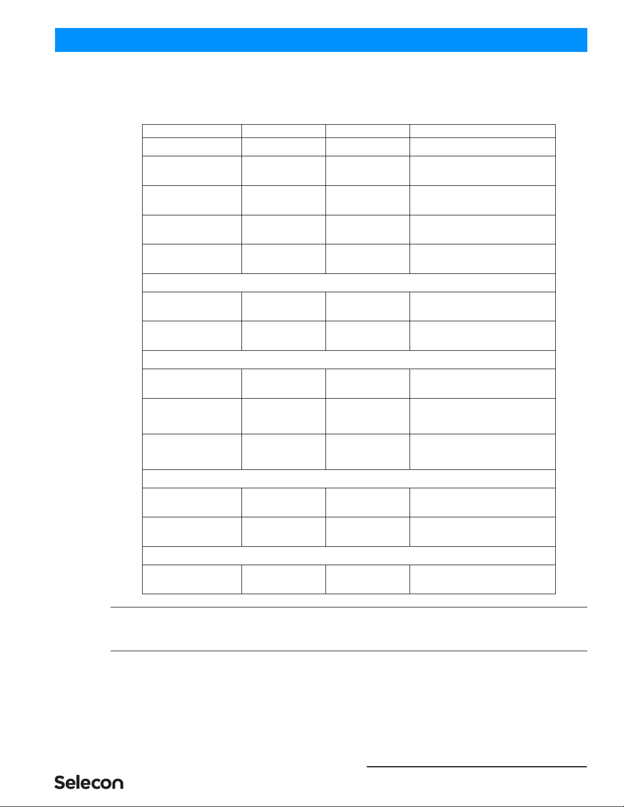
5. Settings
Table 2, “Settings Menu User-Settable Parameters,” on page 13 shows the user-settable parameters available in the
Settings menu section.
To edit a value on the Setting Screen, use the [UP ARROW] or [DOWN ARROW] keys to move the highlight to the
settings value you wish to change. Press [OK] to begin editing that value. Use the [UP ARROW], [DOWN
ARROW], [LEFT ARROW] or [RIGHT ARROW] keys to make changes to the value. Press [OK] when complete to
save changes, or [ESC] to cancel changes to that value.
Settings 13
PLFRESNEL1 MKII LED Luminaire QuickStart Guide
When done making changes on the Settings Screen press [ESC] to re-boot fixture and implement changes. Fixture
will not re-boot if nothing was changed.
Table 2: Settings Menu User-Settable Parameters
Note: To Exit the Settings screen, use the [ESC] key. [ESC] and [OK] can be used to cancel or save changes to an
individual parameter. However, once a parameter has been accepted, by pressing [OK] that change cannot be undone/
canceled by pressing the [ESC] key.
Parameter Values Default Description
General
Power, Fan
Normal Mode (120W),
Studio Mode (80W), or
Quiet Mode (60W)
Normal Mode
Sets the luminaire’s output mode - Normal
Mode (120W), Studio Mode (80W) or
Quiet Mode (60W).
Power-Up All presets Cool White
Users can set what the default preset is
when the unit is powered up. Factory
default is Cool White.
Reset Hours No, Yes No Resets luminaire’s operational hours.
Set PIN #### 0 0 0 0 (for zeros) A four-digit user-settable PIN code to lock
the fixture.
Presets
Protected No, 5 - 25 5 - 25 Determines if the factory Presets' Color
Mix is protected from changes.
Load Factory No, Yes No Reload Factory Presets, Intensity changes
will also be reloaded.
DMX
Address 001 to 512 001 DMX512 address. Note, it can be set if
displayed.
Map 8-bit, 16-bit, or 5-Chan 16-bit
Defines size/precision of DMX map. Color
Mixing/Intensity in 16-bit provides higher
resolution for precision control. 5-Chan
provides minimal channel usage.
When no DMX Off, Hold, Hold 8Hr (8
hours), or No Output Hold
If DMX is detected and then goes away,
this defines what will happen to the output.
At end of 8Hr hold Fixture goes to No
Output setting.
Display
Flip Display No, Yes No Flips (inverts) Display and Keypad Arrows.
Adj Contrast 0 - 100% 50% Use left or right arrow keys to adjust
display contrast as desired.
Fixture
Fixture ID ##### N/A Shows luminaire ID number.

QuickStart Guide PLFRESNEL1 MKII LED Luminaire
14 TROUBLESHOOTING
TROUBLESHOOTING
1. Troubleshooting Guide
The chart below provides possible causes and remedies for various error messages and/or symptoms.
WARNING! Any service and maintenance (including troubleshooting), other than described herein should be
performed by an Authorized Selecon Dealer or Service Center.
Description Symptom Possible Cause/Remedy
No light output. Fixture will not produce or
output light
Unit is set to Preset Off...
Make sure unit is set to proper Preset.
DMX command to 0 intensity...
Adjust intensity to higher level.
No power at luminaire. Luminaire does not power up
Circuit not energized...
verify circuit breaker is turned on.
Not plugged in...
ensure A/C cable is connected to power source.
Power cable wired incorrectly...
verify power cable and connector are wired correctly.
See "Connecting Power" on page 5 for more information.
DMX Data Control. Fixture will not respond to DMX
commands.
Not detecting DMX data...
Disconnect and reconnect DMX input cable.
Check all DMX connections (at control source and luminaire).
DMX data cable not wired correctly or has a broken conductor...
check DMX data cable for proper wiring.
See "Connecting to the DMX512 Network" on page 5 for more
information.
LED (light) is getting dimmer. Fixture appears not to be
operating at full brightness.
Luminaire has detected an over temperature condition...
The luminaire will reduce power to its LEDs if it senses that the
LEDs are operating over the specified temperature. LED
temperature is read and recorded through a thermistor embedded in
the LED chip.
Fan is not operating. Listen for fan operation or adjust settings to
increase fan speed. On luminaires with a display check system
status menu for status of fans and LED operation.
Local programming. Unit will not allow local
programming or changes.
Password protection is on (locked)...
Input proper password to allow local programming and/or
adjustments.
Unit is controlled by DMX...
Disconnect input cables to check issue.

AMERICAS
10911 Petal Street
Dallas, TX 75235
Tel: +1 214-647-7880
Fax: +1 214-647-8039
ASIA
Unit C, 14/F, Roxy Industry Centre
41-49 Kwai Cheong Road
Kwai Chung, Kwai Tsing
Hong Kong
Tel: +852 2796 9786
Fax: +852 2798 6546
Room 1201, Freetown Tower D
E 3rd Ring Rd S, 58
Chaoyang Qu
Beijing Shi, China
Tel: +8610-58674776
Fax: +8610-58674775
B-1-27, Dataran Cascades, No. 13A
Jalan PJU 5/1
Kota Damansara PJU 5
47810 Petaling Jaya
Selangor, Malaysia
Tel: +60 3-7611 7302
Fax: +60 3-7629 4192
EUROPE
Rondweg Zuid 85
Winterswijk 7102 JD
Netherlands
Tel: +31 543-542516
Fax: +31 543-542513
24 Sovereign Park
Coronation Road
Park Royal, London
NW10 7QP
United Kingdom
Tel: +44 020 8965 3209
OCEANIA
14H Vega Place
Rosedale
Auckland 0632
New Zealand
Tel: +64 9-481-0100
PLFRESNEL 1 LED Quick Start Guide
Document no.: 02-9701-0002
Version date: May 30 2019
© 2019 Signify Holding. All rights reserved.
All trademarks are owned by Signify Holding or their respective owners. The information pro-
vided herein is subject to change, without notice. Signify does not give any representation or
warranty as to the accuracy or completeness of the information included herein and shall not
be liable for any action in reliance thereon. The information presented in this document is not
intended as any commercial oer and does not form part of any quotation or contract, unless
otherwise agreed by Signify. Data subject to change.
Table of contents
Other Selecon Dj Equipment manuals


