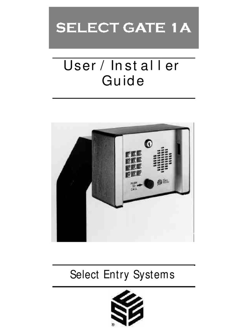
Select Engineered Systems TEC1A Series Assembly instructions

INSTALLER GUIDE
600TEC1A_INST
Jan 2020
TEC1A SERIES
Covers: T1A2LxxxBSK/DLX/PRM
T1A4LxxxBSK/DLX/PRM
Select Engineered Systems, Inc.
7991 West 26th Ave
Hialeah, FL 33016
Tel: 305 823 5410
Fax: 305 823 5215
www.selectses.com
© 2003 – 2020 All Rights Reserved

TEC1A Installer Guide
01/20
Rev B2
Page 1 of 11
1Installation –TEC1A Series Access Controllers........................................................ 3
1.1 Safety Warnings / Avertissements de Sécurité .................................................... 3
1.1.1 English Language.......................................................................................... 3
1.1.2 Sécurité Avertissements En français............................................................. 3
1.2 Coordination with Telephone Company.............................................................. 4
1.3 Mechanical Mounting .......................................................................................... 5
1.3.1 Installation Heights....................................................................................... 5
1.3.2 Surface Mount............................................................................................... 5
1.3.3 Flush Mount.................................................................................................. 5
1.3.4 Optional Weather Hood Recommendation................................................... 5
1.3.5 Sealing........................................................................................................... 5
1.4 Electrical............................................................................................................... 6
1.4.1 Grounding..................................................................................................... 6
1.4.2 Overall Main Board Layout.......................................................................... 7
1.4.3 User Connections.......................................................................................... 8
1.4.4 Option Cards............................................................................................... 10
1.5 Programming a Directory Record with a PIN into a TEC1A ............................ 11

TEC1A Installer Guide
01/20
Rev B2
Page 2 of 11
Figure 1: Installation Height for Pedestrian and Drive-Up Applications........................... 5
Figure 2: TEC1A Location of Back Box Ground Lug ....................................................... 6
Figure 3: TEC1A Ground Lug Connection ........................................................................ 7
Figure 4: Inside Door of TEC1A........................................................................................ 7
Figure 5: TEC1A User Connections................................................................................... 8

TEC1A Installer Guide
01/20
Rev B2
Page 3 of 11
1Installation –TEC1A Series Access Controllers
1.1 Safety Warnings / Avertissements de Sécurité
1.1.1 English Language
For your safety please observe the following recommendations when installing TEC1A
series product enclosures:
Never install equipment during a lightning storm or other hazardous event
Do not bring mains voltage cabling into the product enclosure or attempt to
connect mains voltage to any wires leading from the product, or the enclosure
housing itself. Only the isolating transformer supplied with the product should
be connected to the electrical mains supply by following the installation
instructions below
In wet locations, only install wiring and cabling rated for wet locations
Never touch un-insulated telephone wires or terminals unless the telephone line
has been disconnected at the telephone network interface
Follow industry-recommended installation practices when installing cables and
grounding wires
Do not attempt to use the provided isolating transformer to supply other
equipment - it is intended solely for the purpose of powering access controllers
in the TEC1A series
1.1.2 Sécurité Avertissements En français
Pour votre sécurité, observez les recommandations suivantes lors de l'installation des
boîtiers pour le produit de la série TEC1A :
N'installez jamais l'équipement pendant un orage ou tout autre événement
dangereux
Ne connectez aucun câblage de courant du secteur au boîtier du produit. Ne tentez
pas de connecter le courant du secteur aux fils sortant du produit ou au boîtier lui-
même. Ne connectez au courant du secteur que le transformateur de séparation
fourni avec le produit, en suivant les instructions d'installation ci-dessous
Dans les emplacements mouillés, installez uniquement des fils et câbles
homologués pour les emplacements mouillés
Ne touchez jamais des fils ou des bornes de téléphone non isolés, sauf si la ligne
téléphonique a été déconnectée au niveau de l'interface réseau téléphonique
Suivez les pratiques d'installation recommandée par l'industrie lors de
l'installation des câbles et des fils de mise à la terre
Ne tentez pas d'utiliser le transformateur de séparation à l'alimentation électrique
d'autres équipements. Il est destiné uniquement à l'alimentation électrique des
contrôleurs d'accès de la série TEC1A

TEC1A Installer Guide
01/20
Rev B2
Page 4 of 11
1.2 Coordination with Telephone Company
Installation of TEC1A requires coordination with your telephone company.
A Touch-Tone™ line is required for dialing out purposes –legacy pulse dialing is not
available.
The phone company may require the following information:
The ringer equivalence number (see label inside TEC1A enclosure).
The FCC registration number (see label inside TEC1A enclosure).
The desired location of the telephone jack (must be given to the phone company
at the time the phone line is ordered).

TEC1A Installer Guide
01/20
Rev B2
Page 5 of 11
1.3 Mechanical Mounting
1.3.1 Installation Heights
Figure 1 shows the recommended installation heights for TEC1A series access
controllers.
Figure 1: Installation Height for Pedestrian and Drive-Up Applications
1.3.2 Surface Mount
Mount the back-box using the holes provided.
1.3.3 Flush Mount
Cut a hole the size of the back box 8 ½" (w) x 11 ¾" (h) in the wall, then mount the
TEC1A in the hole.
1.3.4 Optional Weather Hood Recommendation
It is recommended that an optional weather hood be used when mounting a TEC1A in a
stand-alone application to protect it from direct exposure to rain and snow. Please call
Factory for availability.
1.3.5 Sealing
All openings and penetrations of the TEC1A enclosure should be sealed with suitable
RTV silicon sealant.

TEC1A Installer Guide
01/20
Rev B2
Page 6 of 11
1.4 Electrical
1.4.1 Grounding
The TEC1A MUST BE AT EARTH GROUND POTENTIAL.
Connect a #16 stranded or larger wire from the ground lug in the base of the back box of
the TEC1A to a cold water pipe or other suitable ground. This wire should be less than
50 feet in length. See Figure 2 for the location of the back box ground lug.
Back Box Ground
Lug
Figure 2: TEC1A Location of Back Box Ground Lug

TEC1A Installer Guide
01/20
Rev B2
Page 7 of 11
Figure 3: TEC1A Ground Lug Connection
1.4.2 Overall Main Board Layout
See Figure 4 below for an image of the main board.
Comm Board
Mounting Location
(Add-on option)
MUI Board Mounting
Location
(Add-on option)
2-Reader Board
Location
(Add-on option)
User Connection Strip
P1A (Connector Plug
shown)
User Connection Strip
P1 (Connector Plug
shown)
Postal Lock Switch
Door Ground Stud
Figure 4: Inside Door of TEC1A

TEC1A Installer Guide
01/20
Rev B2
Page 8 of 11
1.4.3 User Connections
Figure 5 shows the Terminal Strip connections P1 and P1A for user connections, along
with the Door Ground Stud. No other connections are required.
Figure 5: TEC1A User Connections
1.4.3.1 Telephone Connection
Use the RJ-11 supplied with the flying lead to connect the TEC1A to the telephone
network provided.
WARNING –FCC Regulations
Failure to use the RJ-11 supplied may invalidate FCC regulatory compliance.
CAUTION Do Not Connect Other Non-SES Equipment
NO OTHER TELEPHONE DEVICES or NON-SES EQUIPMENT should be attached to this
phone line.

TEC1A Installer Guide
01/20
Rev B2
Page 9 of 11
The exception is when connecting additional SES access controllers. In this case, an
optional MUI plug-in board must be used, allowing up to four SES Access Controllers
to be connected on the same line.
1.4.3.2 TEC1A Power
Power can be supplied in ONE of two ways. Either:
1. Using the SES-supplied 16.5 20 VA transformer OR
2. Connecting an external 12v DC source
WARNING
Do not use both connections at the same time. Damage to the TEC1A may occur and
void the warranty.
The SES transformer wires should be connected into the terminal pair “AC” and “AC” on
connector P1. Plug the transformer into a standard 110v ac mains socket.
If used instead, the external battery should be connected into the terminals “+12” and
“COM” on connector P1 with NO connections on “AC” and “AC”. Do not use “COM”
associated with either the REX inputs or Relays to supply battery power.
For an external 12V DC source, idle current consumption is as follows:
12V DC IDLE Current Table
LCD
Display
Idle Current (mA) Per Model
Basic
Deluxe
Premium
2-Line
55
79
139
4-Line
82.5
106.5
166.5

TEC1A Installer Guide
01/20
Rev B2
Page 10 of 11
1.4.3.3 Rex (Request to Exit) Inputs
The request to exit inputs (RX1 and RX2) are VOLT-FREE (dry) contacts located on
connector P1 as shown in Figure 5. No external voltage is either required or desired.
To use either Rex input, connect the COM (between RX1 and RX2 of connector P1) to
one side of the external relay’s contact being used to request exit, then connect either
RX1 or RX2 to the other side of the relay contact as desired. Figure 5 refers.
WARNING –Rex Inputs
Connecting an external voltage source to either Rex input will cause damage and
void the warranty.
1.4.3.4 Relays
Relays are connected to terminals on connector P1A. Both normally open (NO) and
normally closed (NC) contacts are available for both relays without the need for board
configuration.
WARNING –Relay Contacts Maximum Ratings are 2A @ 24 Volts AC or DC
Failure to comply with the maximum ratings shown for relays will cause damage
and void the warranty.
1.4.4 Option Cards
Three separate option cards can be added to the TEC1A:
Multiple Unit Interface (MUI) Card
Comm Board
2-Reader Board
The instructions for installation of each of these can be found on the SES website
www.selectses.com or with the individual card packages when ordered.

TEC1A Installer Guide
01/20
Rev B2
Page 11 of 11
1.5 Programming a Directory Record with a PIN into a TEC1A
The following steps show how to set a directory record (Code, Name, Phone # and PIN
for entrance 1 with 24/7 access) using the keypad. It assumes the TEC1A is powered on
and that the Welcome Page e.g. “Press # to View Directory” is displayed before starting.
Note that Steps 4 and 5 are included to check if PINs are enabled. Once PINs are enabled,
steps 4 and 5 can be skipped for future entries. For all other settings please refer to
“TEC1A Series Menus”.
Steps to Program a Directory Record with a PIN into a TEC1A using the Keypad
#
Step Description
Keypad Action
Resulting Display
1
Enter Programming
Mode
Press * and 0 at same time
PASSWORD
2
Enter Password
Press 6 digit password (default is
“777777”) then *
MAIN MENU 1 - 8
3
Select Codes & Names
Press 1
CODES & NAMES
SELECT 1 - 9
4
Skip this step if you know
PINs are enabled
Press 8
ENABLE PINS = 0 or
ENABLE PINS = 1
5
Complete check of
Enable PINs setting
If ENABLE PINS = 0, press 1 then *
If ENABLE PINS = 1, press *
CODES & NAMES
SELECT 1 - 9
6
Select Add New
Press 1
CODE =
7
Enter a code e.g. 100
Press “100” then *
NAME =
8
Enter a name e.g. JOHN.
Note: #moves cursor to next
character
Press J# O# H# N# then *
PHONE # =
9
Enter phone number
e.g. 3055551212 then *
PIN =
10
Enter 4-digit PIN
e.g. 1234 then *
ENTRANCE = 0
11
Set Entrance 1
Press 1 then *
TG GROUP = 0
12
Set Group 0 (24/7 access)
Press 0 then *
CODE =
13
Enter more records
OR
Repeat as needed from end of step 6
with new data.
Note that no two codes and no two
pins can be identical.
14
Exit Programming Mode
Press *0 together
Welcome Page
This manual suits for next models
6
Table of contents
Other Select Engineered Systems IP Access Controllers manuals
