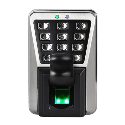
NESS ID TECK Finger007 User manual

IDTeck
Finger007
Access Controller
Rev. V4.0
USER’S MANUAL
The specification contained in this manual are subject to change without notice at any time.

101-092 2 FINGER007 – Version 4.0
IDTeck
–
FINGER007 FINGERPRINT & PROXIMITY READER
TableofContents
1. IMPORTANT SAFETY INSTRUCTIONS
2. INTRODUCTION
2.1 IDENTIFYING SUPPLIED PARTS
2.2 ABOUT NESS - IDTECK FINGER007
2.3 SPECIFICATION
3. PRODUCT OVERVIEW
3.1 FUNCTIONS
3.2 PRODUCT EXPLANATION
3.2.1 PANEL DESCRPTION
3.2.2 COLOR CODED & WIRING TABLE
4. INSTALLATION TIPS & CHECK POINT
4.1 CHECK POINTS BEFORE INSTALLATION
4.1.1 CABLE/WIRE
4.1.2 TIPS FOR PLACING DEVICES
4.2 CHECK POINTS DURING INSTALLATION
4.2.1 TERMINATING RESISTANCE
4.2.2 DISCCORD OF ELECTRIC POTENTIAL
4.2.3 EARTH GROUND
4.3 TIPS TO MAXIMIZE READ RANGE OF RFID READERS
4.3.1 POWER SUPPLY
4.3.2 ENVIRONMENTAL SOURCES OF ELECTRICAL
INTERFERENCE.
5. INSTALLATION
5.1 TEMPLATE (Wall Mount)
5.2 BACKUP BATTERY S/W
5.4 SYSTEM INITIALIZATION (Extra Reader Port)
5.4 WIRING
5.4.1 POWER
5.4.2 INPUT CONNECTIONS
5.4.3 OUTPUT CONNECTIONS
5.4.4 READER CONNECTIONS (Extra Reader)

101-092 3 FINGER007 – Version 4.0
IDTeck
–
FINGER007 FINGERPRINT & PROXIMITY READER
6. COMMUNICATIONS
6.1 RS232 COMMUNICATION PORT CONNECTION
6.2 RS-422 COMMUNICATION PORT CONNECTION
6.2.1 RS-422 COMMUNICATION (STANDALONE)
6.2.2 RS-422 COMMNUNICATION
(MULTIPLEFINGER007 CONNECTIONS)
6.3 DIAL UP MODEM
6.4 TCP/IP CONVERTER (EXTERNAL VERSION)
7. BASIC SETTINGS
7.1 INITIALIZATION OF FINGER007
7.2 HOW TO ENTER THE SETUP MENU
7.3 DATE AND TIME SETTING
7.4 ID REGISTRATION
8. OPERATION
8.1 NORMAL OPERATION
8.2 DEFAULT SETTING
9. SETTING CHANGES
9.1 SETUP MENU F1
9.2 SETUP MENU F2
9.3 SETUP MENU F3
9.4 SETUP MENU F4
APPENDIX
A. THE RELATION BETWEEN INPUT AND OUTPUT (DEFAULT)
B. TROUBLE SHOOTING
FCC REGISTRATION INFORMATION
CONTACTS
TEMPLATE

101-092 4 FINGER007 – Version 4.0
IDTeck
–
FINGER007 FINGERPRINT & PROXIMITY READER
1. IMPORTANT SAFETY INSTRUCTIONS
To prevent injuries to persons and damages to property, please read all the instructions and follow them
whenever you deal with this product.
After reading, please put this instruction manual where it can be easily seen for the system operator.
ON INSTALLATION AND POWER
Use 12V DC power ONLY.
- Connecting to higher than 12V DC may result in a risk of electric shock, fire, or heavy damage of the unit.
Do NOT install this product at places with wet or metallic dust, or that can be watered.
- There may be risks of electric shock and fire.
Do NOT install this product near electric motors running.
- The unit may not operate normally.
Do NOT set this product near heaters or any thing that produces heat.
- There may be a risk of fire.
Be ALWAYS careful not to short-circuit any part of the circuitry with tools like a screwdriver in hand.
- There may be a risk of fire or heavy damage of the unit.
ON MAINTENANCE
Do NOT use any kind of liquid for cleaning.
- There may be a risk of electric shock, fire or heavy damage of the unit. Use an air spray, if needed.
Users are cautioned NOT to attempt repair of this product or modify the wirings set by the installer at there
own discretion.
- It may pose the risk of fire, hardware damages, or abnormal operations of the unit.
It is recommended not to use a flammable spray or something easy to burn near this product.
- There may be the risk of an explosion or fire.
Keep the unit away from any unauthorized people.
- It may cause abnormal operations of the unit.

101-092 5 FINGER007 – Version 4.0
IDTeck
–
FINGER007 FINGERPRINT & PROXIMITY READER
2. INTRODUCTION
2.1 IDENTIFYING SUPPLIED PARTS
Please unpack and check the contents of the box. (Optional accessories, if purchased, may be included in
the package)
2.2 ABOUT NESS - IDTECK FINGER007
The NESS - IDTECK FINGER007 is a highly advanced, intelligent single door controller (network
able) with a powerful 32bit and dual 8bit microprocessor to meet the market requirement for a robust
integrated solution for access control and time & attendance. The unit is designed to be flexible and
reliable as well as provide the ultimate in biometric high security at a reasonable cost. This user-friendly
device allows you to register up to 720 fingerprint IDs (optional 2,000/4,500); add / delete user IDs
conveniently; store up to 26,000 transactions in its event buffer; easily report and archive information to
Excel or Access databases; and ultimately successfully manage all access control and time & attendance
issues. With a built-in 4" RF reader, keypad for Personal Identification Numbers (PIN), and a
sophisticated biometric fingerprint analyser, the FINGER007 offers up to three levels of ID verification.
Any combination of proximity (RFID), PIN, and biometric may be used and different verification levels
can be custom programmed for each user or user group. Four independent inputs can be utilized for a
wide variety of controls including exit buttons, door contacts, PIR sensors and fire detection equipment.
Actions to be taken and time settings can be programmed with the front keypad or via the intuitive
Windows based software program. The FINGER007 can be used both as a stand-alone system and also
be networked. All control setting values such as ID numbers, inputs/outputs, real-time clock, time
schedules, and event transaction reports can be uploaded and/or downloaded to and from the host
computer. The compact and contemporary unit is easily installed and programming requires no significant
knowledge of access control or time & attendance. The Three-LED indicator lights inform you of the
systems operating status at real time and the digital display acts as a programming aid as well as a
regulation time clock. By bundling the ultimate in high security access control and comprehensive
employee management tools into a compact user friendly unit, the field proven NESS - IDTECK
FINGER007 has made real what until recently was thought only to be possible in science fiction.

101-092 6 FINGER007 – Version 4.0
IDTeck
–
FINGER007 FINGERPRINT & PROXIMITY READER
2.3 SPECIFICATION
CPU 32bit, dual 8bit Microprocessor
Memory Program Memory : 64KB EEPROM
Data Memory : 512KB SRAM(battery backup)
Power DC 12V/ 350mA max.(excluding lock current)
Card Holders/
EventBuffer
Card Holders : 720(optional 2,000/4,500)
Event Buffer : 26,000
Reader Port 1 Extra port, 1 Internal port
Reader Data Format
Standard 26bit Wiegand (NESS - IDTECK FINGER007)
Standard 34bit Wiegand (NESS - IDTECK
FINGER007SR)
8 bit burst Format for keypad reader
Communication port RS232/RS422 (up to 32 channels) selectable 4800, 9600
(Default), 19200, 38400bps communication speed
Input/Output
4 Input ports/ DC12V/ 20mA
2 Relay Output ports/ DC12V/ FORM-C Relay 2A max.
2 TTL Output ports: DC5V/ 20mA
Keypad 16 Keypad (Back lighting)
LCD 1 x LCD module, 2Lines x 16ch, 65.6 x 13.8mm view
area
Light source LED (finger unit)
Mounting Wall mounted
Colour Dark pearl grey
Material Polycarbonate
Self diagnostic Yes
Reset Power on Reset and Watchdog timer reset
Operation Status 3 LED (red, green, yellow) indicators
Operation
Environment 0°C ~ +40°C, 10% ~ 90%(Humidity)
Weight 525g
Dimensions 161.6mm x 122.6mm x 36.5mm
Certification FCC Class A part 15, UL294, MIC

101-092 7 FINGER007 – Version 4.0
IDTeck
–
FINGER007 FINGERPRINT & PROXIMITY READER
3. PRODUCT OVERVIEW
3.1 FUNCTIONS
Stand-Alone Operation
The NESS - IDTECK FINGER007 (& FINGER007SR) is capable of having two readers (entry
(built in) and exit). The unit receives card data signals from the RF readers and determines whether or
not to unlock the door. When an input signal is sent, for example from and activated sensor or if the
exit button pressed, the controller generates and logs an appropriate response. All events are kept in its
own memory and sent to the host computer. The access controller is a true standalone device that in
the event of a malfunction will not affect other units, even if used in conjunction with one another.
Operation with Host Computer
All event transactions can be managed via the host computer. The data transmitted from the controller
can be displayed and stored on the host PC.
Data Backup
The controller retains all user information and event data for 30 days, even in the event of power
failure. CAUTION : Battery S/W must be set correctly before the unit running.
(See the INSTALLATION section)
Keypad
If the NESS - IDTECK FINGER007 is not connected to host PC, the integrated keypad and LCD
display module can also be used for the entire programming process manually.
Anti-Pass-Back
Using an additional proximity reader foe exiting, the Anti-Pass-Back mode can be set. Anti-Pass-Back
mode prevents any entry or exit when the registered user did not properly followed one entry and one
exit by the Anti-Pass-Back rule. APB only allowed exit for the user once got into the door first and it
doesn’t allow any user trying twice entry or twice exit
Input/Output
The NESS - IDTECK FINGER007 has built-in 4 inputs and 4 outputs (2 relay outputs and 2 TTL
outputs) which can be used to manipulate a wide variety of controls.

101-092 8 FINGER007 – Version 4.0
IDTeck
–
FINGER007 FINGERPRINT & PROXIMITY READER
Time Schedule Set-up
You can program 10 time schedules and apply one time schedule to each user. Each time schedule has
8 different time zones from Monday to Sunday (7 time zones) and one holiday. Each time code has 5
different time intervals so you can program 5 different time intervals to each day. Also you can
program time schedule for individual inputs and outputs.
Note each input (or output) can have a time schedule assigned to it. In this case the input will only be
active during this time schedule and the output can also active automatically during a time schedule.
Each time schedule is also linked to one of the holiday schedules.
Holiday Schedule Set-up
Excepting Sunday, you can program 32 holidays to one holiday schedule. Each holiday schedule is
linked to one time schedule, which has assigned time codes for holidays. So you can program all
holidays to holiday schedule and the time code for holidays is programmed to holiday time zone of
time schedule.
Example : A : Holiday schedule 01 linked to time schedule 01,
Holiday schedule 02 linked to time schedule 02.
B : Holiday schedule 02 linked to time schedule 01,
Holiday schedule 01 linked to time schedule 02.
Forced Door Open and Door Open Too Long Alarm
When a door is opened by force, the Door Contact Output is generated. And, when the door is opened
by normal operation and not closed after 20 sec. A door-open alarm (blink buzzer) will be generated
until the door is closed.
Duress Alarm / Alarm Arm – Disarm Code
You can select Duress Mode / External Alarm Arm - Disarm feature to be enabled or disable. If you
select Duress Mode enable, in case of Duress, enter the 2 digit Duress Password (code) and press
<ENT> and open the door as normal. Both the door contact and alarm outputs will activate and the
Duress alarm event will be sent to the host PC.
If you wish to use this feature to Arm / Disarm an alarm system (eg Ness D8/16 or D24 Alarm system),
enter the 2 digit Arm / Disarm Password (code) and press <ENT>. In this case the door will unlock as
normal via the door contact and the “Aux” output can be used to pulse the Keyswitch / Arm-Disarm
input of the alarm panel. (The Arming / Disarming event can also be sent to the host PC.

101-092 9 FINGER007 – Version 4.0
IDTeck
–
FINGER007 FINGERPRINT & PROXIMITY READER
1:N Certification (IDENTIFICATION)
You can certify using the fingerprint alone without RF card or PIN. You can set this function through
the <TYPE SELECTION> in SETUP MENU F1. In the IDENTIFICATION MODE, the security level
gets higher automatically, FRR(False Rejection Ratio) as well, but FAR(False Accept Ratio) gets
lower, which may result in a lower recognition ratio. When using this mode, you have to press the
<ENT> key first, then the fingerprint scanner waits for a fingerprint to be scanned. When a
fingerprint-scanning is completed, FINGER007 compares the data and makes corresponding outputs.
zFINGER007(of V4.75 or higher) has a sensor(finger detect).So in identification mode, you need
not enter <ENT> key. If you touch at finger sensor, then Finger007 detects your finger and
scanning automatically.
zCAUTION : The number of registrants must be 50 or less.
3.2 PRODUCT EXPLANATION
3.2.1 PANEL DESCRIPTION
Fingerprint
Input window
LCD
3 LED (showing
system status)
Function Key
16 Numeric keypad

101-092 10 FINGER007 – Version 4.0
IDTeck
–
FINGER007 FINGERPRINT & PROXIMITY READER
•FINGER007(of V4.70 or higher) has a S/W(reverse side – Template hole) for the backup battery
connection. Before the FINGER007 installation, it needs to be connected before H/W initialize so that
backup battery can retain the memory during power failure.
3.2.2 COLOUR CODED & WIRING TABLE
IO PORT NAME SIGNAL NAME COLOUR CODED
POWER
Main Power(+12V) +12V RED
Power Ground GND BLACK
OUTPUT
Door Relay(COM) COM(1) Grey with Red stripe
Door Relay(NC) NC(1) Blue with White stripe
Door Relay(NO) NO(1) White with Red stripe
Alarm Relay(COM) COM(2) White
Alarm Relay(NC) NC(2) Purple with White stripe
Alarm Relay(NO) NO(2) Purple
TTL Output1 TTL1 Orange with White stripe
TTL Output2 TTL2 Brown with White stripe
INPUT
Exit Button EXIT Orange
Door Sensor CONTACT Yellow with Red stripe
Aux Input 1 IN1 Green

101-092 11 FINGER007 – Version 4.0
IDTeck
–
FINGER007 FINGERPRINT & PROXIMITY READER
Aux Input 2 IN2 Green with White stripe
EXTRA READER
Wiegand Data0 DATA0 Pink
Wiegand Data1 DATA1 Cyan
RS232 INTERFACE
RS232-TX TXD Black with White stripe
RS232-RX RXD Red with White stripe
RS422 INTERFACE
RS422-TX(-) TX(-) Yellow
RS422-TX(+) TX(+) Grey
RS422-RX(-) RX(-) Blue
RS422-RX(+) RX(+) Brown
4. INSTALLATION TIPS & CHECK POINT
Installing the FINGER007 is a relatively easy task. It can be installed with common hand tools and readily
available communications wire. This section provides information about wiring, wire runs and other information
to make the installation quick and easy.
4.1 CHECK POINTS BEFORE INSTALLATION
4.1.1 CABLE / WIRE
Good electrical connections will minimize the line losses and avoid damages to the FINGER007 control
electronics. Use good quality and proper thickness of wire with durable insulation such as vinyl or PVC. It
may be faster and much economical to run multiple, twisted pair cable rather than individual pairs. The
following cable and wire thickness from the Belden Master Catalog 885 are adequate for the most
FINGER007 applications. These are offered as a reference only.
Belden No. 9745 3 twisted pairs, 22 AWG, 7/30 stranded, unshielded, PVC insulation and jacket,
14.7 ohms/1000 feet (about 300meter).
Belden No. 9750 3 twisted pairs, 20 AWG, 10/30 stranded, unshielded, PVC insulation and jacket,
10.3 ohms/1000 feet (about 300meter).
Belden No. 8303 3 twisted pairs, 22 AWG, 7/30 stranded, shielded, overall foil/braid shield, PVC
insulation and jacket, 14.7 ohms/1000 feet (about 300meter).
zCONDUIT
The FINGER007 does not normally require conduit. However, some location may require conduit for
wire protection. Check installation requirements and specifications for your site.
zCOMMUNICATIONS WIRING
FINGER007 communication is required for using twisted pair wires.
CAUTION : Distance can be reduced by surroundings.
Cable Range between Host & Finger007

101-092 12 FINGER007 – Version 4.0
IDTeck
–
FINGER007 FINGERPRINT & PROXIMITY READER
Cable Standard RS-232C RS-422 Standard
1.25mm 15m 1,200m UL
0.75mm 15m 1,000m UL
0.3mm 15m 700m UL
Cable Range between Finger007(of V4.70 or higher) & Proximity Reader
Cable Standard WIEGAND
DATA POWER LINE Standard
1.25mm 150m 90m UL
0.75mm 150m 60m UL
0.3mm 100m 30m UL
zPOWER WIRING
Wires supplying power to FINGER007 may be either twisted or non-twisted pairs. Select the proper
wire size to minimize line losses.
zOTHER WIRING
Other wiring not mentioned above may be twisted or non-twisted pair wires. This would include wires
to door contact sensors, door lock devices and other auxiliary devices. Wire runs should dictate the
wire size used.
Cable Range between Finger007 & Lock, Finger007 & Alarm device
Cable Standard LOCK ALARM Standard
1.25mm 90m 90m UL
0.75mm 60m 60m UL
0.3mm 30m 30m UL
CAUTION : Install a surge absorber or reverse surge protector(diode) at any relay contact that
switches DC voltages to an inductive load.
4.1.2 TIPS FOR PLACING DEVICES
zFINGER007 & EXIT READER (CARD READER)
- Select a site to be found easily by users.
- Prevent it from external heat.
- Select a place safe from dirt.
- Protect if from water or dampness.
- Attach the unit to a plane & solid place in order it to be held strong.
- Keep the unit in distance of more than 10Cm from any metal material, monitor, motor, current
transformer and others, otherwise they may affect to the read range of the unit.
zDOOR HINGE
- Metal door (Electric Lock) : Protect lock line between door and lock applying door hinge or door
cord.
- Glass door : Generally, door hinge is not used but use bracket(cover) on the bottom of the door for
door cord.

101-092 13 FINGER007 – Version 4.0
IDTeck
–
FINGER007 FINGERPRINT & PROXIMITY READER
zDOOR LOCK
Metal door
- Choose door type : Electric striker or EM lock depending on the direction of door open.
. Out direction open door – EM type is recommend.
. In direction open door – Electric type is recommend.
Glass door
- Use deadbolt type
. In case of door frame on the upper side of the door, make lock hole on the door frame before
install the door frame.
. In case of door frame on the bottom side of the door, use lock bracket and door cord.
. Place hinge on the very center of the door and then make lock hole.
4.2 CHECK POINTS DURING INSTALLATION
4.2.1 TERMINATING RESISTANCE
If you use RS422/RS485 communication method, put terminating resistance in order to decrease noise
of the communication cable.
It helps data communication when there is noise.
100 ~ 120Ωmay be used.
Connect the resistance the first and last device connected in the line
CAUTION : In case that use terminating resistance, signal level as well as noise is decreased too.
Use properly fit in communication environment
4.2.2 DISACCORD OF ELECTRIC POTENTIAL
zSymptoms Seen In Case AC Input Electric Potential Disaccord
Communication shut down within controllers.
Error of controller operation.
To prevent it from the disaccord of electric potential, use a same power source for all the
controllers.
zSymptoms Seen In Case DC Input Electric Potential Disaccord
The data read in reader and sent to controller gets damaged.
In order to prevent from the disaccord of electric potential of the DC inputs, use same power
source or use common GND(-).

101-092 14 FINGER007 – Version 4.0
IDTeck
–
FINGER007 FINGERPRINT & PROXIMITY READER
4.2.3 EARTH GROUND
The FINGER007 must be properly grounded to the earth for safety reasons and to prevent damage to
the micro-electronics due to electrostatic discharges. The FINGER007 must be connected to earth
ground either through conduit, if used, or through a separate ground wire.
On-site connection to earth ground can be accomplished through :
A earth ground rod, A metal water pipe, The building’s structural steel, A ground grid
zHow To Ground
Make connection with grounding bar or pipe of the building.
Connect shield of data and communication cable.
Grounding must be done one direction only otherwise it reverse to device giving fatal damage to
the device.
The grounding for communication cable, it must be less than 10Ω.
4.3 TIPS TO MAXIMIZE READ RANGE OF RFID READERS
4.3.1 POWER SUPPLY
zUse linear, series pass power supplies. Switching power supplies may reduce the read range.
zUse a separate dedicated power supply for each reader. Do not use the reader’s power supply for other
equipment, particularly when operating switched inductive loads such as motor control relays and
solenoids.(i.e. magnetic locks, latch or strike)
4.3.2 ENVIRONMENTAL SOURCES OF ELECTRICAL INTERFERENCE
zMetal affects radio signals. Do not cover the face of the reader with metal any kind.
zReduce or eliminate unwanted signals from external sources.
zDo not place the reader wiring bundled in conduit with AC power cable, lock power, or signal wiring.
zMaintain all reader wiring a minimum distance of 12"(30Cm) away from other wiring such as AC
power, computer data wiring, telephone wiring, or wiring to electric locking device, etc.

101-092 15 FINGER007 – Version 4.0
IDTeck
–
FINGER007 FINGERPRINT & PROXIMITY READER
zDo not install the reader in areas where sources of broad spectrum EMI noise may be present
examples of EMI broad spectrum noise producers are motors, pumps, generators, AC-DC converters,
uninterruptible power supplies, AC switching replays, light dimmers, computer monitors and CRTs.
5. INSTALLATION
5.1 TEMPLATE
•Tear off last page and use provided template to drill two 6-32 holes and one ½” hole on the proper location of
the wall to mount the Wall Mount bracket as shown below.
(If the gang box is already installed on the wall then skip this step.)
•Using 2 screws, install wall mount to the wall.
* CAUTIONS *
Before mounting the NESS - IDTECK FINGER007 unit to the Wall Mount bracket, an operational test of
the unit should be completed, because the locking pins will lock the unit to the Wall Mount. Removing the
unit from the Wall Mount bracket after it has been snapped in place may cause damage to the bracket and
prevent reattachment.
•Insert 5 O-Rings to the Wall Mount as indicated, then run the cable from the main unit through the center
hole and snap in place the main unit to Wall Mount. Make sure that the main unit is securely locked in place
with Wall Mount.

101-092 16 FINGER007 – Version 4.0
IDTeck
–
FINGER007 FINGERPRINT & PROXIMITY READER
5.2 BACKUP BATTERY S/W
FINGER007(of V4.70 or higher) has a S/W(reverse side – Template hole) for the backup battery
connection, which is left open circuit to prevent any current consumption of backup battery(Figure : S/W
setting). Before the FINGER007 installation, it needs to be connected so that backup battery can retain
the memory during power failure.
Figure : S/W SETTING Figure : S/W location
5.3 SYSTEM INITIALIZATION (Extra Reader Port)
You must operate H/W initialization, before the FINGER007 installation.
Of V4.70 or higher, you must connect battery backup S/W in reverse side before H/W initialization.
You can H/W initialize using extra reader port. First, turn off the system power and connect 3 wires (pink,
cyan and black(GND)), and turn on the system power. Then you can hear “Initialize beep” and display ①
picture.
System
○
3
System is Clear
○
4
Master Password
[ _ _ _ _ ]
○
2
System Initialize
1 – Yes, 0 - No
○
1
1. ①: If you want H/W initializing, enter key <1>.
2. ②: Enter initial master password(<3141>).
3. ③: Showing initializing.
4. ④: After initializing – Main power OFF and separate 3 wire and main power ON again.

101-092 17 FINGER007 – Version 4.0
IDTeck
–
FINGER007 FINGERPRINT & PROXIMITY READER
5.4 WIRING
5.4.1 POWER
- Connect (+) wire of DC 12V power to +12V(Red wire) terminal.
- Connect GND(-) wire of DC 12V power to GND(Black wire) terminal.
5.4.2 INPUT CONNECTIONS
Exit Button Connection (EXIT)
- Connect one wire from an Exit Button to EXIT(Orange wire).
- Connect the other wire from the Exit Button to the GND(Black wire).
Door Contact Sensor Connection (CONTACT)
- Connect one wire from a Door Contact Sensor to CONTACT(Yellow with Red stripe).
- Connect the other wire from the Door Contact Sensor to GND(Black wire).
Auxiliary Input Connection (Applied IN1, IN2)
- Connect one wire from an Auxiliary Input Device to one of the IN1(Green wire), IN2(Green with White
stripe).
- Connect the other wire from the Auxiliary Input Device to GND(Black wire).
Figure : INPUT DEVICES CONNECTION
5.4.3 OUTPUT CONNECTIONS
Door Lock (Power Fail Safe) Connection (Relay 1)
- Connect COM port of Relay 1 to + 12V.
- Connect NC port of Relay 1 to (+)wire of door lock device.
- Connect GND port to (-)wire of door lock devices.
Door Lock (Power Fail Secure) Connection (Relay 1)
- Connect COM port of Relay 1 to + 12V.
- Connect NO port of Relay 1 to (+)wire of door lock device
- Connect GND port to (-)wire of door lock devices
Alarm Device Connection (Relay 2)
- Connect COM port of Relay 2 to + 12V.
- Connect NO port of Relay 2 to (+)wire of Alarm devices.
- Connect GND port to (-)wire of Alarm devices

101-092 18 FINGER007 – Version 4.0
IDTeck
–
FINGER007 FINGERPRINT & PROXIMITY READER
Figure:DOORLOCK,ALARMDEVICECONNECTIOIN
CAUTION : Please add one DIODE as shown above.
DIODE : Fast recovery DIODE(current : Min. 1A), 1N4001 ~ 1N4007 or similar
5.4.4 READER CONNECTIONS(Extra Reader)
Proximity Reader Connection
- Connect (+)wire of the Proximity Reader to +12V(Red wire)
- Connect (-)wire of the Proximity Reader to GND(Black wire)
- Connect Data-0 wire of the Proximity Reader to DATA0(Pink wire)
- Connect DATA-1 wire of the Proximity Reader to DATA1(Cyan wire)
•Compatible Readers(Extra Reader) :
FINGER007/iPFINGER007: Standard 26bit Wiegand Format Proximity Readers
Standard 26bit Wiegand + 8bit Burst Format Proximity and keypad Reader
FINGER007SR : Standard 34bit Wiegand Format Proximity Reader
Standard 34bit Wiegand + 8bit Burst Format Proximity and keypad Reader
•Recommended Readers :
FINGER007 : RF-TINY, RF10/20/30/70/500, RFK101, FGR006, FGR006EX
iPFINGER007: iP10/20/30, iPK101
FINGER007SR : SR10/20/30, SRK101, FGR006SRB
Figure:READERCONNECTION

101-092 19 FINGER007 – Version 4.0
IDTeck
–
FINGER007 FINGERPRINT & PROXIMITY READER
6. COMMUNICATIONS
6.1 RS232 COMMUNICATION PORT CONNECTION
A 9-pin connector (Serial communication connector, female) is required to connect the FINGER007 to a
host computer via RS232 communication Please follow the instructions.
- Connect RS232-TX port of FINGER007 to the pin 2 of the 9-pin connector.
- Connect RS232-RX port of FINGER007 to the pin 3 of the 9-pin connector.
- Connect RS232-GND of Finger007 to the pin 5 of the 9-pin connector.
Plug in the 9-pin connector to COM1 or COM2 Port of the host PC.
Install and run FINGER007 Application Software.
6.2 RS-422 COMMUNICATION PORT CONNECTION
6.2.1 RS-422 CONNECTION (STAND ALONE)
RS422/RS232 converter(CNP200) is required to use RS422 communication between the FINGER007
and a host computer. Please follow the instructions.
- Connect RS422-TX(+) of the FINGER007 to RS422-RX(+) port of the converter.
- Connect RS422-TX(-) of the FINGER007 to RS422-RX(-) port of the converter.
- Connect RS422-RX(+) of the FINGER007 to RS422-TX(+) port of the converter.
- Connect RS422-RX(-) of the FINGER007 to RS422-TX(-) port of the converter.
- Plug in the RS232 9pin connector of the converter to the COM1 or COM2 Port of the PC.
-Install and run FINGER007 Application Software (Starwatch Dual PRO 1)
.
Figure : RS-422 Communication between FINGER007 and Host Computer

101-092 20 FINGER007 – Version 4.0
IDTeck
–
FINGER007 FINGERPRINT & PROXIMITY READER
6.2.2 RS-422 CONNECTION (MULTIPLE FINGER007 CONNECTIONS)
RS422/RS232 converter is required to use RS422 communication between multiple FINGER007s and a
host computer. Please follow the following instructions.
First, you have to connect all RS422 port of all FINGER007s in parallel.
- Connect RS422-TX(+) of one FINGER007 to RS422-TX(+) of another FINGER007.
- Connect RS422-TX(-) of one FINGER007 to RS422-TX(-) of another FINGER007.
- Connect RS422-RX(+) of one FINGER007 to RS422-RX(+) of another FINGER007.
- Connect RS422-RX(-) of one FINGER007 to RS422-RX(-) of another FINGER007.
Second, you have to connect one of RS422 port of FINGER007 to RS422/RS232 converter.
- Connect RS422-TX(+) of the one FINGER007 to RX(+) port of the converter.
- Connect RS422-TX(-) of the one FINGER007 to RX(-) port of the converter.
- Connect RS422-RX(+) of the one FINGER007 to TX(+) port of the converter.
- Connect RS422-RX(-) of the one FINGER007 to TX(-) port of the converter.
- Plug in the RS232 9pin connector of the converter to the COM1 or COM2 port of the PC.
- Install and run FINGER007 Application Software.
Figure : RS-422 Communication between FINGER007s and Host Computer.
6.3 DIAL UP MODEM
Please, see the Software manual.
6.4 TCP/IP CONVERTER (EXTERNAL VERSION)
Please, see the Software manual.
Table of contents
Other NESS ID TECK IP Access Controllers manuals
