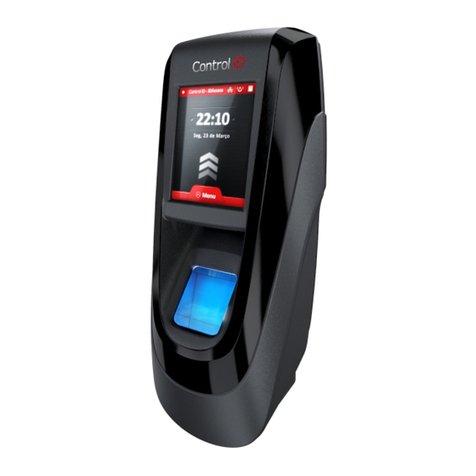
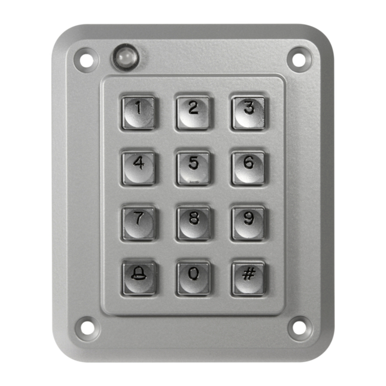
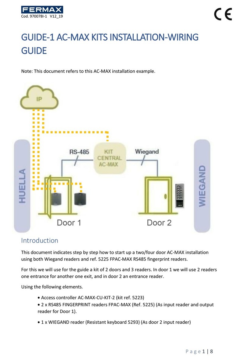
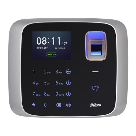
iGuard LM530 User manual


Federal Communications Commission (FCC) Statement
This Equipment has been tested and found to comply with the limits for a Class A
digital device, pursuant to Part 15 of the FCC rules. These limits are designed to
provide reasonable protection against harmful interference in a residential installation.
This equipment generates, uses and can radiate radio frequency energy and, if not
installed and used in accordance with the instructions, may cause harmful
interference to radio communications. However, there is no guarantee that
interference will not occur in a particular installation. If this equipment does cause
harmful interference to radio or television reception, which can be determined by
turning the equipment off and on, the user is encouraged to try to correct the
interference by one or more of the following measures:
Reorient or relocate the receiving antenna.
Increase the separation between the equipment and receiver.
Connect the equipment into an outlet on a circuit different from that to which the
receiver is connected.
Consult the dealer or an experienced radio/TV technician for help.
CE
EMC DIRECTIVE 89/336/EEC (EN55022 / EN55024)
Trade Name: iGuard
Model No: LM530

iGuard™ LM530 Operation Manual Version 1.0
- i -
User’s Notice
This manual contains detailed instructions and notes on the operation and use of the
product. For your safety and benefit, read this manual carefully before using the
product. Keep this manual in a handy place for quick reference.
Notes
Some illustrations in this manual might be slightly different from the product.
Certain options might not be available in some countries. For details, please
contact your local dealer.
Important
Contents of this manual are subject to change without prior notice. In no event will
the company be liable for direct, indirect, special, incidental, or consequential
damages as a result of handling or operating the product.
No part of this manual may be reproduced, transmitted, transcribed, stored in a
retrieval system, or translated into any language in any form or by any means
without the written permission of Lucky Technology Ltd.
Trademarks
iGuard®is registered trademark of Lucky Technology Ltd.
Microsoft®and Windows®are registered trademarks of Microsoft Corporation.
Other product names used herein are for identification purposes only and
might be trademarks of their respective companies. We disclaim any and all
rights to those marks.

iGuard™ LM530 Operation Manual Version 1.0
- ii -
Table of Content
INSTALLATION......................................................................................................................................1
PRE-INSTALLATION NOTES ....................................................................................................................1
INSTALLATION .......................................................................................................................................1
Power Requirements & Back EMF issue .......................................................................................1
When deciding where to install… ...................................................................................................2
Connect the Power & External Controls.........................................................................................2
Connect the Electric Door Strike ....................................................................................................3
Connect the Network......................................................................................................................4
POWER-UP ...........................................................................................................................................4
CONFIGURATION..............................................................................................................................5
Setting the date and time ...............................................................................................................5
Network Settings ............................................................................................................................6
Verifying the Network Connections ................................................................................................7
GETTING STARTED ..............................................................................................................................9
USER AUTHENTICATION .....................................................................................................................9
SMARTCARD.........................................................................................................................................9
Full Read / Write Mode.................................................................................................................10
Serial Number Only Mode............................................................................................................11
Smartcards Supported by iGuard.................................................................................................11
Adding New User with Smartcard ................................................................................................12
Verification with Smartcard...........................................................................................................13
ADDING &VERIFYING USER WITH FINGERPRINT (FOR LM530-FOSC ONLY)...........................................13
Adding New User with Fingerprint................................................................................................14
Verification....................................................................................................................................15
ADDING AND VERIFYING USER WITH PERSONAL PASSWORD..................................................................16
Adding User with Personal Password..........................................................................................16
Verification with Personal Password ............................................................................................17
VIEWING THE ACCESS LOG..................................................................................................................17
MASTER AND SLAVE MODE .............................................................................................................19
IN CASE OF NETWORK FAILURE.............................................................................................................20
BASIC MASTER /SLAVE CONFIGURATION..............................................................................................20
KEYPAD OPERATION.........................................................................................................................22
THE FUNCTION MENU ..........................................................................................................................22
Function 1: Add / Update User.....................................................................................................22
Function 2: Inactivate ID...............................................................................................................22
Function 3: Activate ID .................................................................................................................23
Function 4: Delete Fingerprint / ID ...............................................................................................23
Function 5: System Configuration................................................................................................24
Function 6: Set Password ............................................................................................................24
Function 7: Shutdown / Reset......................................................................................................25
Function 8: AutoMatch .................................................................................................................26
Function 9: Issue / Import Smartcard...........................................................................................27
Function 0: Advanced Feature .....................................................................................................29
Function A: Test Mode Toggle .....................................................................................................30
Function B: Open Door.................................................................................................................30
THE BACKSPACE KEY..........................................................................................................................30
USING THE WEB BROWSER .............................................................................................................32
TERMINAL...........................................................................................................................................33
Terminal Status ............................................................................................................................34
Terminal List.................................................................................................................................34
COMPANY...........................................................................................................................................35
Access Log...................................................................................................................................35

iGuard™ LM530 Operation Manual Version 1.0
- iii -
Daily In Out...................................................................................................................................38
Attendance ...................................................................................................................................38
Setup ............................................................................................................................................39
Event Log .....................................................................................................................................41
EMPLOYEE..........................................................................................................................................42
Employee Information ..................................................................................................................43
Employee List...............................................................................................................................44
DEPARTMENT......................................................................................................................................46
REPORT .............................................................................................................................................47
SYSTEM SETTING................................................................................................................................49
Device...........................................................................................................................................49
APPENDIX............................................................................................................................................63
FINGERPRINT ENROLLMENT.................................................................................................................63
IGUARDPAYROLL ................................................................................................................................64
REMOTE DOOR RELAY ........................................................................................................................67
Configuration................................................................................................................................67
CONNECTION DIAGRAM .......................................................................................................................70
Basic Connection..........................................................................................................................70
Basic Connection (Large Load)....................................................................................................71
Remote Relay...............................................................................................................................72
CONTACT INFORMATION ......................................................................................................................73

iGuard™ LM530 Operation Manual Version 1.0
- 1 -
INSTALLATION
Proper planning is the key to successful implementation of any technology project. While
the iGuard system is very easy to install and operate, there are some areas to consider
before you begin installation.
Pre-Installation Notes
iGuard is designed for indoor use. If you plan to install it outdoors, be aware that
exposing it to water, heat, or other harsh conditions can damage the device and it
may not operate properly.
Do not install iGuard next to heat sources or in direct sunlight.
To prevent electrical short-circuits or overload, power the iGuard independently
with the power supply provided. Do not share the power with other device such as
the electric door strike.
To increase the security level in access control applications, use the optional
Remote Relay together with the iGuard unit. This device is sold separately, and it
assures that malicious damage to or tampering with the iGuard does not result in a
release of the electric door strike. Please refer to the Appendix for more
information.
Make sure the Smartcard Company Code is properly set before assigning any
smartcard to users. This code is a configurable, 4-character code, which is to set
your iGuard system apart from any other iGuard system. Any smartcard with a
code that does not match is not recognized by the system. So once the smartcards
have been assigned, do not change this Company Code. Please refer to the
section “Using the Web Browser
System Setting
Device Setup
Basic
Company Code”(page 50) for more information.
Installation
Determine the location(s) for installing iGuard, external Remote Relay, door strike and
power supply line. Fasten the rear metal panel at the location where the iGuard unit will
be installed. Connect the iGuard unit with the power supply provided.
Power Requirements & Back EMF issue
iGuard requires DC 12V / 800mA switching power supply. Sharing power with other
devices, such as a door strike, is NOT recommended. This is because the potential back
EMF (Electromotive Force) generated by the door strike may affect the iGuard. If it is
necessary to share it with the door strike, a protection diode (1N4004 type) must be

iGuard™ LM530 Operation Manual Version 1.0
- 2 -
installed across the 12V power lines to the iGuard. Refer to the Connection Diagram in
the Appendix for more information.
Warning: Use ONLY the power supply provided. Do not use other power supplies since
this may lead to system failure, and poor or unreliable operation.
When deciding where to install…
iGuard is a wall-mounted unit with a miniscule footprint, and can be conveniently installed
anywhere. However, for access control applications, it is recommended that the iGuard
should be installed as close to the door as possible, so that the user can open the door
within the timeout period, which is 5 seconds by default. Also note the following points:
Make sure that air can circulate freely through the ventilation slots.
Do not install the product next to heat-emitting sources, or in a place subject to
direct sunlight and excessive dust.
Connect the Power & External Controls
iGuard provides easy-access terminals for connections to external controls, including Door
Strikes, Door Sensor and External Alarm.
Terminals
Description
Power
Power (12V DC)
The power requirement is 12V DC, 800mA. Connect it to the
power supply provided.

iGuard™ LM530 Operation Manual Version 1.0
- 3 -
Terminals
Description
3, 4 & 5
Door Strike
Terminal #3 & #4 are the normal-open (NO) pair, and terminal #4
& #5 are the normal-close (NC) pair. Connect the door strike to
either pair of these terminals according to the type of the electric
door strike.
6 & 7
Door Sensor (Optional)
This pair provides iGuard the current status of the door (i.e., open
/ close). If the door is left open for over 10 seconds, iGuard will
generate beep sounds to alarm.
8 & 9
External Alarm (Optional)
This pair is for the optional external alarm. In the case that the
device is forced open and removed from the wall during
operation, an internal case switch will connect this terminal pair,
which can optionally sound an external alarm.
RS - 485
(for Remote
Relay only)
Remote Relay Connector
This is to connect the iGuard to the optional Remote Door Relay
unit. Refer to the Appendix (p. 67) for more detail.
Wiegand
Wiegand Connector
iGuard can be used as a Wiegand Reader. This Wiegand
connector outputs the user ID to another Wiegand device in the
standard 26-bit format.
Remarks: Terminals / Connectors other than the above mentioned are reserved for
manufacturer use.
Connect the Electric Door Strike
Connect the Electric Door Strike to the Terminal Pair #3 & #4 for normal-open type, or the
pair #4 & #5 for normal-close type.
Internally, these terminals #3, #4 & #5 are connected directly to an internal relay, rating at
12V / 1Amp. If the door strike is within this current limit, it can be directly connected to
these terminals. If the current rating is above 1 Amp, a Remote Door Relay (sold
separately) must be used (see Appendix on page 67).
More details about the door strike connection are given in the connection diagrams in the
Appendix.
The administrator should examine each door that is to be controlled, and determine the
type of door (wood, glass, or metal), the swing direction, the desired in/out direction to be
controlled (unless the unit will authenticate both directions), and the type of frame (wood

iGuard™ LM530 Operation Manual Version 1.0
- 4 -
or metal). This information will be helpful for determining the type of lock that is to be
used with the iGuard. Please consult the dealer for more information about magnetic
locks, electric strikes, and other door hardware.
If the system is used solely for Time Attendance purposes, these terminals can be left
disconnected.
Connect the Network
iGuard is designed to be directly connected to the corporate computer network and to the
Internet via the standard RJ-45 cabling. By connecting it to the network, one can manage
& monitor the unit via any standard web browser, such as Microsoft Edge & Google
Chrome.
The connection is very straightforward as shown in the following picture:
Make sure the computer has installed and has been configured with the TCP/IP Protocols.
iGuard can also be connected directly to the PC via crossover RJ-45 cable.
Note: Please contact iGuard Technical Support at info@lucky.com.hk for technical
support.
Power-up
During power up, iGuard will perform a self-test, then it will enter the standby mode as
shown below: -
Description
LCD Display
1. Power Up –when iGuard is powering-up, it will perform a self-
test…
Initializing...

iGuard™ LM530 Operation Manual Version 1.0
- 5 -
Description
LCD Display
2. After about 10 sec., the device will load the system program…
iGuard System
Loading.....
3. After loading the system program, iGuard will enter the
Standby Mode and is now ready to set the date, time & the
network settings.
Wed Jan 24 12:00
ID #:_ IN
CONFIGURATION
Setting the date and time
The date and time must be properly set up so that iGuard can time stamp all the access &
time attendance records. iGuard automatically sync its clock with the SNTP Time
Server in the internet. It can also be done manually as follow:
Description
LCD Display
1. While in Standby Mode, press the Func key to enter the
Function Menu. You will be asked to enter the System
Administrator Password.
Enter Password:
_
2. Enter the System Administrator Password (default: 123).
Enter Password:
***_
3. Press the Func key to continue. The function menu will scroll
down slowly as shown.
Press 1:
Add/Update ID
:
Press 5: System
Configuration...
4. Enter 5to select the System Configuration menu. The
current firmware version & the IP address will be momentarily
shown, followed by the current date. If necessary, enter the
new date and then press the Func key to continue.
Ver: 6.0.1008
192.168.000.100
:
Date (M/D/Y):
01/24/2018
5. After pressing the Func key, the current time is displayed.
Enter the new time then press the Func key to continue.
Time (H:M:S):
13:24:43
6. The system will then ask for the Terminal ID, which is used to
identify the iGuard in your network. The default ID is “iGuard”.
This ID is important especially if you have more than one unit
installed.
Terminal ID:
iGuard
Note: iGuard can keep the date & time running without power for approximately one day.

iGuard™ LM530 Operation Manual Version 1.0
- 6 -
Network Settings
To connect iGuard directly to your corporate network, a device name & an IP address are
required. It is optional to use the DHCP server in the network to dynamically assign the IP
address, but it is suggested that a static IP address is to be used.
The following procedures describe how to assign the name (i.e., the Terminal ID), the IP
addresses, and other related network settings. Before proceeding the correct settings
should already be obtained from the network administrator.
Description
LCD Display
1. (…continue from step 6 above) Enter the name of the
device (e.g., A142). A more meaningful & descriptive
name, such as “front door”or “main entrance”, can be
assigned through the setup pages of the Web Interface
(discussed in next chapter).
Terminal ID:
A142_
2. Press Func key to continue, and then press 2to select
“Static IP” instead of DHCP for now.
DHCP/Static IP
(1/2)? Static
3. Press Func key to continue. You will then be asked to
enter the IP address of the device. The default is
192.168.0.100. Change this default value if necessary.
IP Address:
192.168.000.100
4. Press Func key, and then you will be asked to enter the
port number. Use the default value 80 for now.
Port Number:
80_
5. Press Func key to continue. Enter the subnet mask here
(e.g., 255.255.255.0).
SubnetMask:
255.255.255.000
6. Press Func key to continue. Enter the address of the
Default Gateway (e.g., 192.168.0.1).
Default Gateway:
192.168.000.001
7. Press Func key to continue. Enter the address of the
Domain Name Server (e.g., 1.1.1.1).
DNS:
001.001.001.001
8. Press Func key to continue. You will be asked if the
device is a Master or Slave device. This is useful in a
multi-device environment, where more than one iGuard
are connected to each other. Refer to the section “Master
& Slave Mode”for more detail.
Master/Slave:
(1/2)? Master
9. Press 1to select Master for now. You will be asked if the
device is connecting to iGuardPayroll or not.
iGuardPayroll is a free service to allow you to store user’s
data and access logs in our cloud server. Refer to the
appendix for more detail.
Use iGuardPayrol
(Yes/No) 1/2? Y
:
iGuardPayroll...
(Yes/No)? Y

iGuard™ LM530 Operation Manual Version 1.0
- 7 -
Description
LCD Display
10.Press 2to disable iGuardPayroll for now. When asked if
you would accept the changes, press 1to select Yes. The
system may then reset itself and return to Standby Mode.
OK to Accept Y/N
(1/2)? Yes
:
Wed Jan 24 12:01
ID #:_ IN
Warning: The IP address of the iGuard unit must be unique as in all other network
devices. Otherwise, it will cause a network error and the iGuard will not function properly.
Note: The Terminal ID is NOT required to be unique, but a unique ID is recommended if
multiple devices are installed in the same computer network, such as in a Master / Slave
configuration.
Verifying the Network Connections
One can test the above network settings by using a PC to ping the iGuard unit as follows:-
Open the Command Prompt on the PC.To open Command Prompt for Windows
machines, click Start and then type cmd, and then select Command Prompt.
Type ipconfig to check the IP address of the PC and make sure it is in the same
network as iGuard (i.e., the same subnet mask).
While still in the Command Prompt, use the ping command to ping the IP address
of the iGuard unit as shown below, which is 192.168.0.142 in this case.
If the ping responds the following, the IP is set properly and the unit is ready.
Microsoft Windows [Version 10.0.16299.125]
(c) 2017 Microsoft Corporation. All rights reserved.
C:\>ping 192.168.0.142
Pinging 192.168.0.142 with 32 bytes of data:
Reply from 192.168.0.142: bytes=32 time=2ms TTL=128
Reply from 192.168.0.142: bytes=32 time=1ms TTL=128
Reply from 192.168.0.142: bytes=32 time=1ms TTL=128
Reply from 192.168.0.142: bytes=32 time=1ms TTL=128
Ping statistics for 192.168.0.142:
Packets: Sent = 4, Received = 4, Lost = 0 (0% loss),
Approximate round trip times in milli-seconds:
Minimum = 1ms, Maximum = 2ms, Average = 1ms
C:\>

iGuard™ LM530 Operation Manual Version 1.0
- 8 -
Next, launch the PC web browser (e.g., Microsoft Edge or Google Chrome), and enter the
IP address http://192.168.0.142 (i.e., the IP Address of the iGuard), and the following
iGuard web interface will be shown in the browser window:-
Enter the default user name and password (admin / 123), and the following screen will
appear:-
At this stage, the basic configuration is complete, and iGuard is now ready to use.

iGuard™ LM530 Operation Manual Version 1.0
- 9 -
Getting Started
iGuard is a self-contained, platform independent access control and time attendance
device. Most of the basic operations, such as user registration and verification, can be
directly performed using the keypad of the unit itself without using the computer and the
web browser.
Other operations like connecting and configuring Master/Slave devices and issuing
smartcard, can also be done through the keypad.
More advanced features, such as setting the users’ access rights, retrieving the access
log and other reports, and connecting to the cloud service, require accessing the device
via the built-in web server through a web browser (e.g., Microsoft Edge or Google
Chrome).
User Authentication
There are three methods for user authentication. These are the Contactless Smartcard,
the Fingerprint (for model LM530-FOSC only) and the Personal Password.Each of these
methods can be used separately to authenticate a user.
Alternatively, smartcard and fingerprint / personal password can be combined together
during user authentication to achieve higher security level of verification.
This section discusses the basic operations of these three methods.
SmartCard
iGuard comes standard with built-in contactless smartcard reader. The System
Administrator can use smartcard to create a new user, or to assign a smartcard to an
existing user.
Smartcard allows almost-instant verification for users, and it comes in handy when the
device is used during the high-traffic period, for example, at the beginning of the day when
everyone gets to the office at around the same time.
Alternatively, for iGuard model with fingerprint sensor (LM530-FOSC), fingerprint
verification can also be done together with smartcard, to increase the verification’s
security level. In this case, after presenting the smartcard, the user will be asked to scan
his fingerprint for authentication.
iGuard operates in two smartcard modes: Full Read-Write mode and Serial-Number-Only
mode. It can be set with the built-in webpage at System Setting Device Basic
SmartCard Mode, as shown in the following screen:

iGuard™ LM530 Operation Manual Version 1.0
- 10 -
Full Read / Write Mode
In the Full-Read-Write mode, for each individual user, all the available user information
including the user name, personal password, access rights, and the fingerprint information
(if any), will be written to the Smartcard’s internal memory.

iGuard™ LM530 Operation Manual Version 1.0
- 11 -
Under this mode, administers can choose saving the users’ fingerprint information in both
the iGuard device and the smartcards at the same time, or just saving it to smartcards
only.
For privacy purpose, one can choose to save his fingerprint information to the smartcard
only.
The operation of writing data to smartcards involves accessing the internal memory of the
smartcards with special smartcard password and access rights, therefore, for security
reason, only specifically-formatted iGuard Smartcard (sold separately) can be used in this
mode.
Please contact the iGuard dealer or visit the manufacturer’s website
1
for more information
about purchasing the smartcards for this mode of operation.
Serial Number Only Mode
In the Serial-Number-Only mode, iGuard only reads the serial number of the smartcard.
The content of the smartcard content is ignored. The smartcard serial number is used to
identify each individual user. The user information is retrieved from iGuard’s internal
database rather than read from the smartcard for further verification and authentication.
Smartcards Supported by iGuard
Each mode supports different kinds of smartcards as follows:
ISO
Type
Full
Read / Write
S/N Only
ISO14443A
Mifare Classic
Mifare Classic 4K
Mifare Plus
Mifare Mini
Mifare Desfire / Desfire-EV1
Siemens Infineon
ISO18092
Sony Felica 2
e.g., the HK’s Octopus Card
Note: In the Full-Read-Write mode, only specifically-formatted iGuard Smartcard can be
used with the device. Please contact the iGuard dealer or visit the manufacturer’s website
for more information about purchasing the Smartcard.
1
http://www.lucky-tech.com
2
The Octopus Card commonly used in Hong Kong also uses this standard.

iGuard™ LM530 Operation Manual Version 1.0
- 12 -
Adding New User with Smartcard
Follow these steps to create a new user by issuing a new smartcard to the user:-
Description
LCD Display
1. While in Standby Mode, press the Func key to enter the
Function Menu. Enter the System Administrator Password
(default 123) and press Func key, then press 9to select the
item “Issue / Import Smartcard”.
Issue/Import
Card (1/2)? _
2. Enter 1to select “Issue Card”. You will then be asked to enter
the User ID.
Enter ID #
_
3. Enter the user ID # (e.g. A01). The ID can be of any length
from 1 to 10 characters, including the letters A & B.
Enter ID #
A01_
4. Press Func key to continue. If the ID does not exist, you will
be asked to confirm to create this new ID.
Create new ID...
Yes/No (1/2)? _
5. Press 1to select Yes, then the unit will prompt you to present
the Smartcard.
Waiting for
SmartCard...
6. Place a new Smartcard near the Keypad. Depending on the
selected smartcard mode, once the device has detected the
Smartcard, it will either update the card by writing the user
information to the card, or just assign the smartcard’s serial
number to the user.
Writing...
:
Issue OK!
7. Once it has finished updating the card, the unit will ask for the
next user ID for issuing another Smartcard. Press
backspace to return to Standby Mode.
Thu Aug 30 13:28
ID #:_ IN
In Full-Read-Write mode, all the available user information, including the user name,
personal password, access rights, and the fingerprint information (if any), will be written to
the Smartcard memory.
In Serial-Number-Only mode, iGuard will only read the serial number of the smartcard,
and assign this serial number to the user, without writing any user information to the
smartcard.

iGuard™ LM530 Operation Manual Version 1.0
- 13 -
Verification with Smartcard
Verification with Smartcard is simple and straight forward, and is illustrated in the following
steps:-
Description
LCD Display
1. While in Standby Mode, present the smart card near the
keypad. Depending on the card type, the unit will either read
the card’s s/n only or read the whole content of the card. If
the card is valid, the user will be authorized as indicated in the
display. The unit will return to Standby Mode afterwards, and
it is ready for the next card.
A01
Authorized!
:
Thu Aug 30 13:36
ID #:_ IN
Note: To achieve higher security level, iGuard can be configured to ask for the fingerprint
image or Personal Password after presenting the smartcard for verification. It will be
discussed in more detail in the next section under the heading “Function 9: Issue / Import
Card”.
Adding & Verifying user with Fingerprint (for LM530-FOSC only)
(This section is for iGuard with the optional fingerprint sensor only)
iGuard is optionally equipped with fingerprint sensor for fingerprint verification.
During the fingerprint enrollment process, the unit will ask for two fingerprint images for
each person, and the information of the images (i.e., minutiae
3
) is extracted and stored in
the internal database for later verification.
Each person must register two fingers: one as the primary and the other one as the
secondary. Therefore, if the person’s primary finger is temporarily not suitable, such as
when the finger is wounded, he can still use his secondary finger for verification.
During the process, each fingerprint image is captured two times for minutiae analysis and
extraction. If the quality of any one of these two images is not good enough, the user will
be asked to re-scan the two images again.
The two thumbs are suggested as the primary & secondary fingers. This is because the
thumbs are usually bigger and can cover the scanner area better.
Hints for Capturing Fingerprint Images
Place the thumb flat on the fingerprint sensor using the pad, not the tip, of the thumb. The
tip of the thumb contains the fewest minutia points, so place the thumb as flat as possible
on the sensor to generate the fullest possible image.
3
Minutiae is the mathematical representation of the fingerprint image. It cannot be used to revert the
original fingerprint image.

iGuard™ LM530 Operation Manual Version 1.0
- 14 -
The Core
The Tip
The core of the fingerprint containing the most minutia points is usually located opposite
the cuticle. Center the cuticle in the sensor window to maximize the number of minutia
points.
IMPORTANT: During the enrollment process, position the center of the fingerprint of the
thumb to the center of the fingerprint sensor. The center of the fingerprint contains the
most minutia points from which the fingerprint sensor can extract. A good fingerprint
image captured during the enrollment process can significantly reduce the false-reject rate
during later verification.
Adding New User with Fingerprint
The following steps will show how to register the user’s fingerprint data:-
Description
LCD Display
1. While in Standby Mode, press the Func key to enter the
Function Menu. Enter the System Administrator Password
(default 123) and press Func key, then press 1to select
“Add/Update ID”menu.
By Finger/Passwd
(1/2)? _
2. Press 1to select “By Finger”, then you will be asked to enter
the user ID.
Enter ID #:
_
3. Enter the user ID # (e.g. A02). The ID can be of any length
from 1 to 10 characters.
Enter ID #:
A02_
4. Press the Func key to confirm the ID #. You will be asked to
place the finger on the fingerprint scanner.
Scanning 1/2
Waiting finger..
5. Place the primary finger on the scanner for scanning.
Afterwards, you will be asked to scan this same finger again.
Press Func to
scan 2 of 2...
6. Remove the finger from the scanner and then press Func.
Then scan the same finger again for the 2nd time. After that,
iGuard will analyze and extract the data from the two images.
If the image quality is good, it will then ask for the secondary
finger. Otherwise, it will ask to scan the 1st finger again.
Analyzing...
:
Analyzing...OK
:
Press Func to
scan 2nd Finger

iGuard™ LM530 Operation Manual Version 1.0
- 15 -
Description
LCD Display
7. Press Func, then repeat the procedure for the secondary
finger. After successfully scanning the 2nd finger, iGuard will
ask if the AutoMatch4feature is to be enabled for this user.
Add to AutoMatch
Yes/No (1/2)?_
8. Press 1to enable this feature for this user. iGuard will then
update the internal database and the fingerprint sensor, and
prompt for more users.
Updating...
:
ID# A02
Added OK!
:
Enter ID#:
_
9. Press the Backspace to return to the Standby mode.
Thu Aug 30 13:34
ID #:_ IN
Note: If the user ID “A02” already exists, iGuard will prompt and ask whether to overwrite
the existing fingerprint information or not.
In case of poor fingerprint image, for example, if the skin of a user is too dry or too wet,
the user might experience difficulty when registering the fingerprint image. In this case,
iGuard will show related messages indicating the fingerprint quality problem.
Please refer to the Fingerprint Enrollment section in the Appendix for more information.
Verification
iGuard uses the enrolled fingerprint information to identify the person. The verification
process is very straightforward, and is illustrated in the following steps: -
Description
LCD Display
1. While in Standby Mode, key in the user ID number (e.g.,
A02).
Thu Aug 30 13:36
A02_ IN
2. Place either one of the registered fingers on the fingerprint
scanner. You should place the finger the same way that you
did during the enrollment procedure. The device will
automatically start scanning after detecting the presence of
the finger.
Scanning...
A02_
:
Verifying...
4
AutoMatch is a feature that allows users to get authenticated by simply placing the finger on the scanner,
without first entering the user ID. The maximum number of AutoMatch Users is 100.
Table of contents
