select solar 05002MK03 User manual

Motorhome Solar Panel Kits October 2011 Page 1of 4
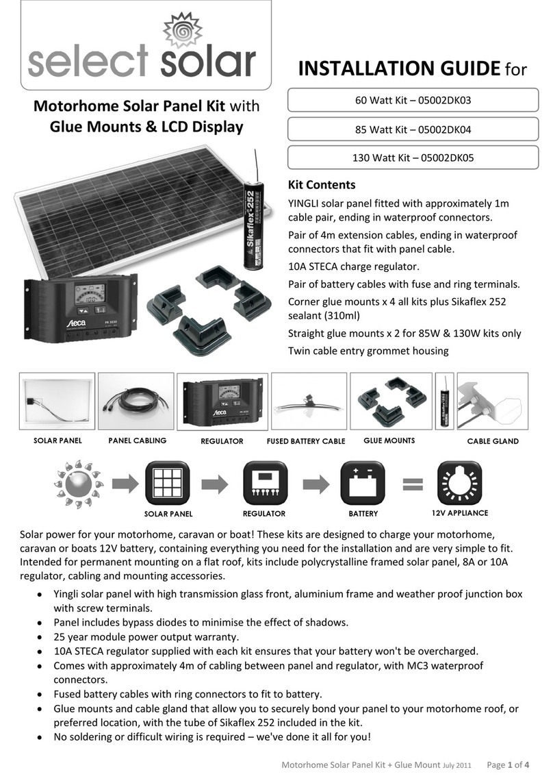
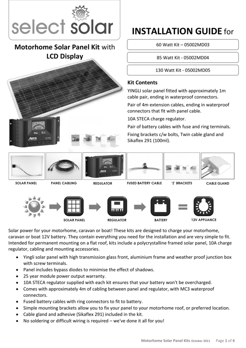
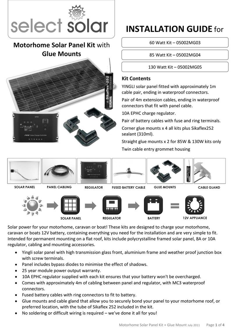
Kit Contents
YINGLI solar panel fitted with approximately 1m
cable pair, ending in waterproof connectors.
Pair of 4m extension cables, ending in waterproof
connectors that fit with panel cable.
10A EPHC charge regulator.
Pair of battery cables with fuse and ring terminals.
Fixing brackets c/w bolts, Twin cable gland and
Sikaflex 291 (100ml).
Solar power for your motorhome, caravan or boat! These kits are designed to charge your motorhome,
caravan or boat 12V battery. They contain everything you need for the installation and are very simple to fit.
Intended for permanent mounting on a flat roof, kits include a polycrystalline framed solar panel, 10A charge
regulator, cabling and mounting accessories.
Yingli solar panel with high transmission glass front, aluminium frame and weather proof junction box
with screw terminals.
Panel includes bypass diodes to minimise the effect of shadows.
25 year module power output warranty.
10A EPHC regulator supplied with each kit ensures that your battery won't be overcharged.
Comes with approximately 4m of cabling between panel and regulator, with MC3 waterproof
connectors.
Fused battery cables with ring connectors to fit to battery.
Simple mounting brackets allow you to fix your panel to your motorhome roof, or preferred location.
Cable gland and adhesive (Sikaflex 291) included in the kit.
No soldering or difficult wiring is required –we've done it all for you!
Motorhome Solar Panel Kit
60 Watt Kit - 05002MK03
85 Watt Kit - 05002MK04
130 Watt Kit - 05002MK05
SOLAR PANEL
REGULATOR
BATTERY
12V APPLIANCE
SOLAR PANEL
PANEL CABLING
REGULATOR
FUSED BATTERY CABLE
‘Z’ BRACKETS
CABLE GLAND
INSTALLATION GUIDE for

Motorhome Solar Panel Kits October 2011 Page 2of 4
1 - Preparation
Our solar panels are supplied already pre-wired for easy installation.
Before fixing the solar panel to your motorhome or boat, it is usually best to plug the 3m extension
cables into the connectors fitted to the wire coming from the back of the solar panel. This allows you
to position the panel without having to worry about access to rear.
The cables are identified as ‘-ve and ‘+ve’ by both tags and colour.
The cross sectional size of the extension cables is 2.5mm2, should you wish to extend them further.
2 - Fitting the Panel
The position of your solar panel should be considered carefully
allowing for the physical requirements of its mounting,
obstructions on the surface being mounted on and proximity to
where you will fit the charge regulator. It is also recommended
that you consider your wiring route prior to making any holes in
the roof.
You should leave a minimum clearance gap of 10mm beneath the
panel, for heat dissipation from the panel. A panel becomes less
efficient when it becomes too hot.
There are two types of ‘Z’ brackets depending on model type
supplied, but the principle of fitting remains the same, in that the
brackets should first be bolted to the underside of the solar panel
frame.
Subject to your roof type the panel can now be fixed to your
motorhome or boat, as appropriate.
Please take care that there is sufficient roof structure to permit
the secure fixing and to withstand loads generated when
travelling.
As each application is different, it is the ‘fitters’ own responsibility
to ensure the panel is securely fixed to the roof or structure.
Please also note that an appropriate sealant or barrier should be
used to prevent moisture ingress inside the motorhome or boat.
At an appropriate point on the motorhome roof the twin cable entry
gland housing should be installed, with the cable entry gland/glands
facing down.
Assemble the housing and glands, ensuring that glands are secure
and tight to the body.
After making an appropriate sized access hole in the motorhome
for the cabling, bond the plastic housing to the motorhome/boat,
using the sealant provided. It may be easier to feed the wiring
through the housing and glands, prior to bonding the housing,
depending on your situation. Follow the manufacturer’s
instructions and safety guidelines for the sealant.
Ensure cable glands are tightened and that cable is secure.
On exposure to sunlight PV
panels immediately generate
an electric current and
although the voltage
produced is generally low,
touching bare wires or
terminals can cause shock and
burns. If preferred place a
cloth or card over the module
to prevent the panel from
generating power, while you
are installing it.
CAUTION
During use please be aware of
shadows cast from
surrounding buildings and
trees etc., as this will affect
the efficiency and power
generated from the solar
panel.
It is good practice to keep the
panel clean from dirt and
debris at all times and
cleaned using a mild solution
of soap and water.

Motorhome Solar Panel Kits October 2011 Page 3of 4
3 - Fitting the Charge Regulator
The charge regulator should be fitted in a dry, ventilated environment as
close as possible to the battery, to reduce voltage drop. Please refer to
and follow instructions that come with the regulator supplied.
Before installing the charge regulator be sure to unplug the cables
from the solar panel.
The stripped and tinned ends of the extension cables are
connected via screw terminals to the base of the regulator.
Please ensure that the ‘+ve’ and ‘-ve’ leads are connected the
correct way round, observing polarity at all times.
The fused battery cable can now be fitted in a similar manner,
ensuring the correct polarity at all times. Should you need to
modify the length of these to reach the battery, please bear in
mind that they should remain as short as possible at all times.
Plug the solar panel cables back together.
The final assembly should look similar to the photograph shown.
Please note that although it is possible to connect a load such as a light
directly to the charge regulator, for motorhome and boat applications this
is not recommended, due to the load limit on this circuit.
4 - Safety and Handling Precautions
This kit has been designed for mobile leisure applications and as such ring terminals are provided for
the battery connections, as crocodile clips are ONLY suitable for stationary batteries.
Always ensure the correct polarity.
Stripped cable ends should always be tinned and always use electrically insulated tools.
For more information please see our range of downloadable guides, including ‘An Explanation of Solar
Panel Basics’, available from www.selectsolar.co.uk.
On exposure to sunlight PV panels immediately generate an electric current and although the voltage
produced is generally low, touching bare wires or terminals can cause shock and burns. If preferred
place a cloth or card over the module to prevent the panel from generating power.
This product has been designed to be robust. However, we recommend that the module is carefully
handled and stored at all times as forceful impacts can cause irreparable damage and void warranty.
Never twist, bend or otherwise deform the panel, as this will invalidate the warranty.
Drilling or welding the frame is NOT recommended and will invalidate the warranty.
Never use a device that concentrates the light on the modules as this could seriously damage them
and invalidate the warranty.
Connect the charge regulator
to the battery first and then
connect the solar panel to the
regulator.
Warranty may otherwise be
affected.
IMPORTANT
FUSE
Connect the
Panel last

Motorhome Solar Panel Kits October 2011 Page 4of 4
5 –Technical Specifications
Panel Characteristics
Comprising 36 ‘Polycrystalline’cells connected in series and capable of
charging 12V batteries.
Bypass diodes included to avoid hot spot effect.
Heavy duty anodised aluminium frame provides high wind resistance
and convenient mounting access.
Cells are laminated between high transmissivity, low iron, 3mm
tempered glass and a sheet of TPT material, with two sheets of EVA to
prevent moisture entering the module.
Installation holes for standard brackets systems are provided.
Weather-proof junction box.
Panels are manufactured in accordance with IEC 61215 and come with
25 years limited output warranty.
Electrical Charecteristics 60w 85W 130W
Typical maximum power (Wp) 60 85 130
Open circuit voltage (Voc) 22.0 22.0 22.0
Optimum operating voltage (Vmp) 17.5 17.5 17.5
Optimum operating current (Imp) 3.40 4.86 7.43
Short circuit current (Isc) 3.80 5.60 8.44
Standard Parameters
Nominal operating cell temperature (NOCT) 46+/- 2oC
Current temperature coefficient (Isc) +0.10%/oC
Voltage temperature coefficient (Voc) -0.38%/oC
Power temperature coefficient (Wp) +0.47%/oC
Edge grounding <=1ohm
Wind resistance 2400Pa
Maximum system voltage 1000V
This information represents the output of typical panels in 12V configuration. This data is based on measurements made in
accordance with Standard Test Conditions (STC) 1000W/m2, AM 1.5 with a cell temperature of 25oC.
Standard Parameters 60W 85W 130W
Weight 6.5Kg 8.4Kg 16Kg
Size of panel (mm) 770 x 660 x 35 660 x 1010 x 35 1470 x 680 x 50
Polycrystalline cells 36 36 36
Select Solar Ltd
Waterpark Storage, 4 Ermin Way Barns, The Street,
Latton, Swindon, Wiltshire, SN6 6DN.
www.selectsolar.co.uk
phone: 01793 752 032
This manual suits for next models
2
Other select solar Solar Panel manuals
Popular Solar Panel manuals by other brands
Sunforce
Sunforce 37010 manual
Solahart
Solahart HSL60P6-PB-1-250 Owner's guide and installation instructions

STIEBEL ELTRON
STIEBEL ELTRON SOL 27 PREMIUM S Operation and installation
Velux
Velux GGL Installation
vikram solar
vikram solar SOMERA VSMD.72 Series installation manual
Sharp
Sharp ND-AF C Series installation manual

Sanyo
Sanyo HIP-215NKHA5 General installation manual

SolarWorld
SolarWorld Suntub Design and installation manual

Xiamen Antai New Energy
Xiamen Antai New Energy Antai Rail? installation manual
PowerFilm
PowerFilm R-14 operating instructions
Klein Tools
Klein Tools 29250 instruction manual
Panasonic
Panasonic HIT VBHN320KA01 General installation manual
