Siliken Atakama ATK-P60 User manual

Edition 01A Date: 14/04/2011
Ronda Isaac Peral y Caballero
Parque Tecnológico
46980 Paterna - Valencia
Tel : +34 902 41 22 33
Fax: +34 96 070 92 65
info@siliken com
www.siliken.com
Photovoltaic module
Instructions for use

SILIKEN appreciates your support for our products.
We recommend that you read this instruction manual
carefully in its entirely before handling the photovoltaic
module.

Table of contents
Important safety instructions
Product description
Recommendations for use
Product certificates and guarantee
By-pass diodes
Operating voltage
Protection fuses
Warnings and electrical hazards
Current-voltage curves
Mechanical assem ly instructions
Module maintenance
Module frame grounding
Declaration of CE conformity
........................................................................
.......................................................................................
..........................................................................
...............................................................
..........................................................................................
......................................................................................
.........................................................................................
..................................................................
...............................................................................
...............................................................
..................................................................................
.............................................................................
.......................................................................
3
4
6
8
10
13
14
16
20
22
33
35
41
1
2
3
4
5
6
7
8
9
10
11
12
13
Safety instructions
3
This instruction manual and the product la els contain a series of important
safety messages. They should e read carefully efore handling or connecting
the photovoltaic module since the module produces electricity as soon as the
cells are exposed to sunlight.
The safety warning sym ol is shown efore each safety message included in
this instructions manual. This sym ol indicates that there is a personal safety
hazard which would affect oth you and others and cause damage to the
products or other property.
This user manual must not contradict any regulation that could have changed
since the manual
s last pu lication date.
Warning: any fault in the module caused by failure to comply with the
warnings stipulated in this instructions manual will lead to the complete
withdrawal of the modules guarantee, together with the full exoneration
of SILIK N from any responsibility derived of any kind.
!
!

Your photovoltaic Standard module is comprised of the following elements:
1 FRAM
In anodised aluminium; providing a system for anchoring the module
to the support structure.
2 GLASS
Ultra-transparent 3.2 mm thick tempered glass; providing rigidity to the
unit and protecting the active surface of the cells.
3 and 5 VA
(Ethylene Vinyl Acetate); its function is to encapsulate the cell circuit
4 C LLS
Highly efficient crystalline silicon solar cells. These generate the electricity.
6 BACK ISOLATION SH T
Providing electrical insulation to the rear surface of the module.
7 CONN CTION BOX.
IP65 specification. Providing a simple method of electrically connecting
the module to the rest of the installation.
Product description
4
1
2
3
4
5
6
7
Recommendations for use
5
Ensure that the module is located appropriately: it must not e placed
eneath the shade of streetlights, trees, other uildings or even shade
produced y other modules. Electricity production can e considera ly
reduced y the effect of shade.
Install the PV module allowing air to circulate freely (see also section 6
of this manual). This will facilitate the natural ventilation of the module.
The module is designed to work in temperatures etween -40
ºC and
+85ºC (-40ºF and +185ºF).
In addition, oth polycrystalline modules
produce more energy in lower temperatures. Therefore, proper ventilation
favors higher power generation.
It is important to orient the active surface of the modules towards the
south as much as possi le in the northern hemisphere, and towards the
north as much as possi le in the southern hemisphere.
The metal support structure for the photovoltaic modules should e
connected to ground in the manner indicated in the Low Voltage Directive
93/68/EEC and 2006/95/EEC and National Electrical Code.
Ensure that the ca les of the installation that connect modules to other
modules, as well as those that lead to the load regulator, atteries or
any other part of the installation, are not too tight since this could damage
module connections or the ca les themselves. Use ca le ties or ca le
clamps to fix the ca les to the structure.
Do not leave connectors unplugged for long periods of time; dirt may

6
prevent su sequent connection. We recommend that the modules are
connected in short-circuit to avoid this.
Respect the electrical polarity of the modules. You must remem er that
they are direct current modules and, as such, direct current is required
for their correct operation. In addition, when connecting the different
components of an isolated installation, you must always connect the
atteries first, followed y the module, and finally the power supply.
Do not use the connection ox or the connection ca les to hold or
transport the module. You could damage some of its components and
affect its waterproofness as well as the electrical security.
Always handle the module with care, even if it has the aluminium frame.
Any low on the glass or on a corner of the frame could deform it enough
to reak the glass.
Do not dismantle, modify or adapt the PV module. Do not remove any
part or the identification la el from a PV module installed y Siliken. If
you do so, the guarantee will e invalid. Do not apply paint or adhesives
to the ack side of the PV module.
WARNING: SILIK N shall not be held responsible or liable for any
possible decrease in the electricity production of the photovoltaic
module supplied, nor shall it consider said reduction to be a
manufacturing defect if it is the result of the failure to observe the
recommendations for use described herein.
!
Recommendations for use

7
Product certificates and guarantee
Atakama photovoltaic standard modules have een designed and
manufactured in accordance with (I C) N 61215, UL 1703 standards
and complies with the safety standards Qualification of photovoltaic
modules I C61730 class A (class II). In order to comply with these
international standards, high quality and dura le materials have een
used. In addition, Atakama has a series of rigorous quality controls
esta lished for each phase of the production process along with a final
quality control of the output power for all manufactured modules.
Siliken provides a 10 year guarantee for the materials of the photovoltaic
module and against any possi le defects of the photovoltaic module
due to the manufacturing process.
Product certificates and guarantee

8
By-pass diodes
The photovoltaic module must e protected with y-pass diodes. The
a sence of these diodes could cause the photovoltaic module to
malfunction or even ultimately lead to its destruction as it could catch
on fire. Siliken delivers its modules with y-pass diodes included inside
the connections ox.
The photovoltaic cells have two operating modes: it operates as a current
generator or as a current consumer. A cell exposed to solar radiation
provides a current ranging etween 6 and 8 amps with a potential
difference of around 0.6 volts. However, when a cell is partially shaded,
y the leaves of a tree for example, it starts to consume the electricity
generated y the other cells to which it is connected. At the area of the
cell that changes from a sunlit area to a shaded area, an effect known
as a "hot-spot" occurs where y, due to the circulation of current, the
overheating produced is such that it may set the materials on fire and
destroy the module. The maximum num er of cells connected in series
per diode is 20 cells for Atakama PV modules.
9
By-pass diodes
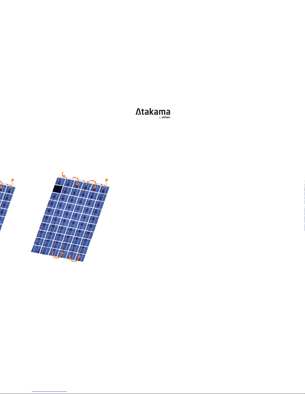
Normal operation Operation with the cell in the shade

By-pass diodes
10
WARNING: For the aforementioned reasons, it is important that the
diodes are not removed from the connection box.
In the event of y-pass diode failure, they must e replaced with original
y-pass diode spares and y personnel authorized and trained y Siliken.
From the moment that the failure in the diodes occurs and until they are
replaced, the affected photovoltaic module(s) must remain disconnected
from the other modules on the photovoltaic array, thus guaranteeing that
the circuit remains open. In any event, the decision to change the diodes
is the responsi ility of Siliken.
WARNING: Failure to use original spares or parts replaced by
personnel without the authorisation of SILIK N, etc., shall lead to
the withdrawal of the guarantee of the photovoltaic module and
SILIK N shall automatically be exonerated from any responsibility
for damage caused to property or harm caused to people.
!
!

Operating voltage
11
The maximum voltage of the system is 1000 V in Europe (see module
la el) and 600 V in USA (see module la el). The maximum num er of
modules to e connected in series (in cell temperature conditions of
77ºF / 25°C),
is 16 in USA and 24 in Europe
WARNING: the value for the maximum number of modules must be
corrected based their location and in accordance with the correction
parameters provided in the formula, since the voltage increases as
the temperature decreases. Calculate the value based on the lowest
temperature in the region where the modules will be installed.
!
Maximum system voltage
V
oc77°F
+ (( Ta - 77 ) x
no cell
x (-0.00215))
Max. no. of modules

Protection fuses
12
Attention: Under normal conditions, a photovoltaic module is likely
to experience conditions that produce more current and/or voltage
than reported at standard test conditions. Accordingly, the values
of ISC and VOC marked on this module should be multiplied by a
factor of 1.25 when determining component voltage ratings,
conductor ampacities, fuse sizes, and size of controls connected
to the PV output.
Attention: Refer to Section 690-8 of the National lectrical Code
for an additional multiplying factor of 125 percent (80 percent
derating) which may be applicable.
For field connections, use minimum No.
10 AWG copper wires insulated
for a minimum of 194°F / 90 ºC.
Once the modules are connected in series to o tain the correct input
voltage for each type of inverter it is essential that protection fuses are
located etween the inverter and each series. These fuses will facilitate
maintenance and control tasks, ut they will mainly protect the series
from each other should the polarity of one of the series of modules e
incorrectly connected.
Series fuse (overcurrent protection) rating of 15 A.
!
!

13
!
The design level current for these fuses must e multiplied y a factor
of 1.25 times the Isc of the photovoltaic module measured under standard
test conditions (92.94 W/ft2 and 77 ºC) / (1,000 W/m2 and 25°C). The
fuses must e suita le for direct current systems, with a reaking
capacity greater than the sum of the intensities of the series of connected
modules, using the method indicated in the National Electrical Code.
Failure to install this type of protection, in the event of an incorrect
positive and negative polarity connection, will cause the reversed series
to act as an electricity receiver causing severe damage to oth the
diodes and the other electrical components of the modules.
WARNING: Failure to comply with the provisions of this section will
lead to the loss of guarantee and the exoneration of Siliken from any
type of responsibility for damage to property or injury to people.
Protection fuses

Warnings and electrical hazards
14
The installation, handling and maintenance of the photovoltaic modules
must e carried out y qualified personnel duly equipped with individual
protections.
For information purposes, these protections include: safety oots with
insulation for a ove 1000V, gloves with 1000V insulation, as well as a
helmet and appropriate clothes.
Contact with VAC (VDC) voltage equal or higher than 30 V is potentially
dangerous. Do not use PV modules with different electrical or physical
configurations in a single PV system. Keep children away from the system
and the PV modules during installation. Do not carry out the installation
in heavy rain or wind.
For handling electrical components, always use appropriate tools covered
with insulating materials. It is recommended to avoid handling modules
in humid conditions. Before handling and installing PV modules, remove
your rings and other metal jewels.
It is important to remem er that the active front panel of the module is
made of glass and can reak if it receives an impact. In cases of roken
glass, the module must not e installed as it will have lost the electrical
insulation of the cells and will have a much lower performance level.

Warnings and electrical hazards
15
Do not allow o jects to fall on the photovoltaic module, and do not sit on,
lean on,
or walk on the photovoltaic module, on either side (glass or rear
sheet), given that it could cause the cells to reak and therefore significantly
lower the power and energy performance of the modules.
Do not open the connection ox of the photovoltaic module. The cover
of the connection ox has a safety seal to guarantee to the customer
that it has een correctly sealed to provide IP65 level of protection. If
the cover is not correctly sealed, there is a risk of damage to the module
due to water ingress.
Do not disconnect the terminals of the modules if they are electrically
connected to other devices of the system. Before loosening connectors,
disconnect the modules from the inverter or the attery charger using
switches. Before handling any electrical parts of the PV installation,
cover the active surface of the module from sun light.
Do not use mirrors or magnifying lenses to concentrate light on the PV
modules, they were not designed for this.
When handling and installing the module, we recommend covering the
active surface of the photovoltaic module since the modules generate
electricity when they are exposed to any source of light even when they
are not connected to any other device.

Do not remove any of the modules components or remove the technical
specifications la el.
Do not place the installation near to any possi le source of inflamma le
gases or vapors, since the photovoltaic modules can cause sparks just
like any other electrical component.
Always ensure the installation is equipped with protection devices against
electrical hazards.
Remem er that when the modules are connected in series, the voltage
present will e the sum total of the voltage from each module, and when
the modules are connected in parallel, the current present will e the
sum total of the current from each module. This means that an installation
with various modules may contain high levels of voltage and current.
When screwing the frame of the module to the structure, avoid ru ing
against the plastic insulation on the rear surface of the module (Tedlar)
with the tool or elements protruding from the structure ecause this
could cause the plastic to tear, causing a loss of electrical insulation.
The PV module produces power even with a roken glass or ack sheet.
Do not dispose of the module in containers or dumping sites, this can
e dangerous. If the glass or the ack sheet is roken, in case of
Warnings and electrical hazards
16

Warnings and electrical hazards
17
!
electrical failure or if the service life of the module ends due to any cause
in general, please contact Siliken to appropriately eliminate and/or recycle
the product according to American/European norms.
Consult the fire security regulations, norms and prerequisites for uildings
and structures with your local authorities. Keep in mind that a roof-top
construction and installation may affect the uilding
s fire security; erroneous
installation of PV modules can increase this risk in case of fire. The
assem ly is to e mounted over a fire resistant roof covering rated for
the application.
The modules are qualified for application class A: Hazardous voltage
(IEC 61730: higher than 50V DC; EN 61730: higher than 120V), hazardous
power applications (higher than 240W) where general contact access
is anticipated (Modules qualified for safety through EN IEC 61730-1 and
-2 within this application class are considered to meet the requirements
for Safety Class II.
WARNING: Failure to comply with the provisions of this section
will lead to the loss of guarantee and the exoneration of Siliken
from any type of responsibility for damage to property or injury to
people.

urrent-voltage curves
18
The graphs of the technical data sheets show the ehaviour of the
photovoltaic modules. Two types of Current-Voltage curves (I-V) are
shown:
- At different radiations and constant temperature (77 ºF / 25°C).
- At different temperature and constant radiation (92.94 W/ft2 / 1000 W/m2).
The standard test conditions or STC used for module la elling are:
Radiation = 92.94 W/ft2 / 1000 W/m2
Cell temperature = 77 ºF / 25 ºC
Air Mass = 1.5
It must e noted that the voltage and current ehaviour of the cells
depends on the solar radiation and temperature. Therefore, the actual
operating conditions of a photovoltaic module will depend on the region
where the module is installed and the am ient conditions in that region.
The voltage dependence in relation to radiation is defined y a logarithmic
function: at low radiation levels a high voltage is o tained. However,
the current dependence in relation to radiation is defined y a linear
function: it increases in direct proportion to the increase in solar radiation.

19
The voltage and current dependence with temperature is defined y a
linear function. On one hand the voltage decreases as the temperature
increases at a ratio of 2.15 mV/ ºC per cell in series. On the other, the
current increases at +3.50 mA/ºC. Therefore, of the 7.5 to 8 amps that
the module is capa le of generating at 77º F / 25°C, the current increases
slightly with each degree centigrade of increase in the module temperature,
while the voltage decreases.
In general, we o serve a decrease of the photovoltaic module power as
the operating temperature increases, at a ratio of -0.47%/ºC. For example,
a module of 220 Wp will lose 0.95 Wp for every additional °C in the cells.
The module operates at etween 122 and 158 ºF / 50 and 70°C when
it generates electricity with radiation of etween 800 and 1100 W/m2
and a wind speed of less than 1 m/s.
urrent-voltage curves
This manual suits for next models
4
Table of contents
Other Siliken Solar Panel manuals

Popular Solar Panel manuals by other brands


HeimVision
HeimVision HMS1 quick start guide

XAG
XAG GNSS RTK Fix Station installation guide

jeri
jeri JER-120-SP-AG user manual

Viessmann
Viessmann Vitosol 200-T installation instructions

Viessmann
Viessmann VITOSOL-F installation instructions

brennenstuhl
brennenstuhl SOL SH0805 P1 IP44 Instructions for installation & use


