Baxi Solarflo User manual

© Baxi Heating UK Ltd 2011
SolarfloTM
Evacuated Tube Collector
Please read these instructions before installing or commissioning.
SolarfloTM (Solar Thermal Domestic Hot Water System) should only
be installed by a competent person.
PLEASE LEAVE THESE INSTRUCTIONS WITH THE USER
FOR SAFE KEEPING.
User Guide

1.0 Installation and Handover
1.1 Information
When your SolarfloTM domestic water heating system was
installed the installer should have fully commissioned the
system and left it in working order. Following this they should
have explained the system, its function and control including:
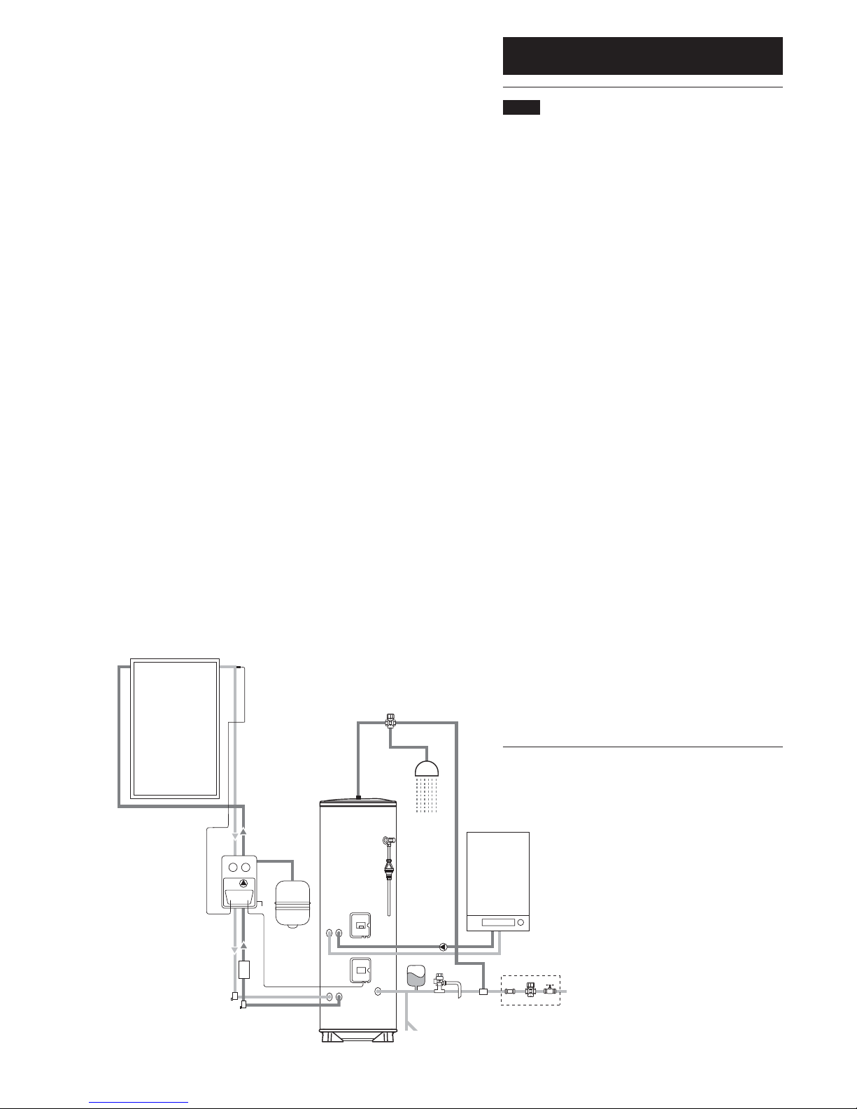
Heating by solar
Explained how the cylinder is heated when there is sufficient
solar energy.
Heating by auxiliary heating source
Explained how the cylinder is heated if additional heat input is
required due to insufficient solar energy being available (little
or no sun) or additional quantities of hot water are required.
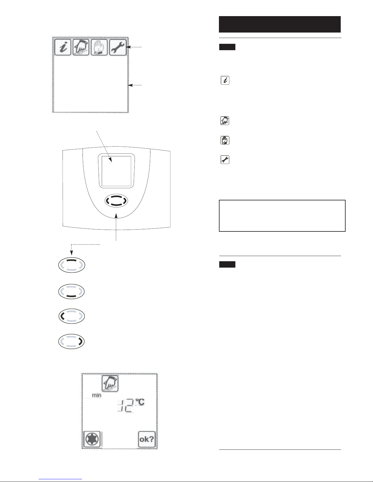
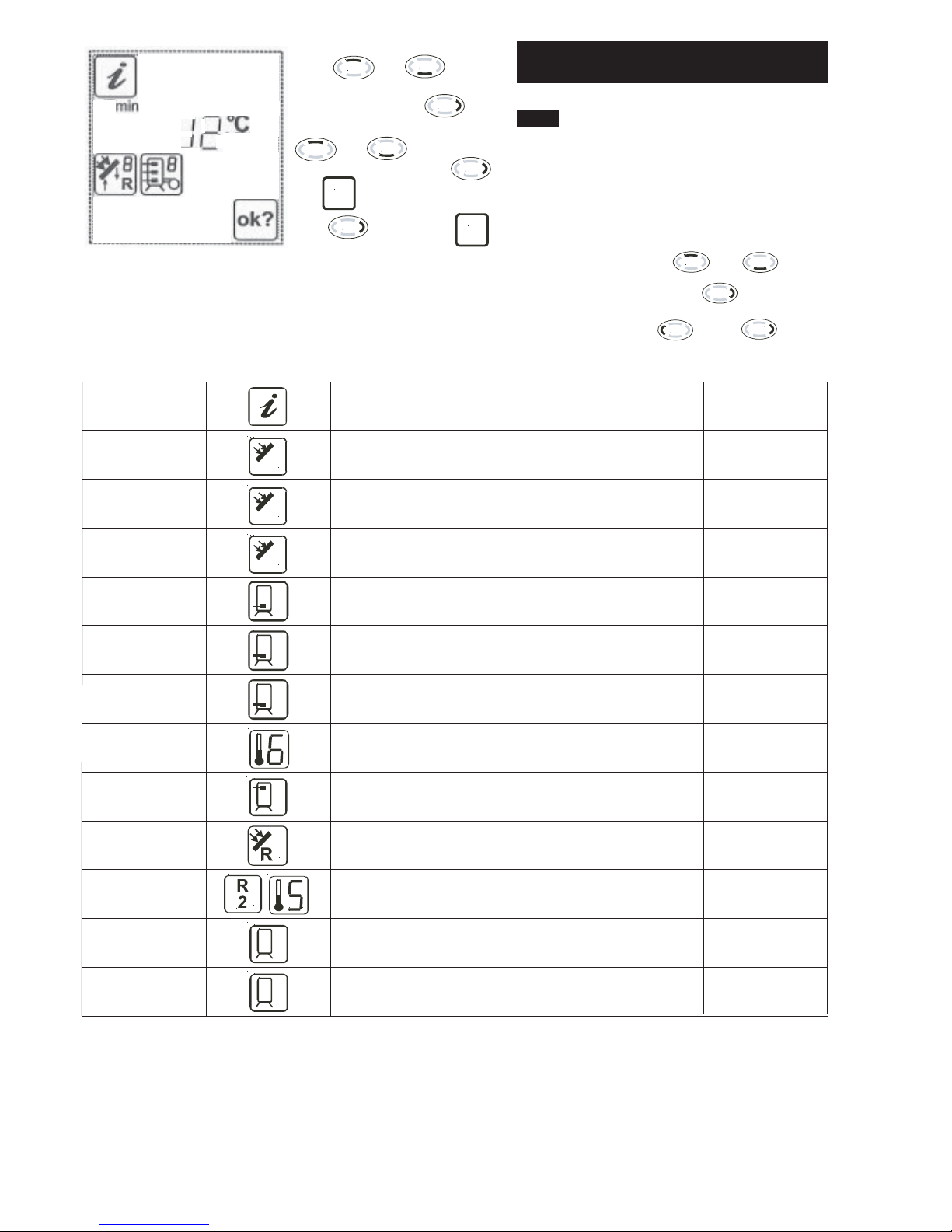
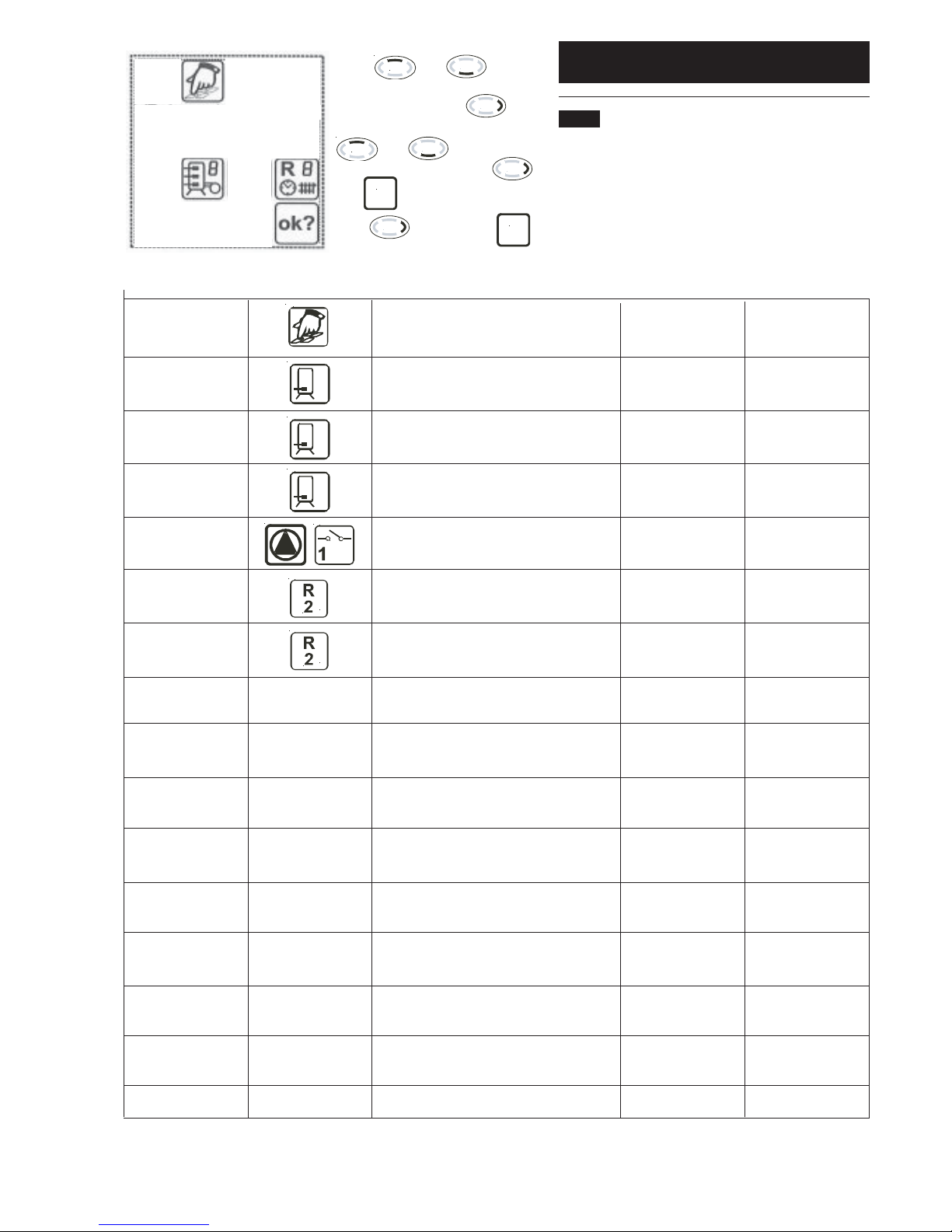
Operation of the Solar Controller
Explained the icons and their meanings displayed at the
controller.
System Malfunction
Explained what to do in the event of a system fault including
how to isolate the electrical supply or water supply.
System Maintenance
Explained the necessity for the system to receive regular
maintenance to ensure its continued safe and efficient
operation.
Literature
The Commissioning Record (see page 21 of the SolarfloTM
Commissioning, Maintenance and Servicing Guide Instructions)
should be completed and left with the user.
These instructions explain a number of the above points and
should be retained as a reminder of how to operate the
SolarfloTM water heating system.
If you are in any doubt, please ask your installer for
clarification or contact the Baxi Technical Enquiry Line,
Telephone 0844 871 1568.
2
© Baxi Heating UK Ltd 2011.All rights reserved. No part of this publication may be reproduced or
transmitted in any form or by any means, or stored in any retrieval system of any nature
(including in any database), in each case whether electronic, mechanical, recording or otherwise,
without prior written permission of the copyright owner, except for permitted fair dealing under
Copyrights, Designs and Patents Act 1988.
Applications for the copyright owner’s permission to reproduce or make other use of any part of
this publication should be made, giving any details of the proposed use to the following address:
The Company Secretary, Baxi Heating UK Ltd, Brooks House, Coventry Road,Warwick. CV34 4LL
Full acknowledgement of author and source must be given.
WARNING: Any person who does any unauthorised act in relation to a copyright work may be
liable to criminal prosecution and civil claims for damages.
© Baxi Heating UK Ltd 2011

3
2.0 Baxi Solarflo Description
2.1 Description
Your SolarfloTM system consists of several component parts that
work together to heat your domestic hot water supply either
from the power of the sun, by conventional means (by a boiler
or electric immersion heaters) or combination of both.
This combination is required because the sun’s energy is not
uniformly received throughout the year (some 70% of the UK’s
annual radiation is received over the period April to
September).The amount of sunshine hours will vary and the
proportion of direct radiation (from a clear sunny day) and
diffuse radiation (from partly cloudy or overcast skies) will also
vary. However, on average up to 60% of a dwellings annual hot
water requirement can be provided by a solar water heating
system.The balance is provided by the auxiliary heating source.
Fig 1 shows the main component parts of the Baxi Solarflo
System (unvented system).
1 Solar Collector
(Note: larger cylinders may have 2 or 3 collectors
connected)
2 Solar Pump Station
3 Solar Controller
(Note: May be mounted remotely from Pump Station)
4 Solar Expansion Vessel
5 Solar Cylinder
6 Baxi Boiler Auxiliary Heating Source
(Note: Auxiliary heating may be by immersion heaters)
7 Solar Cylinder cold water controls
(Note: May not be fitted if using a cistern fed vented
cylinder eg. Heatrae Sadia Megalife)
8 Thermostatic blending valve
9 Balanced cold water supply
Fig. 1 Unvented System Example
1
2
34
5
6
7
8
9
© Baxi Heating UK Ltd 2011
Combi Valve

3.0 System Operation
3.1 Operating Settings
Generally the operating settings of your SolarfloTM Domestic
hot water heating system will have been set up by your
installer. For the system to operate correctly and efficiently
these settings should not be altered. Section 4 details the user
controls which your installer should familiarise you with during
commissioning the system.
If in doubt contact a qualified solar installation engineer,
alteration of some settings could adversely affect the
operation of the SolarfloTM system.
As with any heating system there are certain aspects that will
require regular checking and/or maintenance. Section 6 details
what these should be. Any maintenance or servicing should
only be carried out by qualified personnel and be recorded in
the Commissioning Maintenance and Servicing Guide supplied
with the SolarfloTM.
4© Baxi Heating UK Ltd 2011

4.0 User Controls
5
© Baxi Heating UK Ltd 2011
1
2
4
35
Main Menu
Display Screen
Control Button
Scroll upwards
Scroll downwards or select required main menu
Scroll left or exit to main menu
Scroll right or select to edit function
2
4
3
5
1
4.1 Main Menu
To make the operation of the controller clear, operating and
display functions are divided into 4 main menus.
Info Indication of current measured values.
Indication of system condition.
Indication of error messages.
Indication of operating hours and
energy productivity (if installed).
Programming Changes to programmable values
(parameters).
Manual operation This menu is for the installation
engineer only.
Basic adjustment This menu is for the installation
engineer only.
It is not intended that the householder should attempt to
programme the operation of the system so various parts of the
programming menu are not reproduced here.
NOTE: Altering some settings could adversely affect the
operation of the SolarfloTM system, if in doubt contact a
qualified solar installation engineer. Alteration of functions,
not covered in this user guide will invalidate the warranty.
Each active menu is shown in the upper line of the display by its
corresponding icon.
4.2 Control Button
When in the Main Menu the control button functions are as
follows:
Item 2 - Scroll upwards- no function in this menu
Item 3 - Scroll left - moves left through the main menu
options
Item 4 - Scroll down - selects the menu option currently
flashing and gives access to the sub-
menu
Item 5 - Scroll right - moves right through the main menu
options
Once the sub-menu has been accessed, the flashing symbol
becomes static and the button functions are then as follows:
Item 2 - Scroll upwards- moves up through the available
functions of the sub-menu
Item 3 - Scroll left - return to main menu
Item 4 - Scroll down - moves down through the available
functions of the sub-menu
Item 5 - Scroll right - select to edit the function displayed.
The selected function will flash if it is
available for editing. Use 2 to increase
the required value and 4 to reduce it.
Use 5 to OK.
Diagram of Menu Options
Example Screen - Programming Menu

4.0 User Controls
6© Baxi Heating UK Ltd 2011
4.2 Menu “Info”
In this menu mode all measured values and operating states
are shown.
If the values are marked as “reset possible”, they may be reset
in the following way:
Choose the value with buttons and
Reset value by means of the button
Message “OK?” confirm with = no or = yes
Indication Description Reset possible
75ºC Indication of current collector temperature no
min. 12ºC Indication of minimum collector temperature yes
Re-settable to current temperature
max. 105ºC Indication of maximum collector temperature yes
Re-settable to current temperature
52ºC Indication of current temperature storage tank (lower) no
min. 40ºC Indication of minimum temperature storage tank (lower) yes
Re-settable to current temperature
max. 65ºC Frost protection or common measuring point yes
25ºC Indication of universal temperature measuring points (T3) no
55ºC Indication of current temperature storage tank thermostat no
60ºC Indication of current temperature collector return no
60ºC Indicates Auxiliary Heating Coil Temperature no
T6
1234 h Operating hours for charging storage tank Yes
Resettable to 0 h
927 kWh Energy productivity for storage tank Yes
Resettable to 0 kWh
Press or to scroll
up or down to the required sub function.
The icon will flash, press to
select the function. Reset by pressing
or for
increase/decrease values. Press
and appears,
press to confirm and
disappears.
ok?
ok?
Example of Screen Display

4.0 User Controls
7
© Baxi Heating UK Ltd 2011
4.3 Menu “Programming”
All adjustable parameters can be checked in this menu and, if
necessary, changed.The default factory setting will usually give
efficient and problem free operation. However Baxi recommend
the following parameters marked * must be left at the default
settings. Any change to the Baxi recommended settings will
invalidate the warranty.
Indication Description Value range Defaults
max Storage 1/2: 15..65ºC 65ºC *
65ºC Maximum temperature
dT max Storage 1/2: Hysteresis (dT on) * 3..40 K 7 K
7 K
dT min Storage 1/2: Hysteresis (dT off) * 2..35 K 3 K
3 K
min Setting the speed control of the pump 30%..100% 100%
100 100% = speed control off
min Temperature start for the function 20..90ºC 40ºC
40ºC heating
dT Hysteresis heating 1..30K 10K
10K
min Start time 1 0:00... 00:00
(1) 00:00 for the independent controller 23.59
max Stop time 1 0:00... 23:59
(1) 23:59 for the independent controller 23:59
min Start time 2 0:00... 00:00
(2) 00:00 for the independent controller 23.59
max Stop time 2 0:00... 23:59
(2) 23:59 for the independent controller 23:59
min Start time 3 0:00... 00:00
(3) 00:00 for the independent controller 23.59
max Stop time 3 0:00... 23:59
(3) 23:59 for the independent controller 23:59
min Start time 4 0:00... 00:00
(4) 00:00 for time controlled circulation 23:59
max Stop time 4 0:00... 23:59
(4) 23:59 for time controlled circulation 23:59
13:21 Clock 0:00...23.59 12:00
2
Press or to scroll
up or down to the required sub function.
The icon will flash, press to
select the function. Reset by pressing
or for
increase/decrease values. Press
and appears,
press to confirm and
disappears.
ok?
ok?
* Temperature lag between switch on and switch off

4.0 User Controls
The controller will display certain information in the event of some system faults.The following table indicates these and will aid in describing the
nature of the fault to the Service Engineer. DO NOT attempt to rectify faults yourself, contact Technical Enquires on 0844 871 1568 or a qualified
Solar water heating engineer.
Error representation on display Possible reasons
flashing
• Sensor wire broke
• Sensor defect
flashing
• Short circuit in sensor wire
• Sensor defect
• Error in pump connection
• Pump defect
• Air in the system
• Connection with flow
meter defect
• Sensor wire broken
• Sensor defect
• Go back through menu to
identify fault or contact
Technical Enquires
!
!
!
+
Circulation error: no flow
Additionally at energy
productivity measurement:
flashing
!
Status indication
Solar circulation pump Symbol revolves when solar circulation pump is on
Switch output 1 is active Appears when switch output 1 is active (on)
Switch output 2 is active Appears when switch output 2 is active (on)
Switch output 3 is active Appears when switch output 3 is active (on)
Reference to system fault Display flashes when a fault occurs in the system
Safety query for value changes which are to be stored Input value can be either
rejected or accepted
!
ok?
8© Baxi Heating UK Ltd 2011

5.0 Important Notes
9
© Baxi Heating UK Ltd 2011
If fluid or vapour is discharged from the Pressure Relief Valve
on the Solar Pump Station, switch off the power supply to the
SolarfloTM Controller and contact a qualified solar water heating
engineer.
Familiarise yourself with the controls and instructions supplied
with the Solar Cylinder and follow manufacturer’s instructions
in the event of a cylinder fault.
The pipework between the solar collector(s) and the solar
cylinder can be very hot.These pipes should have been
insulated by the installer.This is high temperature insulation. In
the event of damage contact Technical Enquiries.
If the electrical supply for the Solar domestic hot water heating
system is interrupted it will not operate. However, programme
settings are stored by the controller and should not need
resetting when power is restored.
The SolarfloTM Controller may have been integrrrated with the
auxiliary heating controls to optimise the solar gain from the
system and minimise the use of the auxiliary heat source. Your
installer should explain how the system will function in this
event.The Solar Controller will not control the space (central)
heating system, separate controls are necessary for this
function. Refer to the instructions supplied with any separate
auxiliary controls for details of their correct setting.

6.0 Servicing and Maintenance
10 © Baxi Heating UK Ltd 2011
To ensure the continued safe and efficient operation of your
SolarfloTM water heating system it is essential that it is checked
and serviced annually by an approved qualified solar engineer.
The Servicing and Maintenance Record in the Commissioning,
Maintenance & Servicing Guide must be completed by the
solar engineer after each annual service. In the event of a
warranty claim it will be necessary to show that the routine
annual maintenance has been carried out and the Servicing
and Maintenance Record has been kept up to date.
Additionally, every two years the concentration of the solar
thermal transfer fluid should be checked and if necessary
replaced or replenished. Failure to maintain the system may
invalidate your warranty.
For warranty Terms and Conditions see Commissioning,
Maintenance & Servicing Guide

7.0 Notes
11
© Baxi Heating UK Ltd 2011

All descriptions and illustrations provided in this leaflet have been carefully prepared but
we reserve the right to make changes and improvements in our products which may affect
the accuracy of the information contained in this leaflet. All goods are sold subject to our
standard Conditions of Sale which are available on request.
Comp No 5130228 - Issue 2 - 3/11
BAXI
A Trading Division of Baxi Heating UK Ltd (3879156),
Brooks House, Coventry Road,Warwick. CV34 4LL
Technical Enquiries 0844 871 1568
Our contact centre is open Monday to Friday 8am to 6pm,
Weekends and Bank Holidays 8.30am to 2pm.
We are closed Christmas Day and New Years Day.
Website www.baxi.co.uk
e&oe
© Baxi Heating UK Ltd 2011
Other manuals for Solarflo
5
Table of contents
Other Baxi Solar Panel manuals