Selectronic 2000 EVO1 User manual

EN HEATING CONTROLLER UNIT • Installation Manual
Important Notice.......................................................... 3
Type ariants...............................................................3
Frontpanel...................................................................4
Control Board..............................................................4
Connecting, Power Up.................................................5
Software Settings........................................................8
Software - Main Screen...............................................8
Software - Main Menu..................................................9
Software - Zone Menu...............................................12
List of Parameters......................................................15
Technical data............................................................15
Index.........................................................................16

E O-SZUTM_A5B010AEN
Fig. 1.
Fig. 2.
Fig. 3.

EN
IMPORTANT NOTICE
Attention! Improper installation or operation shall lead to serious accidents and damages! In order to perform proper installation and operation, all and any instructions shall
absolutely be respected!
Before putting into operation, please read these Installation Manual carefully!
Any installation works, connections and settings, repairs and servicing of electronic commands discussed here shall only be performed by electricians qualified for heating
techniques under strict respect of safety and security rules in force or detailed here.
The mechanic shall be liable to organise training for the end user (both orally and in writing) about the operation of equipment, on possible sources of risk and on routine checks
to avoid eventual errors.
It is strictly prohibited to connect and set up electronic equipment under voltage because of risk of electric shock!
Electronic command is highly sensible to humidity, vapours and contaminations, which might even cause lasting malfunctions, too. The command is equipped with rubber stuffing
boxes of IP 67 protection, which, in case of intended use, prevent intrusion of humidity, vapours or contaminations to the command.
Command panels located in the top and bottom of box are linked to each other by a multicore cable. You shall not leave the box cover hanging on this cable in any case! When
installing, you shall provide a support to the box cover or have it removed by disconnecting the easily dismantling line terminals!
Improper putting into operation of product might cause a serious, eventually incurable error either in command or in sensors or in other complementary parts or in devices
operated (radiator, fan etc.).
The product is particularly ESD sensible (sensible for discharges caused by electro-static charge), for this reason, before touching the product, you shall proceed to electro-static
discharging in any case.
Acknowledgement operations (deleting error messages of burner or radiator) can only be performed if visibility onto equipment is fully ensured, a workmanlike inspection
completed professionally, nobody staying near to equipment and by putting the equipment into operation, no personal injury or material or property damage can occur.
Warning! We decline our liability for damages originating from non-respect of safety, installation or other instructions listed in these ’Instructions of Installation’ or of safety and
security prescriptions actually in force! Non-compliance with these clauses might involve the expiry of guarantee!
The product may not be treated as household waste. Instead it shall be handed over to the applicable collection point. By ensuring of this product is disposed correctly, you
will help prevent potential negative consequences for the environment and human health. Recycling materials helps preserve resources of the earth.
TYPE VARIANTS
EVO1 heating controller unit for one zone
▪ FUNCTIONS:
▫ industrial temperature controller unit for several types of burners
▫ controlling of 1 zone
▫ easy to set up & work with via informative LCD and useful keyboard
▫ heating expenses stored for last 4 years in monthly split
▫ several acces levels to avoid unintentional adjustments
▪ INPUTS:
▫ 1 x emergency stop input(NC)
▫ 1 x fan safety relay input(NC)
▫ 1 x remote controller input(customizable)
▫ 2 x inner temperature sensor input(averaged)
▫ 1 x outter temperature sensor input
▪ OUTPUTS:
▫ 1 x fan output
▫ 1 x 2-staged burner output(with reset output & error signal input)
▫ 1 x global error message output
EVO2 heating controller unit for two zones
▪ FUNCTIONS:
▫ industrial temperature controller unit for several types of burners
▫ controlling of 2 zones
▫ easy to set up & work with via informative LCD and useful keyboard
▫ heating expenses stored for last 4 years in monthly split
▫ several acces levels to avoid unintentional adjustments
▪ INPUTS:
▫ 1 x emergency stop input(NC)
▫ 2 x fan safety relay input(NC)
▫ 2 x remote controller input(customizable)
▫ 2 x inner temperature sensor input
▫ 1 x outter temperature sensor input
▪ OUTPUTS:
▫ 2 x fan output
▫ 2 x 2-staged burner output(with reset output & error signal input)
▫ 1 x global error message output
EVO3 heating controller unit for three zones
▪ FUNCTIONS:
▫ industrial temperature controller unit for several types of burners
▫ controlling of 3 zones
▫ easy to set up & work with via informative LCD and useful keyboard
▫ heating expenses stored for last 4 years in monthly split
▫ several acces levels to avoid unintentional adjustments
▪ INPUTS:
▫ 1 x emergency stop input(NC)
▫ 3 x fan safety relay input(NC)
▫ 3 x remote controller input(customizable)
▫ 3 x inner temperature sensor input
▫ 1 x outter temperature sensor input
▪ OUTPUTS:
▫ 3 x fan output
▫ 3 x 1-staged burner output(with reset output & error signal input)
▫ 1 x global error message output
EVO4 heating controller unit for four zones
▪ FUNCTIONS:
▫ industrial temperature controller unit for several types of burners
▫ controlling of 4 zones
▫ easy to set up & work with via informative LCD and useful keyboard
▫ heating expenses stored for last 4 years in monthly split
▫ several acces levels to avoid unintentional adjustments
▪ INPUTS:
▫ 1 x emergency stop input(NC)
▫ 4 x fan safety relay input(NC)
▫ 4 x remote controller input(customizable)
▫ 4 x inner temperature sensor input
▫ 1 x outter temperature sensor input
▪ OUTPUTS:
▫ 4 x fan output
▫ 4 x 1-staged burner output(with reset output & error signal input)
▫ 1 x global error message output
3

EN
FRONTPANEL
The unit includes the operating organs shown in figure (Fig. 1).
The operation shall be performed in the manner used by mobile phones: communication can be established with the device, navigation performed in menu system, setting
performed on basis of information displayed on the screen through function keys, direction keys, OK-button and Esc-button.
Esc-button can be used at any point of menu system to prevent unintentional or erroneous data modification.
1 - DISPLAY
colour display with backlight to show or visualise miscellaneous status information, parameters settled or any other function/information
2 - FUNCTION KEYS
they have no permanent function, this is the text displayed on screen informing about their actual role (like for mobile phones)
3 - DIRECTION KEYS
they enable navigation within information, menus or parameter settings displayed on the screen (like for mobile phones)
4 - OK BUTTON
its main task is confirmation of information, or parameter settings
5 - ESC BUTTON
its main task is rejecting information, or parameter settings by returning to main screen
CONTROL BOARD
The panel is composed of control, signalling and connecting units shown in figure (Fig. 4A, 4B, 4C, 4D).
Wire connections can easily be performed by using dismantling terminal blocks and terminal block functions marked on panel by pictures if possible.
You shall not leave the box cover hanging on the flat multicore cable in any case! When installing, you shall provide a support to the box cover or have it removed by
disconnecting the easily dismantling line terminals!
1 - TERMINAL BLOCKS
see their detailed description and connections in next chapter
2 - RELAY LEDS
signalling the status of corresponding relay
Lighting: the relay is energised
Not lighting: the relay is de-energised
3 - BATTERY
it serves exclusively for power supply of internal clock permanently on even in case of power error, any other saved function / parameter setting will safely be
saved without battery and power supply, too
Concerning battery type, see technical data.
4 - FLATCABLE CONNECTOR
connector for frontpanel's flatcable
You shall not leave the box cover hanging on the flat multicore cable in any case!
5 - SUPPLY LED
LED signalling the presence of low voltage supply
6 - B1 FUSE
fuse of low voltage part, for its value see the technical data
he LED lights in case of error of fuse.
7 - PC KEYBOARD
connecting of a standard PC keyboard by PS2 connection, which enables control to be set even more easily
8 - AUX.CONNECTOR
serves for connecting auxiliary panels to the control unit
4
Fig. 4A: Control Board - EVO1
Fig. 4B: Control Board - EVO2

EN
CONNECTING, POWER UP
Perform connecting of control unit according to the figure (Fig. 5A, 5B, 5C, 5D) and instructions detailed hereunder.
▪ Do respect safety and security prescriptions! All interventions shall be performed in voltage-free status!
▪ Installation of box:
▫ Locate the box at eye level, if possible, to enable good visibility of display and buttons could easily be operated
▫ Before setup, remove control panel from box in order to prevent damages during drilling and fixation
▫ You shall not leave the box cover hanging on the flat multicore cable in any case! When installing, you shall provide a support to the box cover or have it removed by
disconnecting the easily dismantling line terminals!
▪ Connecting cables:
▫ Regarding to cable sizes see technical data
▫ Insert cables needed into the box through cable glands, from below, if possible
▪ Preparation of connections: terminal blocks shall be connected in voltage-free status, as shown in figure (Fig. 5A, 5B, 5C, 5D), in any case, you shall respect the maximum
loadability restlessly, as indicated in technical data
▫ Power s pply inp t (230V): take care of correct order of phase and neutral wires when connecting power supply and other equipments
▫ Fan o tp ts (230V):
◦ at fan terminals neutral is permanently present; phase shall be switched on by fan-relay
◦ if the fan to be connected to output having a higher power consumption than indicated among technical data or being of 380 type, use a 230 relay for
switching, which can directly be connected to the place of fan
▫ B rner o tp ts (230V): depending on burner type, output shall not be connected necessarily to terminal block points marked by ’Stage2’, ’Reset’ and ’Error’, as the
unit being operational without them, only some functions cannot be accessed
◦ ’Neutral’ output: means the neutral wire of burner; neutral shall permanently be present, not switched
◦ ’Stage1’ output: phase output switched by Stage1-relay
· in case of a single stage burner or radiator, the phase wire of burner/radiator shall be connected here
· in case of a double stage burner or radiator, the phase wire of first stage of burner/radiator shall be connected here
◦ ’Stage2’ output: phase output switched by Stage2-relay
· in case of a single stage burner or radiator, it is not in use (shall be left free)
· in case of a double stage burner or radiator, the phase wire of second stage of burner/radiator shall be connected here
◦ ’Reset’ output: neutral output switched by the reset-relay, which terminal block shall receive zero potential when burner/radiator confirmed (when not in
use, it shall be left free)
he reset output can be activated when zone error confirmed.
◦ ’Error’ input: 230 error message input for burner/radiator, to which phase shall be switched by burner/radiator when its function failed (when not in use, it
shall be left free)
Error signal given to input shall only serve for information to control unit, its function not being influenced thereby (a zone error symbol will appear
which can be confirmed)
▫ Error message o tp t: general error message of control unit (potential-free NO), which shall be activated synchronously with warning error symbol appeared on
screen: if error signalled by the symbol, the complementary relay will be energised and terminal block points of ’Complementary output’ shall be short-circuited
▫ Emergency stop inp t: this is a low voltage NC (normally closed) input serving for connecting emergency stop button: if the button pressed, the input shall be cut and
the functions of both heating radiator and fan shall be disabled by control software
▫ Fan thermal-relay inp ts: this is a low voltage NC (normally closed) input serving for connecting breaker contacts of fan thermal relay switch: if fan function failed
and overcurrent being present, the thermal relay input contact shall be cut and the functions of both heating radiator and fan shall be disabled by control software
5
Fig. 4D: Control Board - EVO4
Fig. 4C: Control Board - EVO3

EN
▫ Remote control inp ts: this is a low voltage input having impact only in ’Remote control mode’ of control unit: in this mode, opening or closing contacts put to this
input shall switch the heating radiator (it can be set in software, how)
▫ Zone internal temperat re sensor inp ts: low voltage analogous inputs, which TEMP-IN or TEMP-OUT type sensors can be connected to
◦ By using TEMP-IN sensor, the ’Overtime heating’ mode can be activated, by which the operator can request one supplementary hour of heating after the
heating unit switched off
◦ By using TEMP-OUT sensor, this mode is disabled, and cannot be activated
◦ Inputs ’Inner1’ and ’Inner2’:
· when using one internal sensor, there is no importance, which input being connected to
· when using two internal sensors, an average temperature will be reckoned from measured data
· ’Overtime heating’ mode can be activated from both inputs (by using both ’temp-in’-s)
▫ External temperat re sensor inp t: low voltage analogous input, which TEMP-OUT type sensor can be connected to
◦ it is not absolutely necessary to use an external heat sensor, but the software shall be set in any case, whether used or not
◦ by using external sensor, you will be given the possibility to use ’Optimisation heating-up’ mode
▪ Connection of auxiliary panel:
▫ You shall exclusively use auxiliary panels which being compatible with E O control unit, information thereof can be obtained in the description of complementary panel
▫ Insert complementary panel into 10 pin serial connector of control unit as shown in figure (Fig. 2.), and check then correctness of connection
▪ Power up the unit:
▫ Insert battery into battery holder of control panel
▫ Connect serial connector of flat multicore cable of box cover into lower control panel until fixation pins snapped into their resp. position (the connector can only be
assembled in one single position, no reverse connection is possible)
▫ Check all connections and contacts once again
▫ Ensure that no one is staying near to control unit and to connected equipment and by putting the equipment into operation, no personal injury or material or property
damage can occur
▫ Put control unit onto power supply
▫ Controls 0mark their waking up by loud beep
▪ Performing/inspection of parameter settings:
▫ Control unit is delivered with preset factory parameters, these values shall be checked or corrected for adjusting to local site characteristics
▫ Carry out software settings or fine tunings according to the chapter ’Software settings’
6
Fig. 5A: Connection of erminal Blocks - EVO1
Fig. 5B: Connection of erminal Blocks - EVO2

EN
7
Fig. 5C: Connection of erminal Blocks - EVO3
Fig. 5D: Connection of erminal Blocks - EVO4

EN
SOFTWARE SETTINGS
A cornerstone of control unit software is simplicity, enabling fluent trial run, transparency of settings and smooth operation. Its functions and operation are similar to those of
popular mobile phones.
The software consists of a main screen – where details of heating zone status information can be gathered from – and of two simple menu systems to be accessed from hits main
screen.
In one of these menu systems – the main menu –, we can perform global settings (e.g. of date, time, languages can be set etc.), which are independent from zones and are of
general application.
The other menu system – the zone menu –, serves to perform settings closely linked to zone (e.g. zone operating mode, zone time program, zone temperatures etc.).
SOFTWARE - MAIN SCREEN
The main screen is an information screen aiming at furnishing detailed information about the status of actual heating zone or of other parameters, its structure being shown in the
figure (Fig. 3.).
Both menu systems can be accessed from main screen, the main menu and the zone menu, too.
1 - ZONE NAME
the heating zone actually selected, we can be informed thereof
2 - OPERATING MODE
actual operating mode of zone
Symbol 'A': control unit is in automatic mode
automatic mode, in which the control unit automatically changes between daytime and night time and holiday time modes, and, when necessary, starts
optimisation heating up or activate overtime heating with the push-button of internal thermal sensor
Symbol 'M': control unit is in manual mode
means manual operating mode, in which the control unit maintains a fixed operating mode selected by us
3 - DETAILS OF OPRATING MODE
In case of automatic mode: as a rule, the graphic daily time schedule being displayed, except for holidays, during both optimisation heating up and overtime heating up,
the remaining duration will be displayed
In case of manual mode: the manual mode type selected will be displayed
4 - INNER TEMPERATURE
the temperature measured within zone will be displayed
5 - OUTTER TEMPERATURE
displays the temperature measured by outside heat sensor of system (if mounted)
6 - KEY SYMBOL
displays actual access level, which defines the nature of modifications and settings to be performed within system through software (about authorisation list
you can be informed in Chapter ’Accessibility levels’)
No symbol: means a basic authorisation of accessibility (allows no changes in system)
Key1 symbol: operator’s accessibility level (medium level enabling some settings)
Key2 symbol: officer’s accessibility level (medium level enabling many settings)
Key3 symbol: service accessibility level (highest level enabling all settings)
7 - GENERAL EMERGENCY SYMBOL
informs about any error observed within heating system
No symbol: there is no error either in zones or in system
Red symbol: there is some error in one of zones, or in certain parts of system (details of error can be learned from ’Error info’)
8 - DATE,TIME
the actual time/date will be displayed
9 - BURNER SYMBOL
shows the functional status of zone radiator (in accordance with stage1 and stage2-relays)
Gray symbol: radiator is not functioning
Green symbol with one wave: radiator is functioning (in case of double stage burner/radiator only one stage is functioning)
Green symbol with two waves: radiator is functioning, both stages are switched on
10 - FAN SYMBOL
shows the functional status of zone fan (in accordance with fan relay)
Gray symbol: fan is not functioning
Green symbol: fan is functioning
11 - ZONE EMERGENCY SYMBOL
informs about a error in the inside of zone
Gray symbol: there is no error within zone
Red symbol: there is some error within zone (details of error can be learned from ’Error info’)
8

EN
SOFTWARE - MAIN MENU
In main menu to be accessed from information main screen we can perform general settings relating to control unit and heating system (e.g. setting date, time, language etc.),
which are not in close relationship with individual heating zones.
Zone settings can be performed from zone menu according to Chapter ’Zone menu’.
The figure shows the structure of main menu system (Fig. 6.) and accessibility of each setting. The description of numbered menu points can be found below figure.
9
Fig. 6: Main Menu System - page1

EN
1 - DATE SETTING
setting actual date
2 - DATE FORMAT
setting date format according to territorial location
3 - DATE SEPARATOR
setting date separation character
4 - TIME SETTING
setting actual time in 24 hours’ format
5 - TIME CORRECTION
enables fine tuning of internal clock of controller by this setting. If the clock is ahead or behind, the correction of daily difference measured in seconds
shall be set here
6 - SUMMER/WINTER TIME
setting DST mode
Automatical: in this mode, time will automatically be adjusted at the time of official time change
Manual: in this case, the operator shall perform DST in ’Time Setting’ menu
7 - CURRENCY
setting currency to display zone costs
8 - ENERGY COST
unit price of energy calculated from fuel price and specific heat [EUR/kWh]
Calculation for oil: (unit price of oil [EUR/kg] / caloric power [MJ/kg]) * 3.6 [MJ/kWh]
Calculation for gas: (unit price of gas [EUR/m3] / caloric power [MJ/m3]) * 3.6 [MJ/kWh]
9 - LANGUAGE SELECTION
setting of controller language
10 - PC KEYBOARD
setting the layout of PC keyboard to be connected
11 - KEYBOARD BEEP
switching keyboard beeps on/off when touched
12 - CONTROLLER INFO
displays information relating to putting into operation and servicing of heating system and to controller itself
Service constact: displays contact data of servicing company
Next servicing: displays next date of service/supervision suggested by service company
Installation date: displays the date of putting into operation of heating system
10
Fig. 6: Main Menu System - page2

EN
13 - PASSWORDS
lists or enables modification of passwords to each access level (operator, officer, service)
Worker passoword: displays contact data of servicing company
Boss password: displays next date of service/supervision suggested by service company
Sercvice password: displays the date of putting into operation of heating system
14 - SER ICE CONTACT
displays contact data of servicing company (to be consulted by user under ’Controller info’)
15 - INSTALLATION DATE
for entering the date of putting into operation of heating system (to be consulted by user under ’Controller info’)
16 - NEXT SER ICING DATE
for entering next date of servicing or inspection suggested by servicing company
17 - NEXT SER ICING NOTIFICATION
alert signal selection to notify the user to have the necessary servicing or inspection carried out
No notofication: there will be no alert when service date reached
Message notification: when service time reached, an alert box will be opened periodically to alert to service needed
Message&sound notification: when service time reached, there is an acoustic sound together with opening alert box
18 - OUTTER SENSOR
setting whether an external thermal sensor connected to system or not
19 - OUTTER SENSOR CORRECTION
correction value for outter sensor that is added to its measured value
20 - ERROR NOTIFICATION
warning and signalling an error observed in heating system
Blinking icon only: error message by blinking alert icon in display
Blinking icon+sound: error message by blinking alert icon and sound
21 - FUNCTION 101
setting activation time for function „101” or disabling function
22 - RESET TO DEFAULTS
deleting all parameters and settings of controller and resetting them to default factory status
23 - LOGIN
login into controller by entering password of access level, to enable access to locked menu items, as applicable
11

EN
SOFTWARE - ZONE MENU
In the zone menu accessible from information main screen, the settings relating to individual heating zones can be carried out (e.g. actual operating mode, temperature settings
for daytime, night time operation, burner data etc.). As a particularity of zone menu, it is possible to simply alternate between zones without leaving menu, which enables
significantly quicker setting of zones or inspection zone settings.
Miscellaneous other general settings, which are relating to controller unit or to the whole of heating system, can be carried out in main menu according to Chapter ’Main menu’.
The structure of zone menu system can be seen in figure (Fig. 7.), together with accessibility of individual settings. The description of numbered menu points of figure can be
found below the figure.
12
Fig. 7: Zone Menu System -page1

EN
1 - AUTOMATIC MODE
selection of full automatically controlled zone operation, during which the following temperatures maintained by the system
▫ Daytime and night time temperatures basically alternating by controller according to weekly time schedule
▫ Holiday periods are taken into consideration, during which holiday temperature is permanently maintained
▫ When temperature optimisation function set, night time temperature can earlier be changed against daytime temperature than set in weekly time program (optimised
heating up mode), so as to reach daytime temperature in desired time
▫ In night time mode, one hour of daytime temperature period can be requested by actuating push button of internal heat sensor (overtime heating mode)
13
Fig. 7: Zone Menu System - page2

EN
2 - MANUAL MODE
changeover of zone concerned to manual mode, during which the manual mode selected will be constantly maintained
Continuous day temp: permanently maintained daytime temperature mode selected
Continuous night temp: permanently maintained nighttime temperature mode selected
Custom temp: permanently maintained custom set temperature mode selected
Antifrost: permanently maintained frost protection temperature mode selected
Remote mode: selecting remote control mode, during which the signal sent to remote control input (open/close contact) turns burner/radiator on or off (to
correct operation set operational logic of remote control)
Chimney-sweep: selects timed mode to measure burners/radiators, during which burners/radiators will permanently be turned on
3 - ZONE TURN OFF
turns off the heating of given zone
4 - WEEKLY TIME PROGRAM
setting weekly time program of zone in automatic mode in a simple, transparent graphical manner. On 24 hours’ continuum of numbers, blue
colour means night time temperature, red corresponds to daytime temperature. Here you can consult, modify, delete or create red domains to develop daily temperature
programs, as required.
Change: modification of actual red domain period (red domains will automatically be blended, if overlapping occurred)
Add: creates new red domain for actual day
Delete time interval: deletes actual red domain
Delete whole day: deletes all red domains for actual day
Delete whole week: deletes all red domains for all days of zone
Copy day to day: copies actual daily time program to another day within zone, by overwriting (e.g. copy Monday of Zone1 to uesday of Zone1)
Copy day to zone: copies actual daily time program to the same day of another zone, by overwriting (e.g. copy Monday of Zone1 to Monday of Zone2)
Copy week to zone: copies whole weekly time program to another zone, by overwriting (e.g. copy all days Zone1 into Zone2)
5 - HOLIDAYS
setting holiday periods in automatic mode of zone. During periods set, the holiday temperature will be maintained in automatic mode.
6 - TEMPERATURES
setting temperatures
Day temp: setting daytime temperature to be used in automatic mode and as perm. daytime temperature in manual mode
Night temp: setting nighttime temperature to be used in automatic mode and as perm. nighttime temperature in manual mode
Holiday temp: setting holiday time temperature to be used in automatic mode during holiday periods
Antifrost temp: setting defrosting temperature to be used in frost protecting manual mode (neither daytime, nor nighttime nor holiday temperatures will be
allowed to be lower than the temperature set here)
Remote min.temp: setting minimal zone temperature of remote mode; below this temperature level the heating forced to start unconditionally
Remote max.temp: setting maximal zone temperature of remote mode; above this temperature level the heating forced to stop unconditionally
7 - TEMPERATURE OPTIMIZATION
enabling temperature optimisation function, causing that in automatic mode the change between nighttime and daytime modes will be
performed earlier than set in weekly time schedule, so as to reach daily temperature of zone to desired time (the temperature optimisation function can only be used
when external heat sensor installed within system)
8 - INNER-SENSOR CORRECTION
setting temperature correction caused by the location where internal heat sensor of zone installed; the value set here shall be
deducted/added from/to real temperature measured by heat sensor
9 - HYSTERESIS
setting switching hysteresis of burner/radiator
1st stage hysteresis: switching hysteresis of stage1. of burner/radiator (see fig. 8.)
2nd stage delta-T: switching hysteresis of stage2. of burner/radiator (see fig. 8.)
10 - TIMINGS
settings of turning ons and offs of burner/radiator
Burner min.worktime: sets minimum operating time of burner (see fig. 8.)
2nd stage delay: sets delayed start of stage 2. after startup of burner (see fig. 8.)
entilator on delaying: sets delayed start of fan after startup of burner (see fig. 8.)
entilator off delaying: setting delayed stop of fan after shut-off of burner (see fig. 8.)
entilator min.stoptime: setting minimal idle time of fan after shut-off (see fig. 8.)
11 - REMOTE WORKING LOGIC
setting contact definition set to remote control input
NC=heat: short-circuiting of remote control input turns heating on, removal of input short-circuit turns heating off in remote controlled manual mode
NC=no heat: short-circuiting of remote control input turns heating off, removal of input short-circuit turns heating on in remote controlled manual mode
12 - BURNER TYPE
setting stage numbers of burner
One staged: means one-stage burner/radiator
Two staged: means double stage burner/radiator (burner starts up by starting stage 1, then after a delay, the second stage will also be started)
13 - BURNER RESET MODE
setting ACK method of burner/radiator
Send reset signal: the controller sends a reset-signal to burner for a short time (can be used if there is a reset nput connected to burner)
1 minute powerloss: the controller switches off burner for a short time, then, if necessary restarts it (can be used in the case if there is no reset input on burner or it
is disposing of but not being connected to)
14 - BURNER POWER
setting burner power (used to consumption data calculation)
1st stage: means the power of burner for one-stage burner and that of first stage for double stage burner
Both stages: total power of double stage burner (shall only be given in case of double stage burner)
15 - ZONE DESCRIPTION
setting zone designation (in main screen will be added to zone number, if indicated)
16 - ZONE BUSMODULE#
used only with bus system
17 - TOTAL WORKING HOURS
display of total operating time of burner/radiator of zone (at double stage burner in brackets the number of operating hours in double stage
mode)
18 - PARTIAL WORKING HOURS
display of operating time since last resetting of burner/radiator of zone (the partly counter is similar to total operating hours’ meter, but this
one can be used as partly counter which can be reset)
19 - PARTIAL COSTS
fuel consumption costs of zone since last resetting (a correct value can only be expected if following parameters correctly set: currency, energy costs,
burner type, burner power)
20 - YEARLY COSTS
display of fuel consumption costs of zone since last years saved by the controller (a correct value can only be expected if following parameters correctly
set: currency, burner type, burner power and energy costs monthly readjusted)
21 - MONTHLY COSTS
display of monthly costs of fuel consumption of zone since last years saved by the controller (a correct value can only be expected if following
parameters correctly set: currency, burner type, burner power and energy costs monthly readjusted)
14

EN
LIST OF PARAMETERS
Symbol Description of parameter Range of val es Meas. nit
Min. Max.
1 Energy unit price 0.01 325.00 [currency unit/kWh]
2 TdDaytime temperature 8.00 30.00 [°C]
3 TnNighttime temperature 3.00 30.00 [°C]
4 Holiday time temperature 3.00 30.00 [°C]
5 Frost prevention temperature 0.00 10.00 [°C]
6 Individually set temperature in manual mode 3.00 30.00 [°C]
7 Correction of inner heat sensor -5.00 5.00 [°C]
8 Correction of outter heat sensor -5.00 5.00 [°C]
9 Timing of turn off in sweeper mode 5.00 60.00 [min]
10 Th1 Hysteresis of burner in stage 1. 0.20 2.00 [°C]
11 Th2 Delta-T of burner in stage 2. 0.10 15.00 [°C]
12 tbonmin Minimum operating time of burner 60.00 600.00 [sec]
13 ts2delay Delay of burner stage 2. 10.00 600.00 [sec]
14 tvondelay Delay time of fan start 0.00 10.00 [sec]
15 tvoffdelay Delay time of fan shut-off 0.00 20.00 [min]
16 tvoffmin Minimal idle time of fan 10.00 600.00 [sec]
17 Burner power in stage 1. 0.50 1000.00 [kW]
18 Total burner power 0.50 1000.00 [kW]
19 Correction of internal clock -22.20 22.20 [sec/day]
able 1: List of Parameters
TECHNICAL DATA
Description of product: EVO1 heating controller electronic unit
Mains supply: 230 ac 50Hz
Max. loadability of fan relay output: 16A(ohmic) 6A(inductive) 230 ac
Max. loadability of other relay outputs: 10A (ohmic) 230 ac
Power supply cable size: 3x1.5mm2
Fan cable size: 3x1.5mm2
Burner cable size: 5x1.5mm2
Sensors cable size: UTP ~0.5mm2
Own power consumption of controller unit: max. 4W
Fuse type(B1): T250mA (250V 5x20 glass tube slow fuses)
Maximal domain of operating temperature: -20..+40°C
Box protection: IP65
able 2: echnical Data
15
Fig. 8.: ime Diagram

EN
INDEX
F nction Men
2nd stage delay Zonemenu(10) → Settings → Timings → 2nd stage delay
2nd stage delta-T Zonemenu(9) → Settings → Hysteresis → 2nd stage delta-T
Antifrost Zonemenu(2) → Operating mode → Manual mode → Antifrost
Antifrost temp. Zonemenu(6) → Settings → Temperatures → Antifrost temp.
Automatic mode Zonemenu(1) → Operating mode → Automatic mode
Boss password Mainmenu(13) → Service menu → Passwords → Boss password
Burner min.worktime Zonemenu(10) → Settings → Timings → Burner min.worktime
Burner power Zonemenu(14) → Settings → Burner details → Burner power
Burner reset mode Zonemenu(13) → Settings → Burner details → Burner reset mode
Burner type Zonemenu(12) → Settings → Burner details → Burner type
Chimney-sweep Zonemenu(2) → Operating mode → Manual mode → Chimney-sweep
Continuous day temp. Zonemenu(2) → Operating mode → Manual mode → Continuous day temp.
Continuous night temp. Zonemenu(2) → Operating mode → Manual mode → Continuous night temp.
Controller info Mainmenu(12) → Controller info
Currency Mainmenu(7) → Settings → Costs → Currency
Custom temp. Zonemenu(2) → Operating mode → Manual mode → Custom temp.
Daily program Zonemenu(4) → Time program → Weekly time program → Daily program
Date format Mainmenu(2) → Settings → Date and time → Date → Date format
Date separator Mainmenu(3) → Settings → Date and time → Date → Date separator
Date setting Mainmenu(1) → Settings → Date and time → Date → Date setting
Day temp. Zonemenu(6) → Settings → Temperatures → Day temp.
Energy cost Mainmenu(8) → Settings → Costs → Energy cost
Error notification Mainmenu(20) → Service menu → Misc. settings → Error notification
Function-101 Mainmenu(21) → Service menu → Misc. settings → Function-101
Holiday temp. Zonemenu(6) → Settings → Temperatures → Holiday temp.
Holidays Zonemenu(5) → Time program → Holidays
Hysteresis Zonemenu(9) → Settings → Hysteresis → Hysteresis
Inner-sensor correction Zonemenu(8) → Settings → Temperatures → Inner-sensor correction
Installation date Mainmenu(15) → Service menu → Servicing datas → Installation date
Keyboard beep Mainmenu(11) → Settings → Language & keyboard → Keyboard beep
Language selection Mainmenu(9) → Settings → Language & keyboard → Language selection
Login Mainmenu(23) → Login
Monthly costs Zonemenu(21) → Zone info → Costs → Monthly costs
Night temp. Zonemenu(6) → Settings → Temperatures → Night temp.
Notification Mainmenu(17) → Service menu → Servicing datas → Next servicing → Notification
Outter sensor Mainmenu(18) → Service menu → Misc. settings → Outter sensor
Outter-sensor correction Mainmenu(19) → Service menu → Misc. settings → Outter-sensor correction
Partial costs Zonemenu(19) → Zone info → Costs → Partial costs
Partial hours Zonemenu(18) → Zone info → Working hours → Partial hours
PC keyboard Mainmenu(10) → Settings → Language & keyboard → PC keyboard
Remote max. Zonemenu(6) → Settings → Temperatures → Remote max.
Remote min. Zonemenu(6) → Settings → Temperatures → Remote min.
Remote mode Zonemenu(2) → Operating mode → Manual mode → Remote mode
Reset to defaults Mainmenu(22) → Service menu → Reset to defaults
Service contact Mainmenu(14) → Service menu → Servicing datas → Service contact
Service password Mainmenu(13) → Service menu → Passwords → Service password
Servicing date Mainmenu(16) → Service menu → Servicing datas → Next servicing → Servicing date
Summer/winter time Mainmenu(6) → Settings → Date and time → Time → Summer/winter time
Temp. optimization Zonemenu(7) → Settings → Temperatures → Temp. optimization
Time correction Mainmenu(5) → Settings → Date and time → Time → Time correction
Time setting Mainmenu(4) → Settings → Date and time → Time → Time setting
enti.min. stoptime Zonemenu(10) → Settings → Timings → enti.min. stoptime
entilator off delaying Zonemenu(10) → Settings → Timings → entilator off delaying
entilator on delaying Zonemenu(10) → Settings → Timings → entilator on delaying
Weekly time program Zonemenu(4) → Time program → Weekly time program
Worker password Mainmenu(13) → Service menu → Passwords → Worker password
Working hours Zonemenu(17) → Zone info → Working hours → Total
Working logic Zonemenu(11) → Settings → Remote → Working logic
Yearly costs Zonemenu(20) → Zone info → Costs → Yearly costs
Zone busmodule# Zonemenu(16) → Settings → Zone details → Zone busmodule#
Zone description Zonemenu(15) → Settings → Zone details → Zone description
Zone turn off Zonemenu(3) → Operating mode → Zone turn off
able 3: Menu System Index
16


This manual suits for next models
3
Table of contents
Popular Control Unit manuals by other brands
Viconics
Viconics ZigBee Pro installation guide
Danfoss
Danfoss MBC 5000 installation guide
Doyson
Doyson S 400 BT manual

Wolf
Wolf BML-EXCELLENT Installation, operation and maintenance instructions
Task Force Tips
Task Force Tips Ball Intake Valve INSTRUCTIONS FOR SAFE OPERATION AND MAINTENANCE
Huawei
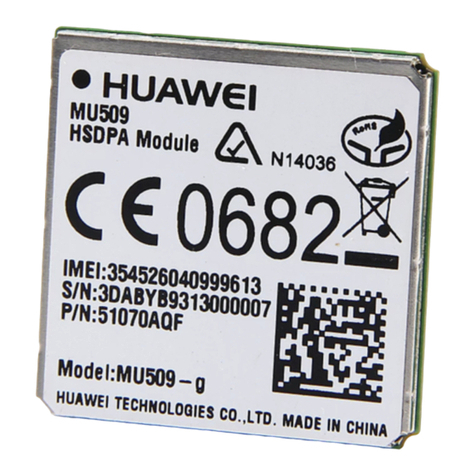
Huawei MU509 Series Hardware guide

Honeywell
Honeywell DirectLine DL423 user manual

Hanwha Vision
Hanwha Vision SPA-D2000 quick guide

Viessmann
Viessmann Vivotronic 050 HK1S Installation and service instructions
Quick
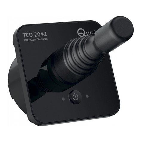
Quick TCD 2022 Installation and use manual

Xanavi Informatics Corporation
Xanavi Informatics Corporation HJZ0093 user manual
Siemens
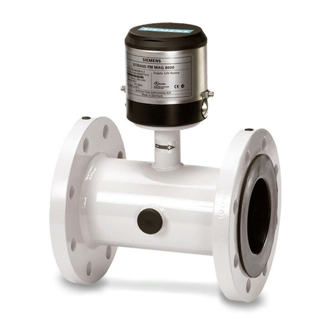
Siemens SITRANS F M MAG 8000 operating instructions
