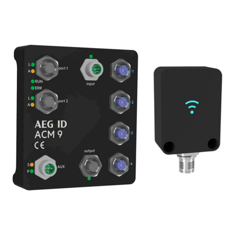
AEG ACM 9 User manual

Manual
ACM 9
ARE i9 – ARE i9x

Manual ACM 9 - ARE i9 release
Version:
10
Page:
2 / 51
Manual ACM9_ARE i9 release V10.docx
1. Introduction................................................................................................................................. 5
2. ACM 9.......................................................................................................................................... 6
2.1 Hardware ............................................................................................................................. 6
2.1.1 Dimensions ....................................................................................................................... 6
2.1.2 Protection Class................................................................................................................. 6
2.1.3 Connectivity...................................................................................................................... 7
2.1.4 Grounding ......................................................................................................................... 9
2.2 Firmware............................................................................................................................ 10
2.2.1 Industrial Ethernet description files .................................................................................. 10
2.2.2 Output data telegram from Industrial Ethernet master ...................................................... 10
2.2.3 Input data telegram to Industrial Ethernet master ............................................................. 10
2.2.4 ACM 9 – control via RS-232 serial interface ........................................................................ 11
2.2.5 ACM 9 error messages...................................................................................................... 12
2.2.6 Error messages coming through from ARE i9..................................................................... 13
3. ARE i9 - family............................................................................................................................ 14
3.1 ARE i9 Hardware................................................................................................................. 14
3.1.1 Dimensions ..................................................................................................................... 14
3.1.2 Protection Class............................................................................................................... 14
3.1.3 Connectivity.................................................................................................................... 15
3.1.4 Transponder orientation relative to ARE i9 ....................................................................... 16
3.1.5 Read range for SEMI application ....................................................................................... 17
3.1.6 Read range for miscellaneous applications ........................................................................ 19
3.2 ARE i9x Hardware ............................................................................................................... 20
3.2.1 Dimensions ..................................................................................................................... 20
3.2.2 Protection Class............................................................................................................... 21
3.2.3 Connectivity.................................................................................................................... 21
3.2.4 Transponder orientation relative to AAN Xi9F................................................................... 22
3.2.5 Read Range for SEMI Applications using AAN Xi9F ............................................................ 23
3.3 Firmware ARE i9 LF hdx - SEMI Industry............................................................................... 24
3.3.1 Instruction Set................................................................................................................. 24
3.3.2 General format of instruction set ...................................................................................... 24

Manual ACM 9 - ARE i9 release
Version:
10
Page:
3 / 51
Manual ACM9_ARE i9 release V10.docx
3.3.3 VER ................................................................................................................................ 24
3.3.4 GT .................................................................................................................................. 25
3.3.5 TOR ................................................................................................................................ 25
3.3.6 NID ................................................................................................................................. 26
3.3.7 CID.................................................................................................................................. 26
3.3.8 CN .................................................................................................................................. 27
3.3.9 RD .................................................................................................................................. 27
3.3.10 WD.............................................................................................................................. 27
3.3.11 LD............................................................................................................................... 28
3.3.12 VSAVE ........................................................................................................................ 28
3.3.13 INIT............................................................................................................................. 28
3.3.14 Error messages ............................................................................................................ 29
3.4 Firmware ARE i9 LF ............................................................................................................. 30
3.4.1 Instruction Set................................................................................................................. 30
3.4.2 General format of instruction set ...................................................................................... 30
3.4.3 VER ................................................................................................................................ 30
3.4.4 GT .................................................................................................................................. 31
3.4.5 TOR ................................................................................................................................ 31
3.4.6 NID ................................................................................................................................. 32
3.4.7 CID.................................................................................................................................. 32
3.4.8 CN .................................................................................................................................. 33
3.4.9 RD .................................................................................................................................. 33
3.4.10 WD.............................................................................................................................. 33
3.4.11 VSAVE ........................................................................................................................ 34
3.4.12 INIT............................................................................................................................. 34
3.4.13 Error messages ............................................................................................................ 35
3.4.14 ALGO .......................................................................................................................... 35
3.4.15 LOG (EM4305 chip specific)........................................................................................... 36
3.4.16 PWD (EM4305 chip specific).......................................................................................... 36
3.4.17 LD (EM4305 chip specific) ............................................................................................. 37
3.5 Firmware ARE i9 HF ............................................................................................................ 38
3.5.1 Instruction Set ................................................................................................................. 38

Manual ACM 9 - ARE i9 release
Version:
10
Page:
4 / 51
Manual ACM9_ARE i9 release V10.docx
3.5.2 General format of instruction set ...................................................................................... 38
3.5.3 VER ................................................................................................................................ 38
3.5.4 GT .................................................................................................................................. 39
3.5.5 TOR ................................................................................................................................ 39
3.5.6 CID.................................................................................................................................. 40
3.5.7 CN .................................................................................................................................. 40
3.5.8 RD .................................................................................................................................. 41
3.5.9 WD ................................................................................................................................. 41
3.5.10 VSAVE ........................................................................................................................ 41
3.5.11 INIT............................................................................................................................. 42
3.5.12 Error messages ............................................................................................................ 42
3.6 LED instruction set.............................................................................................................. 43
3.6.1 LED Standby (LSTB) ........................................................................................................ 44
3.6.2 LED Reading (LGT) .......................................................................................................... 44
3.6.3 LED Transponder number successfully read (LRD)............................................................. 45
3.6.4 LED No Read (LNRD)........................................................................................................ 45
3.6.5 LED Return to standby (LRT)............................................................................................ 45
3.6.6 LED Error (LERR) ............................................................................................................. 46
3.6.7 LED Process active........................................................................................................... 46
3.6.8 LED Process status........................................................................................................... 47
3.6.9 LED Setup help (FLED) ..................................................................................................... 47
3.6.10 LED (De)activate LED functionality (LED) ...................................................................... 48
4. System implementation ............................................................................................................. 49
4.1 Power supply...................................................................................................................... 49
4.2 Grounding .......................................................................................................................... 49
4.3 Mounting on metal............................................................................................................. 49
4.4 Frequency converters ......................................................................................................... 49
5. FCC Statement ........................................................................................................................... 50
5.1 ACM 9 ................................................................................................................................ 50
5.2 ARE i9................................................................................................................................. 50
6. Release, Change Protocol ........................................................................................................... 50

Manual ACM 9 - ARE i9 release
Version:
10
Page:
5 / 51
Manual ACM9_ARE i9 release V10.docx
1. Introduction
ACM 9 Industrial Ethernet (EtherCAT®, EtherNet/IP™, Profinet®), AEG ID Communication Module, provides Industrial
Ethernet connectivity for ARE i9, AEG ID RFID reader family. Both units are dedicated to each other, none of the two is
meant to be used without the other. Four ARE i9 units can be hooked up to one ACM 9.
EtherCAT® is a registered trademark and patented technology, licensed by Beckhoff Automation GmbH, Germany
EtherNet/IP™ is a trademark of ODVA (Open DeviceNet Vendor. Association, Inc)
PROFINET® is a registered trademark of PROFIBUS International, Karlsruhe.
Typical system structure
…
Industrial Ethernet
Master
24V DC
24V DC

Manual ACM 9 - ARE i9 release
Version:
10
Page:
6 / 51
Manual ACM9_ARE i9 release V10.docx
2. ACM 9
ACM 9 Industrial Ethernet communication module supports Industrial Ethernet connectivity. EtherCAT, EtherNet/IP and
Profinet are implemented (only one at a time). ACM 9 has 2 Industrial Ethernet ports, 4 serial ports dedicated to ARE i9
reader family, 4 digital inputs and 4 digital outputs, both linked to their respective reader port. The auxiliary port provides
power as well as a serial system interface. ACM 9 supports 32 byte cyclic input data and 32 byte cyclic output data.
2.1 Hardware
2.1.1 Dimensions
2.1.2 Protection Class
Protection class is IP65 assuming all cables and / or dummy caps are mounted.
IP67 available upon request.
111.6mm / 4.394 in
99,6mm / 3.921 in 24.5mm / 0.965 in
34.9mm / 1.374 in

Manual ACM 9 - ARE i9 release
Version:
10
Page:
7 / 51
Manual ACM9_ARE i9 release V10.docx
2.1.3 Connectivity
Auxiliary Port (AUX)
M12 socket 5 Pin male A-coded.
Industrial
Ethernet Port 1
Industrial
Ethernet Port 2
Auxiliary Port
Power + RS 232
4 digital Inputs
4 digital outputs
Serial Port 1 ARE i9
Serial Port 2 ARE i9
Serial Port 3 ARE i9
Serial Port 4 ARE i9
1
PIN 1 –nc
PIN 2 – RS-232 GND
PIN 3 – RS-232 TX (from ACM 9 point of view)
PIN 4 – RS-232 RX (from ACM 9 point of view)
PIN 5 – +24V DC / 3A
LED S: System interface LED
LED P: Power LED
Cable: M12, 5 Pin A-coded, socket to open end

Manual ACM 9 - ARE i9 release
Version:
10
Page:
8 / 51
Manual ACM9_ARE i9 release V10.docx
Industrial Ethernet Port (Port 1, Port 2)
M12 socket 4 Pin female D-coded (standard Industrial Ethernet)
Serial Ports for ARE i9 (1-4)
M12 socket 5 Pin female A-coded
PIN 1 – +7V
PIN 2 – GND
PIN 3 – TX
PIN 4 – RX
PIN 5 – nc
LED 1-4: Activity LED, cyan when in use
Cable: M12, 5-Pin A-coded, plug to socket
PIN 1 –TD+
PIN 2 – RD+
PIN 3 – TD-
PIN 4 – RD-
Profinet EtherNet/IP EtherCAT
LED L: Link LED L: Link LED LA: Link/Activity
LED A: Activity LED A: Activity -
LED SF: Collective failure LED MS: Mod Status LED RUN: system status
LED BF: Bus failure LED NS: Net Status LED ERR: failure LED
port 1 port 1 IN
port 2 port 2 OUT
Kabel: M12 4-Pin D-kodiert, Stecker und RJ45

Manual ACM 9 - ARE i9 release
Version:
10
Page:
9 / 51
Manual ACM9_ARE i9 release V10.docx
Digital Inputs (input)
M12 socket 8-Pin male A-coded
Digital outputs (output)
M12 socket 8-Pin female A-coded
2.1.4 Grounding
PIN 1 – Input for serial port 1
PIN 2 – Input for serial port 2
PIN 3 – Input for serial port 3
PIN 4 – Input for serial port 4
PIN 5 –7: not connected
PIN 8 -Input GND
LED : on, when any input is active
Input voltage 6..24VDC
Cable: M12, 8-pin A-coded socket to plug
PIN 1 – Output for serial port 1
PIN 2 – Output for serial port 2
PIN 3 – Output for serial port 3
PIN 4 – Output for serial port 4
PIN 5 – 7: not connected
PIN 8 – External output voltage
connected through PIN 1/2/3/4
LED : on, when any output is active
Switched voltage max: 125VAV / 60VDC
Switched current max: 1A | power max: 24W
Cable: M12, 8-pin A-coded plug to socket
Grounding ACM 9 is important for proper
functionality.
Grounding can be achieved in two ways:
1. Grounding via DIN hat rail clamp
The metal DIN hat rail clamp is connected
to internal ground of ACM 9. Grounding
DIN hat rail in machine will connect
internal ground to machine ground.
2. Use grounding pin on upper left side
(viewed from back).
Hook up machine ground to grounding
pin
PIN 1/2/3/4
PIN 8
6…24VDC
PIN 8
PIN 1/2/3/4
Max: 125VAC / 60VDC
Max: 1A
Max: 24W

Manual ACM 9 - ARE i9 release
Version:
10
Page:
10 / 51
Manual ACM9_ARE i9 release V10.docx
2.2 Firmware
ACM 9 uses 32 Byte cyclic input data and 32 Byte cyclic output data.
2.2.1 Industrial Ethernet description files
Profinet:
File GSDML-V2.35-AEGID-ACM9-20210310.xml contains Profinet description for ACM 9.
EtherCAT:
File ACM9_ECS_V2_1_0_10.xml contains EtherCAT description for ACM 9.
EtherNet/IP:
File ACM9_EIS_V3_1_0_7_2.eds contains EtherNet/IP description for ACM 9.
File names subject to change. Dowload latest files: www.aegid.de/en/documentation/acm9.php
2.2.2 Output data telegram from Industrial Ethernet master
The telegram starts with a change counter byte. This byte has to be changed, typically incremented, for every new
telegram. The second byte of the telegram is the serial interface port of the RFID reader. It can be ‘1’, ‘2’, ‘3’ or ‘4’ (0x31, 0x32,
0x33, 0x34). Starting from byte 3 the instruction text (instruction and parameters) for the reader is put in the following
bytes. The supported commands are documented in section ARE i9. The telegram must be closed with a carriage return
(0x0D). The complete telegram can be up to 32 byte long.
EXAMPLE:
The output data of the bus master to read a transponder code using ARE i9 on serial port 2 looks this way:
Hex:
01
32
47
54
0D
00
00
…
ASCII:
‘2’
‘G’
‘T’
<CR>
Meaning:
Change
counter
Serial
interface
port
Instruction Text End
character
2.2.3 Input data telegram to Industrial Ethernet master
Above output telegram has been sent to ACM 9. ACM 9 sends the command to the appropriate ARE i9, in this case to the
ARE i9 hooked up to serial interface port 2. ARE i9 reads the transponder code (UID of transponder) and sends it to ACM 9.
ACM 9 puts the transponder UID into the input data telegram frame for Industrial Ethernet master.
The telegram starts with a change counter byte. This byte is changed, typically incremented, for every new telegram ACM 9
puts on the bus. The second byte of the telegram is the serial interface port of the RFID reader. It can be ‘1’, ‘2’, ‘3’ or ‘4’
(0x31, 0x32, 0x33, 0x34). Starting from byte 3 the answer from ARE i9 (in this case the transponder UID) is put in the
following bytes. The telegram closes with a carriage return (0x0D). The complete telegram can be up to 32 byte long.
EXAMPLE:
The input data telegram for the Industrial Ethernet master is set by ACM 9 for example this way (UID = 1234567812345678):
Hex:
1F
32
31
32
…
38
0D
00
…
ASCII:
‘2’
‘1’
‘2’
…
‘8’
<CR>
Meaning Change
counter
Serial
interface
port
Transponder code End
character

Manual ACM 9 - ARE i9 release
Version:
10
Page:
11 / 51
Manual ACM9_ARE i9 release V10.docx
2.2.4 ACM 9 – control via RS-232 serial interface
In addition to the Industrial Ethernet control option, ACM 9 can always be controlled directly via a RS-232 interface. The
interface is located at the AUX port (see chapter 2.1.3 connectivity for pinout).
The serial parameters are: 115200 baud, 8 databits, 1 stopbit, no parity,
Communication is done via a simple ASCII based protocol. The same instruction set for ARE i9 is used as in Industrial
Ethernet communication (see section 3.2.x to 3.5.x for full list of instructions). Simply preceed the instruction with the port
number of the ARE i9 you want to talk to.
Examples:
Read firmware version of ARE i9 hooked up to port 2 of ACM 9:
Send ASCII string terminated with <CR> with preceeding port number via serial interface.
Input format: 2VER <CR>
Hex:
32
56
45
52
0D
ASCII:
‘2’
‘V’
‘E’
‘R’
<CR>
Output (example):2ARE i9 V_1.011 <CR>
Hex:
32
21
00
15
...
...
31
0D
ASCII:
‘2’
‘A’
‘R’
‘E’
...
...
‘1’
<CR>
The first number in the output string is the port number of ACM 9 that the instruction was sent to.
The rest of the string is the firmware version.
Read transponder UID from ARE i9 hooked up to port 4 of ACM 9:
Send ASCII string terminated with <CR> with preceeding port number via serial interface.
Input format: 4GT<CR>
Hex:
34
47
54
0D
ASCII:
‘4’
‘G’
‘T’
<CR>
Output (example):41234567812345678 <CR>
Hex:
34
31
32
33
...
...
38
0D
ASCII:
‘4’
‘1’
‘2’
‘3’
...
...
‘8’
<CR>
The first number in the output string is the port number of ACM 9 that the instruction was sent to.
The rest of the string is the transponder UID.

Manual ACM 9 - ARE i9 release
Version:
10
Page:
12 / 51
Manual ACM9_ARE i9 release V10.docx
2.2.5 ACM 9 error messages
ACM 9 itself has the following error messages.
Wrong channel number (Error code #65)
A wrong channel number is set to the master output data. Valid channel numbers are from ‘1’ to ‘4’.
Hex:
02
35
47
54
0D
00
00
…
ASCII:
‘5’
‘G’
‘T’
<CR>
Meaning:
Change
counter
Serial
interface
port
Instruction Text End
character
ACM 9 sets master input data to:
Hex:
20
00
15
23
36
35
0D
00
…
ASCII:
<NAK>
‘#’
‘6’
‘5’
<CR>
Meaning Change
counter
Serial
interface
port
Error Text End
character
Missing end character (Error code #66)
Missing end character (0x0D) in master output data. Each telegram has to be terminated by 0x0D (<CR>).
Hex:
03
34
47
54
00
00
00
…
ASCII:
‘4’
‘G’
‘T’
Meaning:
Change
counter
Serial
interface
port
Instruction Text
ACM 9 sets master input data to:
Hex:
21
00
15
23
36
36
0D
00
…
ASCII:
<NAK>
‘#’
‘6’
‘6’
<CR>
Meaning Change
counter
Serial
interface
port
Error Text End
character
Forbidden ARE i9 instruction (Error code #67)
Some ARE i9 instructions are not supported in an Ethernet bus environment. Those commands are not transferred to the
reader, but generate error #67.
Hex:
04
34
4D
44
20
30
0D
00
…
ASCII:
‘4’
‘M’
‘D’
<SP>
‘0’
<CR>
Meaning:
Change
counter
Serial
interface
port
Instruction Text End
character

Manual ACM 9 - ARE i9 release
Version:
10
Page:
13 / 51
Manual ACM9_ARE i9 release V10.docx
ACM 9 sets master input data to:
Hex:
23
00
15
23
36
37
0D
00
…
ASCII:
<NAK>
‘#’
‘6’
‘7’
<CR>
Meaning Change
counter
Serial
interface
port
Error Text End
character
2.2.6 Error messages coming through from ARE i9
Other error messages can be generated by the reader, if the reader command is wrong. See section ARE i9 for a detailed
description of those error messages. Below are sample error codes, see section ARE i9 for full list.
Wrong reader instruction (Error code #00)
A wrong reader instruction triggers error code #00.
Hex:
04
32
41
42
43
0D
00
…
ASCII:
‘2’
‘A’
‘B’
‘C’
<CR>
Meaning:
Change
counter
Serial
interface
port
Instruction Text End
character
ACM 9 sends this master input data:
Hex:
22
32
15
23
30
30
0D
00
…
ASCII:
‘2’
<NAK>
‘#’
‘0’
‘0’
<CR>
Meaning Change
counter
Serial
interface
port
Error Text End
character
Wrong reader instruction parameter (Error code #02)
A wrong reader instruction triggers error code #02.
Hex:
04
32
41
4C
47
4F
20
30
0D
ASCII:
‘2’
‘A’
‘L’
‘G’
‘O’
<SP>
‘0’
<CR>
Meaning:
Change
counter
Serial
interface
port
Instruction Text End
character
ACM 9 sends this master input data:
Hex:
22
32
15
23
30
32
0D
00
…
ASCII:
‘2’
<NAK>
‘#’
‘0’
‘2’
<CR>
Meaning Change
counter
Serial
interface
port
Error Text End
character

Manual ACM 9 - ARE i9 release
Version:
10
Page:
14 / 51
Manual ACM9_ARE i9 release V10.docx
3. ARE i9 - family
ARE i9 is a small industrial RFID reader that is available as a LF - SEMI Industry, LF and HF version.
ARE i9 LF hdx - SEMI Industry works with LF hdx transponders.
ARE i9 LF works with (all) low frequency transponders ASK, PSK, FSK, @ 125 KHz, 128kHz and 134.2 kHz (ISO 11784/11785).
ARE i9 HF works with all ISO 15693 compliant transponders.
3.1 ARE i9 Hardware
3.1.1 Dimensions
Recommended Screws for mounting: Cylinder head screw M4 x 30mm
3.1.2 Protection Class
Protection Class is IP 67, assuming cable or dummy cap is mounted.
40.8mm | 1.606 in 24mm | 0.945 in
30mm | 1.181 in
55.8mm | 2.197 in
71.9mm | 2.831 in

Manual ACM 9 - ARE i9 release
Version:
10
Page:
15 / 51
Manual ACM9_ARE i9 release V10.docx
3.1.3 Connectivity
ARE i9 is connected via its M12, 5-Pin male A-coded plug. Power supply as well as communication is provided by ACM 9,
communication module. Do not use any other means of powering or communicating to ARE i9 other than an ACM 9 module,
otherwise ARE i9 will be damaged. Do only use specified cables. ARE i9 uses a LED lit RFID symbol on its front side to
visually communicate its various states (standby, reading, successful read, no read, error, and so on...). When ARE i9 is
hooked up to ACM 9, the internal LED is switched to standby color. LED colors can be set by the user.
ARE i9 uses an air core coil. There is air core coil transponders like disks and ferrite core coil transponders like glass tube
transponders. It is important to understand the impact of orientation of transponders relative to ARE i9. Optimum
orientation is parallel to the front side of the reader for disks and perpendicular for glass tube transponders. In this
orientation, the highest read range can be achieved.
If it is not possible to ensure such orientation, the Disk transponders can be oriented perpendicular to the front side of ARE
i9 and glass tube transponders can be oriented parallel. This will result in some decrease of read range, but in most cases
this is acceptable.
PIN 1 – +7V
PIN 2 – GND
PIN 3 – RX
PIN 4 – TX
PIN 5 – CGND
LED: Status indication
Cable: M12, 5-Pin A-coded, plug to socket

Manual ACM 9 - ARE i9 release
Version:
10
Page:
16 / 51
Manual ACM9_ARE i9 release V10.docx
3.1.4 Transponder orientation relative to ARE i9
Disk parallel (recommended)
Glass transponder perpendicular (recommended)
Direction of travel
The highest read range is achieved right above the center of ARE i9 front side.
Disk Perpendicular
Glass parallel
Direction of
travel
In this orientation both transponder types are read best just outside the perimeter of ARE i9. There is a significantly
reduced read range in the center of ARE i9. This is no problem in a dynamic situation. Please ensure to start reading before
the transponder is above ARE i9 and keep reading until the transponder is beyond ARE i9.
Reading distance depends a lot on the particular installation. Absolute values only make sense based on a particular
transponder. Absolute values make no sense for transponder types, because the values will vary too much. Above is the
guiding principles to achieve the best possible read range.

Manual ACM 9 - ARE i9 release
Version:
10
Page:
17 / 51
Manual ACM9_ARE i9 release V10.docx
3.1.5 Read range for SEMI application
Glass transponder Texas Instruments RI-TRP-DR2B
Glass transponder perpendicular (recommended)
The highest read range is achieved right above the center of ARE i9 front side.
Glass parallel
The highest read range is achieved right at the perimeter of the reader housing.
*note: only one transponder in the field at a time. Above illustration only shows possible read ranges.
120mm
100mm
100mm
55mm
55mm
80mm
80mm
30mm

Manual ACM 9 - ARE i9 release
Version:
10
Page:
18 / 51
Manual ACM9_ARE i9 release V10.docx
For some applications where space contraints may prevent the use of ARE i9 in its recommended orientation that was
decribed above, it is also possible to read a SEMI glass tube transponder in the following way right above the small side of
ARE i9. Please note: Any other orientation of the glass tube does not work in this context.
65mm
50mm

Manual ACM 9 - ARE i9 release
Version:
10
Page:
19 / 51
Manual ACM9_ARE i9 release V10.docx
3.1.6 Read range for miscellaneous applications
Glass transponder and Disk transponder with different transponder chips (see table at the bottom)
Disk transponder parallel (recommended)
Glass transponder perpendicular (recommended)
The highest read range is achieved right above the center of ARE i9 front side.
Disk perpendicular
Glass parallel
The highest read range is achieved right at the perimeter of the reader housing.
*note: only one transponder in the field at a time. Above illustration only shows possible read ranges.
Type
Description
a
b
c
d
e
f
g
h
ID 1002/11/P/13
Disk, 13mm, PSK1
10
45
10
10
25
1
25
10
ID 1002/11/P/20
Disk, 20mm, PSK1
25
65
25
25
35
10
35
25
ID 1002/11/P/30
Disk, 30mm, PSK1
40
80
40
40
40
10
40
40
ID 1002/11/P/50
Disk, 50mm, PSK1
60
115
60
60
50
10
50
60
ID 102/11/P/3
Glass, 3mm, PSK1
1
35
1
1
25
1
25
1
ID 1002/0/A/13
Disk, 13mm, ASK
10
45
10
10
25
1
25
10
ID 1002/0/A/20
Disk, 20mm, ASK
25
65
25
25
35
10
35
25
ID 1002/0/A/30
Disk, 30mm, ASK
40
80
40
40
40
10
40
40
ID 1002/0/A/50
Disk, 50mm, ASK
60
115
60
60
50
10
50
60
ID 102/0/A/3
Glass, 3mm, ASK
1
35
1
1
25
1
25
1
Read range is given in mm.
Read range is typical read range. Actual read range may vary due to individual circumstances.
c
a
b
e
d
f
g
h

Manual ACM 9 - ARE i9 release
Version:
10
Page:
20 / 51
Manual ACM9_ARE i9 release V10.docx
3.2 ARE i9x Hardware
ARE i9x is a small industrial RFID reader that is available as a LF - SEMI Industry and LF version.
ARE i9x LF hdx - SEMI Industry works with LF hdx transponders.
ARE i9x LF works with (all) low frequency transponders ASK, PSK, FSK, @ 125 KHz, 128kHz and 134.2 kHz (ISO 11784/11785).
3.2.1 Dimensions
Recommended Screws for mounting: Cylinder head screw M4 x 30mm
AAN Xi9F
24mm | 0.945 in
30mm | 1.181 in
55.8mm | 2.197 in
85mm | 3.346 in
40.8mm | 1.606 in
46mm | 1.811 in
30mm | 1.181 in
10mm | 0.394 in
20mm | 0.787 in
24mm | 0.945 in
This manual suits for next models
2
Table of contents
Other AEG Control Unit manuals
Popular Control Unit manuals by other brands

Danfoss
Danfoss VHX-DUO Mounting guide

resideo
resideo Braukmann D05FS installation instructions

Festo
Festo FLSM operating instructions

Acuity Brands Lighting
Acuity Brands Lighting 5BPMW LED installation instructions

Grundig
Grundig GSS HRM 325 Assembly instruction

pizzato
pizzato CS AR-04 Series operating instructions