Selkirk Merlot User manual

PREFABRICATED WOOD-BURNING FIREPLACE
INSTALLATION AND OPERATION MANUAL
Keep this manual for future reference
Standards: ULC-S610
UL-127
EPA Phase II
Revised: June 2008 Web Site: www.maxfireplaces.com

2
TABLE OF CONTENTS
Page
INTRODUCTION..........................................................................................................................3
MERLOT FIREPLACE SPECIFICATIONS ................................................................................4
INSTALLATION...........................................................................................................................5
Fireplace Installation...................................................................................................................8
Door COMPONENTS..............................................................................................................11
Chimney Installation.................................................................................................................12
Installation Instructions for Masonry Application....................................................................12
Fireplace Finish.........................................................................................................................16
USE AND SAFETY.....................................................................................................................20
Creosote ....................................................................................................................................21
Chimney Fire Safety Procedures ..............................................................................................21
Feeding and Controlling Combustion.......................................................................................21
MAINTENANCE.........................................................................................................................23
Glass and Metal Plating............................................................................................................23
Replacing Refractory Bricks.....................................................................................................23
Door Installation and Alignment ..............................................................................................24
Gasket Replacement..................................................................................................................24
TROUBLESHOOTING...............................................................................................................25
HEAT DISTRIBUTION SYSTEMS...........................................................................................26
Gravity Distribution Kit............................................................................................................26
Forced Air Distribution Kit.......................................................................................................27
WARRANTY...............................................................................................................................29
Warranty Registration Card......................................................................................................30
Certification Plate....................................................................................................................31

3
INTRODUCTION
This manual contains all the information required for safe, efficient installation and use of your Selkirk
fireplace. Read carefully all the instructions contained herein and keep this manual handy so you may refer to it
whenever necessary.
Before starting to install the fireplace, consult local authorities to obtain a construction permit and learn
about all applicable regulatory requirements.
Do not install this fireplace in a mobile home.
Figure #1: Merlot Fireplace Dimensions
TOP VIE
W
LEFT SIDE VIE
W
FRONT VIE
W
RIGHT SIDE VIE
W
EXHAUST FLUE
6 po / 152 mm
GRAVITY AIR KIT
7 po / 178 mm
FORCED AIR
OUTLET FORCED AIR
OUTLET
ELECTRICAL
WIRE INLET
AIR INTAKE

4
MERLOT FIREPLACE SPECIFICATIONS
Maximum recommended heating area : 500 to 1,900 square feet (with forced air kit)
Heating capacity* – BTU/hr., EPA test wood : 36,900
Heating capacity* – BTU/hr., seasoned cordwood : 65,000
Optimum efficiency : 75%
*Why is the BTU indicated on the EPA label smaller than the one advertised?
You will notice a difference between the BTU output as indicated on the unit’s white EPA label affixed to the glass and the BTU as
advertised on our web site and/or product literature. The maximum BTU output we advertise for this unit is what will be obtained
with a full load of seasoned cordwood inserted inside the firebox. The EPA output, on the other hand, is what has been obtained
during emissions testing. The EPA test procedure requires that a special type of wood be used and positioned inside the firebox in a
manner that does not represent the way the firebox volume would normally be utilized using seasoned cordwood. The EPA test load is
typically much smaller. Hence, the BTU as per the EPA label is reduced. The BTU output that should be considered by a normal user
is the one we advertise for seasoned cordwood.

5
INSTALLATION
This fireplace is designed and approved for installation with the following brands of chimneys
measuring 6” (152 mm) in diameter as well as a minimum of 15’ (4.6 m) and maximum of 45’ (13.5 m) in
height.
No other device must be added to the chimney connected to the fireplace.
Selkirk, Sentinel(CF); SuperPro 2100(ALT);
SuperVent 2100 (JM) Selkirk, Ultra-Temp(UT); Sure-Temp(ST);
SuperPro(SPR), SuperVent(JSC); Hart&Cooley(TLC)
Install the fireplace only according to the methods described herein and ensure proper clearance is
provided to combustible. Use only the parts and chimneys specified in this manual. Any non-compliance with
these directions could create a hazardous situation, thus voiding the certification and the warranty.
ATTENTION: Do not modify or adapt the fireplace’s construction or components. This would void the
warranty. In this event, Selkirk would not be responsible for any damages which may
occur.
Choose the best location for your fireplace, based on the position of the doors and windows and room air
flow. Provide for the positioning of hot air ducts (optional), an outside air inlet as well as the chimney.
Remember to leave sufficient space for the hearth extension and mantel. If possible, install the fireplace where
it will not be necessary to cut any floor or ceiling joists. (Figure #2)
The fireplace must be installed against a finished wall. Do not install the fireplace against a moisture
barrier or insulation (insulating wool). Do not insert insulation into the enclosure around the chimney.
There are several possibilities for the chimney’s configuration. See Figure #3 to determine the
appropriate configuration for your home. The straighter the chimney, the easier it will be to clean and maintain.
For optimal performance, install the chimney indoors if possible. In areas where temperatures are constantly
below freezing (32°F/0°C), installing the chimney outdoors promotes functional problems such as low draft,
excessive creosoting, and problems starting the fire. In addition, outdoor chimneys are subject to decreases in
pressure and smoke flow reversal. Fireplaces with outdoor chimneys installed on lower floors (basements) are
particularly prone to smoke flow reversal. (Figure #3)

6
Figure #2: Various Fireplace Locations
Figure #3: Chimney Configurations
Outside air
inlet space

7
The table below shows the minimum chimney height requirements, fireplace included, according to the
number of elbows:
Chimne
y
Number of Elbows Minimum Hei
g
ht
Straight installatio
n
--------------- 15’ (4.6 m)
1 - 15° offset 2 - 15° elbows 15’ (4.6 m)
2 - 15° offsets 4 - 15° elbows 18’ (5.5 m)
1 - 30° offset 2 - 30° elbows 15’ (4.6 m)
2 - 30° offsets 4 - 30° elbows 20’ (6.1 m)
* 1 - 45° offset * 2 - 45° elbows 16’ (4.9 m)
* 2 - 45° offsets * 4 - 45° elbows 23’ (7.0 m)
* Permitted only in Canada.

8
FIREPLACE INSTALLATION
1. Remove all combustible floor coverings, e.g. carpeting, linoleum, etc., from the area where the fireplace is
to be installed.
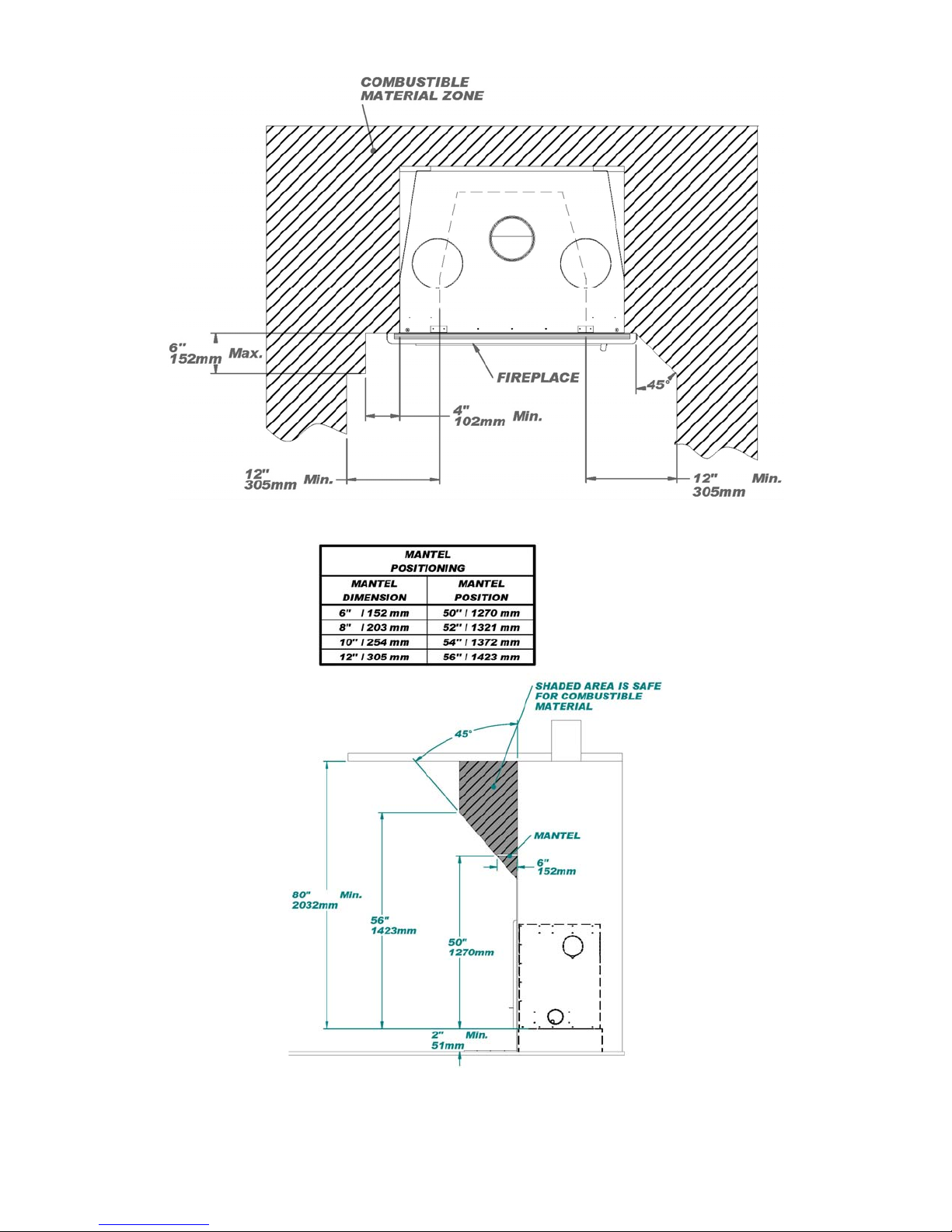
2. The fireplace must be installed directly on a platform with a minimum height of 2” (51 mm) and made of
combustible or non combustible materials, such as wood or plywood or any other hard, sturdy surface.
3. A 38” x 16” (965 mm x 407 mm) minimum hearth extension made of non combustible material is required.
The extension can be lower than or flush with the base of the fireplace. (Figures #5)
4. To prevent any burning embers falling between the fireplace and the hearth extension from coming into
contact with the floor, insert a metal sheet under the front of the fireplace. This sheet must extend 4”
(100 mm) on both sides of the fireplace and 2” (50 mm) in front. The non combustible hearth extension
should rest on the 2” band of sheet metal in front. You can also prevent embers from falling in the joint
between the fireplace and the hearth extension by filling it with mortar grout. (Figure #5)
5. To anchor the fireplace to the floor, unfold lower metal attachments and screw them to the floor using
1” (25 mm) screws.
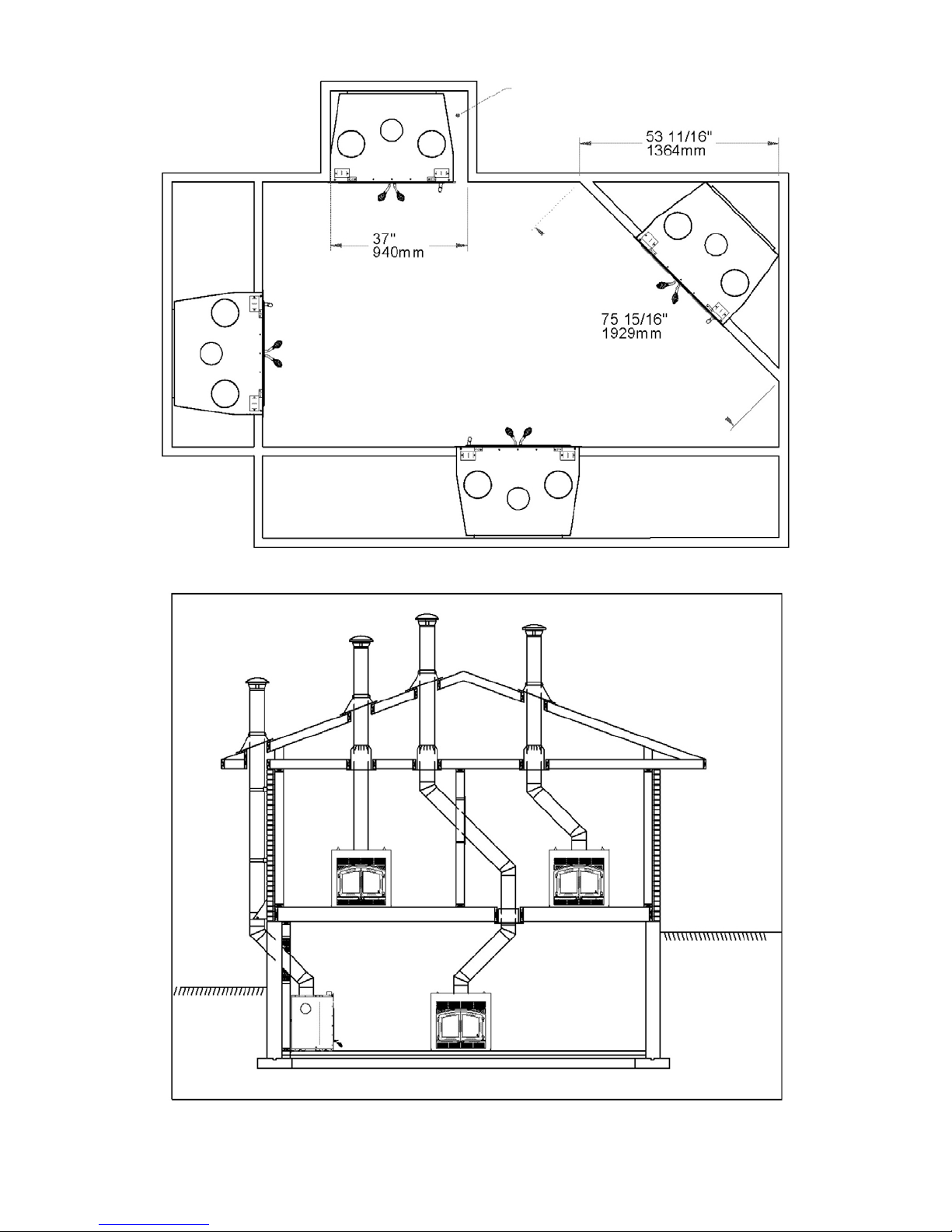
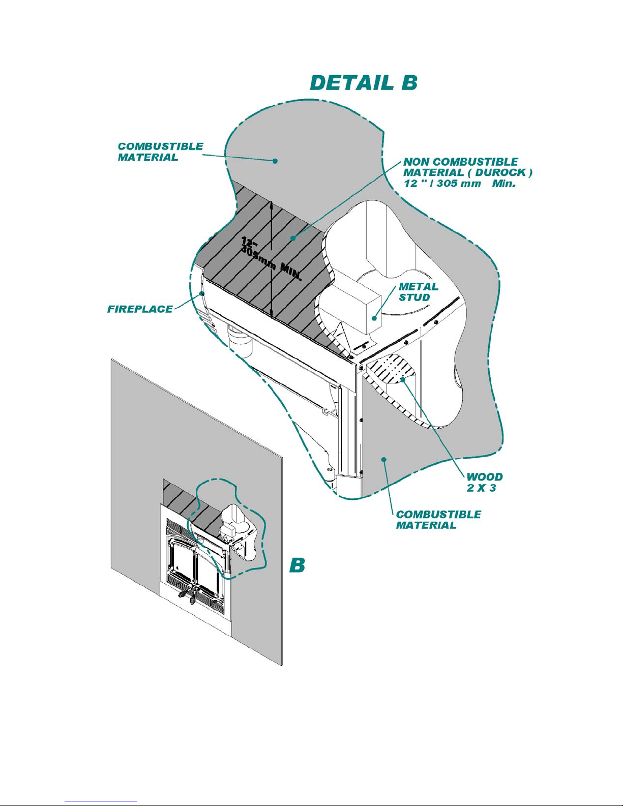
6. The opening must be at least 12” (305 mm) away from any wall at a right angle with the appliance’s face.
(Figure #11)
7. The standards in your area may require an outside air inlet. Even if this is not the case, it is beneficial to do
so as this will improve the fireplace’s performance. Install a flexible air duct that is 4” (102 mm) in
diameter and a maximum length of 20’ (6.1 m). If a longer duct is required, increase diameter to 6” but the
maximum length will then be 40’ (12.2 m). The outside air intake must not come from a garage, carport,
basement, attic or the chimney’s enclosure. If the outside air intake installation is impossible, the plate on
the outside air box must be removed. This plate is located at the bottom right inside the fireplace behind the
lower louver.
8. Install the outside air inlet in a place where it is unlikely to become blocked by snow and is sheltered from
high winds. Make sure it is far from the gas meter or any other device that may emit fumes or gases, such
as automobile exhaust.
9. Once you have decided on the location of the outside air inlet, drill a 4¼” (108 mm) hole in the wall. Insert
the inlet grill in the hole from the outside and screw it to the wall with four 1” (25 mm) screws.
10. From the inside, insert the insulated flexible duct and attach it to the inlet grill with aluminum duct tape or
¾” (19 mm) metal screws.
11. On the lower right side of the fireplace, remove the metal piece blocking the air intake. Insert the adaptor
included with the fireplace and screw it in place using two ¾” (19 mm) metal screws. Using an adjustable
collar or aluminum duct tape, attach the flexible duct to the adaptor.
12. Selkirk fireplaces can be equipped with a temperature control. The fan will come on as soon as the fireplace
reaches its minimum start temperature. Have the wiring installed by a qualified electrician (Figure #4).

9
Electrical Installation Instructions
12.1 Install the connection box on the bottom right of the fireplace behind the lower louver.
12.2 Install the fan on the pegs at the back of the fireplace behind the lower louver.
12.3 Connect the terminals onto the thermo-disc found under the fireplace floor.
12.4 Insert a 110-volt wire into the box through the appropriate hole.
12.5 Connect the wiring in the box.
12.6 Test the wiring.
12.7 Close the connection box.
Figure #4: Circuit Diagram

10
Figure #5: Hearth Extension Installation

11
DOOR COMPONENTS
Here is the drawing showing the components of your Merlot door.

12
CHIMNEY INSTALLATION
1. Assemble the first chimney section with the adaptor (provided by the chimney manufacturer) using three
¾” (19 mm) screws.
2. Screw this assembly to the fireplace using four ¾” (19 mm) screws.
3. Continue the installation following the instructions in the chimney manufacturer’s manual. (Figures #6
through #14)
4. To avoid overheating the walls of the enclosure, a minimum 2” (51 mm) clearance must be provided
between the chimney and any combustible materials. (Figures #12)
5. The chimney must rise at least 3’ (914 mm) over its juncture with the roof and exceed by at least
2’ (610 mm) any wall, roof or building located within a radius of 10’ (3 m). Any length of chimney
exceeding the roof by 5’ (1.5 m) or more, must be braced using tie rods or guy wires. (Figure #6.1)
6. To limit creosote formation, it is strongly recommended that an empty enclosure space be left between the
chimney stack and the outer framing of the chimney. Make sure that at all times a minimum clearance of
2” (51 mm) separates the chimney and any combustible materials.
NOTE: Since May 1997, whatever the type of fireplace or building, safety standards require that the fireplace
and the full length of an interior chimney up to the ceiling be enclosed.
WARNING: Before starting installation, the masonry chimney must be inspected by a qualified sweep.
INSTALLATION INSTRUCTIONS FOR MASONRY APPLICATION
The following requirements must be respected:
1. The chimney must be absolutely clear of any soot residue or creosote. Check for cracks, loose or missing
bricks that could inhibit correct installation of the liner.
2. The clearance to combustible must be a minimum of 1” between the outside of the masonry and any wood
framing or loose insulation.
3. The chimney must be built in accordance with the current building code.
4. No other appliance can be connected to the same chimney.
5. The connector parts are not necessary if the connection between the insulated length and the stainless steel
liner is done within the masonry chimney.

13
INSTALLATION
The chimney must be relined with a stainless steel liner or any other listed liner or flexible liner to
ULC-S635, ULC-S640 or UL777 of the same diameter as the outlet of the fireplace.
Follow these steps:
1. Position the fireplace in its location. Temporarily install the elbow on the top of the fireplace and, using a
level, mark with an oval the location where the flue liner will enter the masonry chimney.
2. In the middle of the oval, drill a hole in the masonry chimney at 45 or 30.
3. Increase the size of the hole until a 45 or 30 liner elbow can be easily slipped through.
4. Slide the liner down from the top of the masonry chimney until you reach the hole level.
5. Slip through the hole a 45 or 30 liner elbow and connect it to the liner.
6. Add a small liner section to the liner elbow which will allow the liner to extend at least 12” (measured at
the top of the liner) from the masonry chimney.
7. Seal the opening around the liner with high temperature refractory cement.
8. The next steps must be done in the following order:
8.1 Select the chimney length that will fit between the elbow and the liner so that it will slide at least 2”
over the liner section. (You may need to cut the liner for a better fit)
8.2 Install the 45 or 30 elbow on the fireplace.
8.3 Slide the length section back down on the elbow and twist lock the two together.
8.4 Pull the cover down over the length and install the insulation pad over the liner; be careful to cover the
liner completely.
8.5 Slide back the cover over the insulation and fix it in place using the 3 screws supplied.

14
Figure #6: Masonry Chimney Installation
Figure #6.1: Minimum Chimney Height
25"
640mm MIN. FROM
COMBUSTIBLE MATERIAL
STAINLESS STEEL LINER
FIRESTOP
W
ALL RADIATION
SHIELD *
INSULATION
PAD & COVER
FIREPLACE
A
NCHOR PLATE
INSULATED 45° ELBOW
LINER MUST SLIDE AT
LEAST 2" INSIDE LENGTH
HIGHT TEMP. CEMENT
LINER ELBO
W
MASONRY CHIMNEY
* NEEDED IF THE CHIMNEY PASS
THROUGH A COMBUSTIBLE WALL

15
Figure #7: Straight Chimney Installation Figure #8: Chimney with Elbows Installation
Figure #9: Exterior Chimney Installation Figure #10: Isolated Chase Chimney Installation

16
FIREPLACE FINISH
1. Combustible materials can be used to finish the fireplace in the area shown in Figure 11. The framing can
be built directly on the sides of the appliance.
2. No side wall of more than 6” (152 mm) wide at right angle with the face of the appliance can be closer than
4” (102 mm). (Figure #11)
3. Adjoining walls may also be built at a 45° angle from the edge of the face. However, any right angle wall
must be located at least 12” (305 mm) away from the fireplace opening. (Figure #11)
4. The enclosure from the bottom of the fireplace to the ceiling must be at least 80” (2032 mm). Do not insert
insulation in the chimney enclosure. (Figure #14)
5. Combustible materials must be installed parallel to the face and must not project behind. (Figure #13)
6. To avoid overheating the walls of the enclosure, a minimum 2” (51 mm) clearance must be provided
between the chimney and any combustible materials. Never fill the enclosure space with insulation or any
combustible material. If the fireplace is equipped with a gravity ventilation system, this space must be free
of any combustible materials. (Figure #14)
7. If the mantel is made of combustible materials, it must be installed at a height of at least 51” (1295 mm)
from the base of the fireplace. (Figure #12)
8. The top portion of the wall just above the fireplace must be made of 12” (305 mm) non combustible
material (Durock) (Figure #13). If finishing material are used within 12’’, they must be non-combustible.
9. The fireplace must be raised minimum 2” (51 mm) above the floor. (Figure #12)
WARNING: Make sure nothing obstructs or interferes with the front hot air outlets, to cover the front
hot air outlets it is mandatory to install gravity distribution kit. Any accessible chimney
must be fenced off or finished to prevent contact. (Figure #14)

17
Figure #11: Fireplace Finishing
Figure #12: Mantel Positioning

18
Figure #13: Installation of Combustible and Non-Combustible Materials

19
Figure #14: Chimney Enclosure

20
USE AND SAFETY
1. Teach children fireplace safety rules.
2. Do not use the fireplace under the following conditions:
2.1 Whenever a Refractory brick is missing or broken.
2.2 Whenever the ceramic glass is cracked or broken.
3. Never use flammable liquids to light or revive a fire and keep such products away from any heat source.
Before lighting a fire, make sure there are no flammable liquids, gases or fumes in the room.
4. When lighting the fire, adjust the air intake control (located at the bottom right of the fireplace) to its
maximum position. Do not leave the damper control in MAX position more than 30 minutes while the fire
is burning.
5. Prevent smoke flow reversal by preheating the chimney flue. Just hold a torch made of rolled up newspaper
towards the smoke chamber for a few minutes.
6. Selkirk fireplaces are designed to burn reasonable quantities of wood. Avoid making overly intense fires
that would damage the appliance. Do not burn garbage, painted wood or wood that has been exposed to salt
water.
DO NOT OVERHEAT
7. When using the fireplace for the first couple of times, make small fires to give the refractory brick time to
dry properly. The appearance of fine cracks in the refractory brick is normal and therefore not hazardous. It
is not cause for concern.
8. During the first fire, you may detect a certain odor and the coating and oil protecting certain appliance parts
may smoke a little. If you open a window, these will quickly dispel.
9. To light a fire, place balled-up newspaper in the combustion chamber. Crisscross kindling wood over the
newspaper, taking care to leave air space between the sticks. Adjust the air intake control to its maximum
position. Finally, light the newspaper. Once it is well lit, close the doors leaving a ½” (12.5 mm) opening
until the kindling is burning well. To sustain a nice fire, you should maintain a bed of burning embers.
10. Add larger pieces of wood, crisscross wood over the burning embers leaving air space between. Once the
fire is burning brightly, place 2 or 3 logs and close the doors slowly. Leave the air intake damper
completely open long enough to sustain combustion (maximum of 30 minutes).
11. If you close the doors too quickly, the temperature of the fireplace will reduce and consequently the fire’s
intensity will diminish.
12. Leave the air intake damper in maximum open position until the logs are burning brightly. Do not keep
feeding the fire with softwood kindling and construction waste wood, because these would produce a very
hot fire that may damage the combustion chamber.
13. Expansion and contraction noises during the heating and cooling cycle are normal. They are caused by the
normal expansion of fireplace components.
Table of contents
Other Selkirk Indoor Fireplace manuals
Popular Indoor Fireplace manuals by other brands

RealFlame
RealFlame HEATSEEKER 600 Installation & operating manual

Evonicfires
Evonicfires e1800 instructions

Heat & Glo
Heat & Glo GRAND-I35-C owner's manual

Heat & Glo
Heat & Glo SUPREME-N-I30AU owner's manual

foc.us
foc.us Slimfocus pivotant Specific instructions

Heat & Glo
Heat & Glo REVO-V12 owner's manual

Woodbridge Fireplace
Woodbridge Fireplace BDV2000NE Installation and operating instructions

Focal Point
Focal Point Centrurion 30 Installation, servecing and user instructions

Quality Craft
Quality Craft W913T-33BK instruction manual

Classic Flame
Classic Flame 23IIU42FGL manual

Austro Flamm
Austro Flamm KOKO XTRA 2.0 User instructions

Heat & Glo
Heat & Glo RED40-N-AU owner's manual