Selkirk FC Installation guide

1RM19957-2
10/09
CANADIAN
INSTALLATION
INSTRUCTIONS,
WARRANTY
AND
MAINTENANCE
GUIDE

2
®
RM19957-210/09
CAN/ULC-S604, CAN/ULC-S610
PLEASE READ ALL INSTRUCTIONS BEFORE BEGINNING YOUR INSTALLATION. FAILURE TO
INSTALL THIS SYSTEM IN ACCORDANCE WITH THESE INSTRUCTIONS WILL VOID THE
CONDITIONS OF CERTIFICATION AND THE MANUFACTURERS WARRANTY . KEEP
THESE INSTRUCTIONS IN A SAFE PLACE FOR FUTURE REFERENCE.
A MAJOR CAUSE OF CHIMNEY-RELATED
FIRES IS FAILURETO MAINTAIN REQUIRED
CLEARANCES (AIR SPACES)TO
COMBUSTIBLE MATERIALS.
IT IS OFTHE UTMOST IMPORTANCETHAT
THIS CHIMNEY BE INSTALLED ONLY IN
ACCORDANCE WITHTHESE INSTRUCTIONS.
MODEL FC FACTORY BUILT
INSULATED CHIMNEY
INSTALLATION INSTRUCTIONS
& MAINTENANCE GUIDE
LISTED

3
4
4
4
4 - 5
5
5 - 6
6
6
7
7 - 8
8 - 9
9
9
9 - 10
10 - 11
11
11
12
13
13
14
15
TYPES OF APPLIANCE
PRE INSTALLATION GUIDELINES
TOOLS
FRAMING DETAILS
CEILING SUPPORT INSTALLATION
STOVE PIPE INSTALLATION
ATTIC INSULATION SHIELD INSTALLATION
FIRESTOP RADIATION SHIELD INSTALLATION
ELBOW INSTALLATION
WALL SUPPORT INSTALLATION
CATHEDRAL CEILING SUPPORT INSTALLATION
ROOF SUPPORT INSTALLATION
RAFTER RADIATION SHIELD INSTALLATION
ROOF FLASHING INSTALLATION
ROOF GUY INSTALLATION
MAINTENANCE AND CLEANING OF CHIMNEY
REPLACEMENT PARTS LIST
CHART 1 - OFFSET TABLES
CHART 2 - CHIMNEY HEIGHT ABOVE ROOF
CHART 3 - CONNECTOR PIPE CLEARANCES
INSTALLATION RECORD & PRODUCT REGISTRATION
WARRANTY
TABLE OF CONTENTS

4
Plan your installation carefully. Lay out and frame in all openings
ensuring the specified 2” (50 mm) clearance to combustibles is
maintained. Seetable1. All openings should be square, plumb and
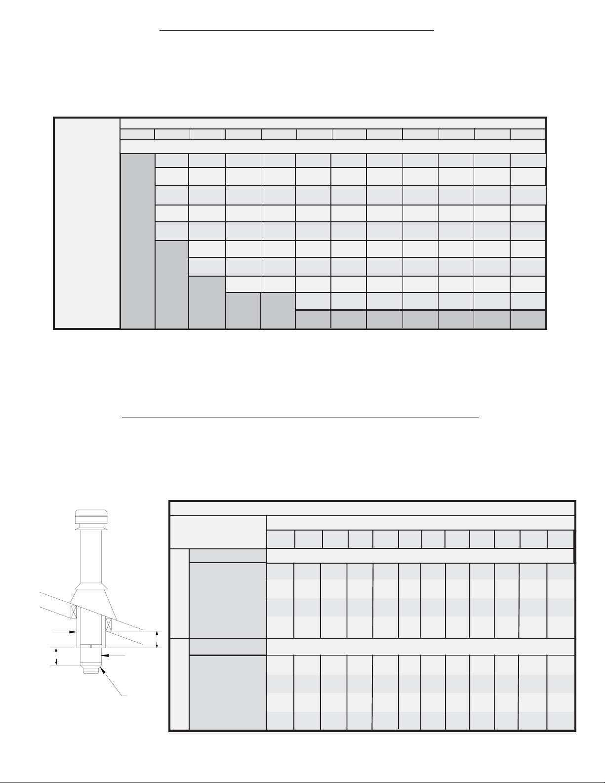
inperfectalignmentwitheachother. Seefigure2. Forslopingroofs,
ensure that the framing dimension is measured in the horizontal
plane. See figure 3.
TYPES OF APPLIANCES
Your SuperVent/SuperPro Model FC chimney is intended as a
component for specific listed factory built fireplaces and for
connectionto liquidfuelorgasfiredresidentialtypeappliancesand
buildingheatingappliances,inwhichthemaximumcontinuousflue
gas temperatures do not exceed 540 oC. It has been tested and
approved to withstand temperatures of up to 1125oC.
PRE-INSTALLATION GUIDELINES
Your SuperVent/SuperPro chimney and connecting stove pipe
diameter should be sized in accordance with the appliance
manufacturer’srecommendations.
Plan the installation of your appliance and chimney in such a way
thatyourbothyourchimney,andyourchimneyconnector(stovepipe)
run is as short and straight as possible. By having too long and or
multiple bend installations you can reduce system draft which can
affect the operation, and or performance of your appliance and or
chimney system. The chimney should also be located within the
buildingsoastoavoidcuttingoralteringloadbearingmemberssuch
as joists, rafters, studs, etc. If you require to cut or alter an existing
loadbearingmember,specialreframingmethodsarerequiredwhich
often include doubling of adjacent members. If such a case arises,
contactyourlocalBuildingCodeOfficialregardinglocalregulations
and proper installation methods.
Sections of the SuperVent/SuperPro chimney which pass through
accessibleareasofthebuilding,mustbeenclosedinachasetoavoid
personal contact and damage to the chimney. The chase may be
fabricated using standard building materials. Drywall mounted on
2” x 4” studs is typically used in this situation.
MAINTAIN A 2" (50mm) MINIMUM AIR SPACE CLEARANCE
BETWEEN INSULATED CHIMNEY SECTIONS AND
COMBUSTIBLE MATERIALS.
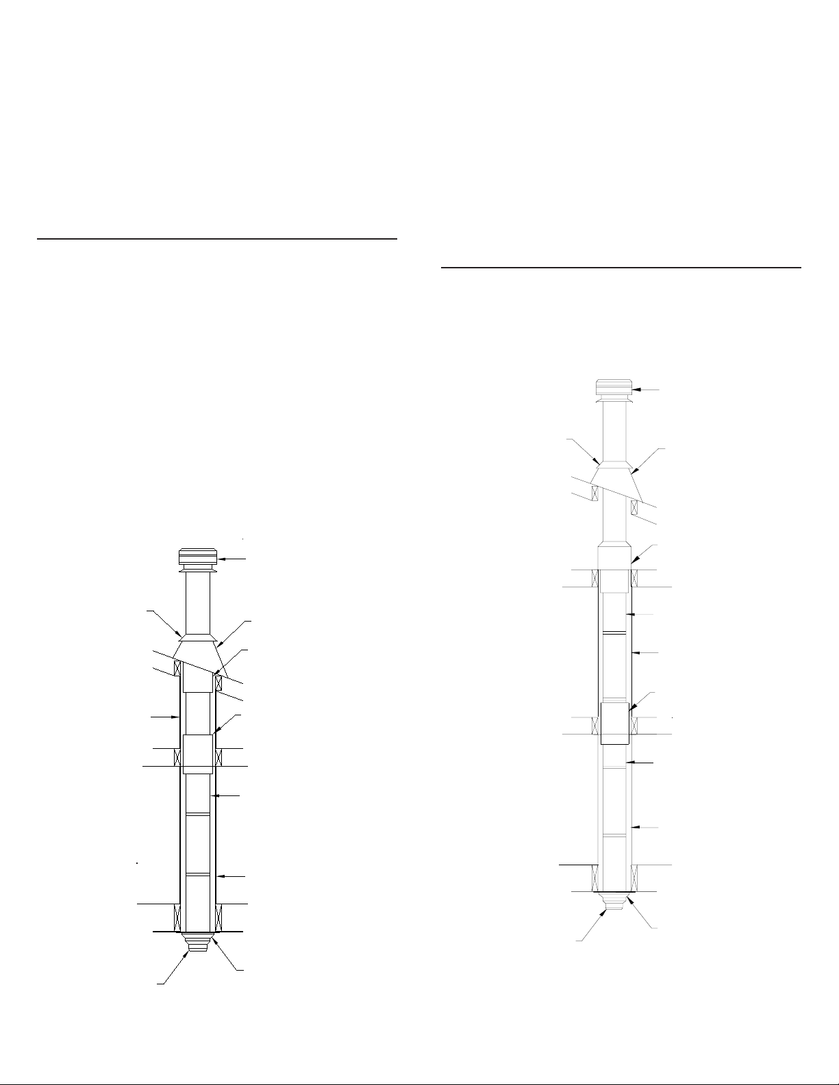
Authoritiesrequirethatthechimneyextendnotlessthan3feetabove
the highest point where it passes through the roof of a building and
notlessthan2feet(600mm)aboveanyportionofthebuildingwithin
10 feet (3m). See figure 1.
Theuseof Locking Bandsatall chimney jointsisrecommended for
added safety and stability when exposed to high winds and as a
precautionagainstaccidentalunlockingoflengthswhenthesystem
is inspected and swept.
The ideal location for your chimney system is within the building
envelope. Incold climates, theuse ofexternal chimneys mayresult
inoperationproblemssuchaspoor draft, excessivecondensationof
combustion products and rapid accumulation of creosote. Under
these circumstances, the installation of the chimney within the
building is strongly recommended.
If the chimney must be installed on an exterior wall it is highly
recommendedto enclose the chimney belowthe roof line to protect
itfromcoldoutdoortemperatures,thismayhelpreducecondensation,
creosote formation and enhance draft.
Do not install the chimney directly at the outlet of the appliance.
Interconnecting smoke pipe is required unless the appliance is
specifically approved for that type of installation.
Use only with an appliance listed by a recognized testing authority
such as Underwriters Laboratories Inc., Underwriters Laboratories
of Canada, Intertek Testing Services or Warnock Hersey.
The flue diameter of gas or oil fired appliances should comply with
theappropriateCSAorCGAInstallationCodes;/CAN/CSAB139.00,
CAN/CSA-B149.1-00 or CAN/CSA-B149.2-00.
YOUR CHIMNEY HAS BEEN TESTED, AND LISTED USING
ALL OF THE SUPPORTS, SHIELDS, ETC., DESCRIBED
HEREIN. DELETION OR MODIFICATION OF ANY OF THE
REQUIRED PARTS OR MATERIALS MAY SERIOUSLY
IMPAIR THE SAFETY OF YOUR INSTALLATION, AND
VOID THE CERITFICATION AND OR WARRANTY
OF THIS CHIMNEY
YourSuperVent/SuperProchimneysystemisdesignedforinstallation
using standard building materials and procedures. The following
tools will be required:
-safety gloves -screwdriver and pliers
-safety goggles -plumb line and level
-hammer and nails -square
-tin snips -spoke saw or power jig saw
Other tools or equipment may be required, depending on your
chimney location and the structure in which it is to be installed.
Except for installation in one and two family dwellings, a factory
builtchimneythatextendsthroughanyzone abovethatonwhichthe
connected appliance is located is to be provided with an enclosure
havingafireresistanceratingequaltoorgreaterthanthatofthefloor
or roof assemblies through which it passes.
Obtain any necessary building permits.
Ensurethatyouobtainanynecessarybuildingpermits,andthatyour
installation will conform with all federal and municipal building
code requirements. Before commencing installation,
CONTACT LOCAL BUILDING OR FIRE OFFICIALS ABOUT
RESTRICTIONS AND INSTALLATION
INSPECTION IN YOUR AREA.
WARNING: DO NOT PLACE ANY INSULATING
MATERIALS OR RUN ANY ELECTRICAL WIRING
WITHIN THE REQUIRED AIR CLEARANCE SPACE
SURROUNDING THE CHIMNEY.
3 ft. (900mm)
min.
3 ft. (900mm)
min.
10 ft.
(3m)
2 ft.
(600mm)
2 ft.
(600mm)
FIGURE 1
TOOLS
FRAMING DETAILS

5
6"
(125mm)
7"
(175mm)
8"
(200mm)
mm
mm
mm
5"
(150mm) mm 11 x 11
280 x 280
13 x 13
330 x 330
14 x 14
123/8x 123/8
315 x 315 143/8x 143/8
365 x 365
133/8x 133/8143/8x 143/8
340 x 340 365 x 365
143/8x 143/8
365 x 365 355 x 355365 x 365
143/8x 143/8
12 x 12
305 x 305
123/8x 123/8
315 x 315 143/8x 143/8
365 x 365
-15o,30oor45oChimneyElbows(ModelFC)-andsuitablesupports
JSC RS, or JSC ES, if required.
- Rain Cap: JSC RC or DRC - Standard or Deluxe model.
Center this first chimney section in the Ceiling Support and from
beneath the support insert the stove pipe adaptor and lock it into
placebyturningclockwiseuntiltight. Thiswill holdyourchimney
in place while the rest of your installation is completed.
Install additional chimney sections and lock together by turning
clockwise until the two sections lock together tightly. Install a
lockingband tosecure thetwo chimney sections. Continue adding
chimney lengths until a height of about 2 feet (600mm) below the
next ceiling level is achieved.
Single Story Installation
CEILING SUPPORT
To complete a proper decorator ceiling support installation, the
following parts may be required:
- Decorator Ceiling Support: JSC DCS
- Attic Insulation Shield: JSC AIS-C - Required where a chimney
passes into an unoccupied attic space.
- Firestop Radiation Shield: JSC FRS - Required where a chimney
passes from a lower living space into an upper living space or
occupied attic space.
-RoofFlashingAssembly: JSCAAF,orJFCAF2-Requiredwhen
the chimney penetrates a roof.
INSTALLATION PROCEDURES:
TABLE 1 Decorator
Ceiling
Support
Wall (Sup-
port)
Thimble
Framing Dimensions
All Other
Framing
Chimney Flue
Diameter
FIGURE 3
Typical Roof
Joist Framing
FIGURE 2
Typical Joist
Framing
in.
in.
in.
in.
Attic Space
Ventilated Flashing
Stove Pipe Adaptor
Storm Collar
Chimney Sections
Attic Insulation Shield
Ceiling Joist
(Framed all 4 sides)
FIGURE 4
Roof Joist
(Framed all 4 sides)
2"
(50mm)
Min
2"
(50mm)
Min
2"(50mm)
Min
2"
(50mm)
Min
Raincap
Ceiling Support
- Rafter Radiation Shield: JSC RRS - Required when the chimney
is enclosed immediately below the roof.
- Suitable lengths of Chimney (Model FC). The chimney diameter
should be sized to suit the appliance.
STOVE PIPE INSTALLATION
TheStovePipeAdaptor(ASE)isinstalledbytwist-lockingitintothe
bottom end (female end) of the first Chimney Section that enters the
CeilingSupport. DonotinstallanelbowintheCeilingSupport. Make
surethatthemalecoupleroftheinsulatedChimneyLengthispointing
upwards as indicated by the arrow on the chimney label. Lower the
assembly down into the Support ensuring that the stovepipe adaptor
sleeveisprotrudingthroughthesupportandintothelivingspace(see
Figure 5).
The crimped end (stub) of the Stove Pipe Adaptor is intended to fit
inside of the flue pipe from a solid fuel appliance, thus preventing
condensatedripsatthechimneyconnection. Insomeapplication,the
crimped end will need to be removed as per fuel requirements and
local installation codes.
The Decorator Ceiling Support will support up to 50 feet (15.25m)
of chimney sections, all of which must be installed above the
support. Figures4&5showthe2mostcommontypesofDecorator
Ceiling Support Installation.
Slide the Trim Ring onto the Ceiling Support and slide assembly
into framed opening from below. Ensure that the finishing plate is
flushwiththeundersideoftheceilingandtheassemblyisleveland
plumb. Hammer 12 6d or (2”) nails through each of the 4 straps.
Lower the first section of chimney (with the Stove Pipe Adaptor
installed on the female end) into the Ceiling Support ensuring that
the male coupler is pointing upwards, as indicated by the arrow on
thechimneylabel. NOTE:SeenextsectionforStovePipeAdaptor.
Chimney Length
Stove Pipe Adaptor
(ASE)
Decorator
Ceiling Support
FIGURE 5
Install inter-connecting flue pipe following the appliance
manufacturer's installation instructions and appropriate building
code requirements keeping in mind that the flue pipe run should be
asshortandstraightasproacticable. Generally,forawoodburning

6
ATTIC INSULATION SHIELD FIRESTOP RADIATION SHIELD
A Firestop Radiation Shield must be installed where the chimney
passes from one living space to another living space, as shown in
figure7. Itisdesignedtoprovideproperfirestoppingbetweenfloors
and to keep direct radiation from the chimney away from the joist
framing.
An Attic Insulation Shield must be installed where the chimney enters
anatticspace. Itisdesignedtokeepinsulationmaterialsawayfromthe
chimney and will protect up to a 10 inch (250 mm) thickness of
insulation plus the depth of the ceiling joist.
Where height restrictions will not permit the use of the Attic
Insulation Shield, an enclosure from the attic joist to the roof joist
will be sufficient. All chimney enclosures must maintain the
required minimum air space clearance of 2" to the chimney. When
enclosingthechimneybelowtheroofline,aRafterRadiationShield
(RRS) must be installed at the roof level and a Firestop Radiation
Shield (FRS) at the ceiling level (see Figure 6). For proper installa-
tion, the attic opening must be fully framed at 2 inches of clearance
to the chimney pipe with framing material of the same stock as the
ceilingjoistandaspertheFramingDimensionTable1. Thetabson
the plate are inserted in the framed opening around the chimney.
NailtheAISbasetotheframingwithatleast2perside,using2d(1")
spiral nails or 1" x #8 wood screws.
Decorator Ceiling Support
Stove Pipe Adaptor
Floor, Ceiling Joist
(Framed all 4 sides)
Ceiling Joist
(Framed all 4 sides)
Chimney Sections
Two Story
Main Floor Installation
Roof Joist
(Framed all 4 sides)
Two Story
Basement Installation
Storm Collar VentilatedFlashing
Chimney Sections
Ceiling Support
Stove Pipe Adaptor
Ceiling Joist
(Framed all 4 sides)
Roof Joist
(Framed all 4 sides)
Firestop Radiation Shield
Storm Collar Ventilated Flashing
Rafter Radiation Shield
Floor, Ceiling Joist
(Framed all 4 sides)
Floor, Ceiling Joist
(Framed all 4 sides)
Chimney Sections
Firestop Radiation Shield
Attic Insulation Shield
Living Space
Attic Space
FIGURE 6
FIGURE 7
Enclosure
Enclosure
Living Space
Living Space
Attic Space
Enclosure
Enclosure
Raincap
Raincap
Generally,forawoodburningapplianceinstallation,an18"minimum
clearance to combustibles must be maintained for a single wall flue
pipe. The exception to this is a double wall stove pipe, such as
Selkirk'sModelDSPwhichcanbeinstalledatreducedclearancesof
6" to combustibles. See separate installation instructions for more
details.
Installadditionalchimneysectionsandlocktogethertightly. Install
a Locking Band to secure the two chimney sections together.
Continue adding chimney lengths until a height of about 2ft below
the next ceiling level is achieved.
When an Attic Insulation Shield is required above the Decorator
CeilingSupportintoanatticasshowninFigure4,ensurethatthebase
oftheshieldisflushwiththetopofthejoistframingandnaileinplace.
Thetelescoping portion ofthe AISwill eliminate theneed totrim the
bottom when installed immediately above this support. When fully
extended,theAISwillalsoprovidejoistshieldingwheninstalledina
2 story main floor or basement application (see Figure 7).
NOTE:Tostopcoldairinfiltrationintothedwellingyoucaninstallthe
optionalUniversalShieldingInsulation(JUSI)intotheAtticInsulation
Shield. See separate installation instructions packaged with the JUSI.

7
Stove Pipe Adaptor
Elbow Support Bands
Ceiling Joist
(Framed all 4 sides)
Floor, Ceiling Joist
(Framed all 4 sides)
Wall Support Installation
WALL SUPPORT
TocompleteaproperWallSupportinstallation,thefollowingparts
may be required:
- Adjustable Wall Support: JSC AWS.
- Roof Flashing Assembly: JSC AAF, JSC AF2
- Required when the chimney penetrates a roof or a roof overhang.
- Rafter Radiation Shield: JSC RRS - Required when the chimney
is enclosed immediately below the roof.
- Wall Bands: JSC WB.
-Suitablelengths ofchimney(Model FC). The chimney diameter
should be sized to suit the appliance.
- Rain Cap: JSC RC or DRC - Standard or Deluxe model.
NOTE: NEVER OFFSET AN EXTERIOR CHIMNEY.
FIGURE 9
TheSuperVent/SuperPro AdjustableWall Supportwill supportup
to 38 feet (11.5m) of chimney, all of which must be above the
supportwiththeexception ofthe1footcleanoutsectionand/orthe
Insulated Tee Plug, which is installed below the support.
Onepairof(two)15oor30oelbowsmaybeusedtoprovideanoffset
in order to avoid cutting of joists and to clear other obstructions.
Eachelbowsupportwillsupport15feet(4.5m)ofchimneyandthe
Maximum length of chimney allowed between the elbows is 6 feet
(2 m).
The female end of the elbows are not lanced, in order to ensure
properalignment ofthe chimneysystem can be maintained. Lock-
ing bands must be used at all chimney joints.
Never install an elbow in a joist area. Chimney sections must pass
vertically through framed joist areas.
During installation provide supplementary support for the offset
section to avoid undue stress on connected elbows.
Install an elbow support just above the highest elbow. Attach the
Support Band to the chimney with 4 of the nuts and bolts, and then
install the four stainless steel sheet metal screws through the pre-
punched holes. Attach the Support Straps to the Support Band
assemblyandnailtheSupportStrapstotheframingusing6d(or2”)
nails. See figure 8.
ELBOW INSTALLATION
Roof Joist
(Framed all 4 sides)
Elbow Support Straps
Decorator Ceiling Support
Living Space
Attic Space
Offset (Elbow) Installation
Raincap
Storm Collar
Wall Band
Locking Band
InsulatedTee
Wall Support
1 Foot
Chimney Section or
an Insulated Tee Plug
Chimney Section
Stove Pipe Adaptor
Wall Thimble
Inner Half
Wall Thimble
Outer Half
Ventilated Flashing
Attic Insulation Shield
Ventilated Flashing
FIGURE 8
Locking Bands
Elbow
Storm Collar
Enclosure
Locking Bands
8 Feet
(Max)
Tee Plug
3"Minimum
Elbow
Raincap
Chimney Sections
InstalltheFirestopJoistShield from eitheraboveorbelowthejoist
framingandnailinplace using1"spiralnails. Ensurenoinsulation
is within the 2" air space clearance around the chimney. This
includes the air spaces between the Firestop Radiation Shield and
the joist framing.

8
Installawallbandmidwayupthefirstchimneylengthabovethetee.
Wallbandsmustthenbeinstalledata8foot(2.4m)intervalsabove
this point. See figure 9. The nut and bolt supplied will fasten the
bandaround the chimney. Secure the wall band bracketto thewall
using two 6d or 2” spiral nails. For concrete walls use suitable
masonryfasteners.
If the total chimney height exceeds the wall support limitations, an
AdjustableIntermediateWallSupportJSCAIWSmustbeinstalled.
Use of an AIWS will support another 38 ft. (11.5m) of chimney.
Slide the assembled intermediate wall support over the protruding
lengthofchimney. Fastentheintermediatewallsupporttothe wall
usingfour1/4”by2”woodscrewsthroughthepre-punchedslotsin
eachbracket. Installthe drawbandaround the protrudingchimney
lengthsecurelyagainstthesupportplate. Installfourstainlesssteel
sheet metal screws firmly into the outer casing of the chimney,
through the pre-punched holes in the draw band.
After framing in your opening to the dimensions specified in the
FramingDetailssection,installtheouterhalf(withsquareplate) of
the wall thimble in the outside wall surface. Secure in place using
appropriate fasteners using all of the pre-punched holes. For
concrete walls, cut a hole slightly larger than the chimney.
Install the inner half (with round plate) of the wall thimble in the
insidewallsurface, Ensuringthattheshieldslidesintotheshieldof
the outer half. Once in place and flush against the wall, install the
trimplateandfasteninplacewithappropriatefastenersthroughthe
four pre-punched holes.
NOTE:Tostopcoldairinfiltrationintothedwellingyoucaninstall
the optional Universal Shielding Insulation (JUSI) into the Wall
Thimble. See separate installation instructions packaged with the
JUSI.
Assemble the Wall Support (Figure 10) by attaching the 2 side
brackets to the support plate, with the hardware supplied (female
coupler attached to the plate is down).
To complete a proper Cathedral Ceiling Support installation, the
following parts may be required:
- Cathedral Ceiling Support: JSC CCS.
- Roof Flashing Assembly: JSC AAF, JSC AF2
- required when the chimney penetrates a roof.
- Suitablelengthsof chimney(Model FC). The chimneydiameter
should be sized to suit the appliance.
- Rain Cap: JSC RC or DRC - Standard or Deluxe model.
TheCathedralCeilingSupportwillsupportatotalof38feet(11.5m),
ofchimney. Chimneyjointsmadebelowthesupportmustbesecured
with locking bands.
After framing in your opening to the dimensions specified in the
Framing Details section, slide the Cathedral Support box into joist
opening. Oncetheboxisatthedesiredlevel,ensureboxisleveland
nail the box to framing using four 2” spiral nails or equivalent per
side. The excess material sticking above the roof can either be
trimmed off before attaching the box to the framing or, after it is
installedthecornerscanbecutandtheexcessmaterialfoldeddown
onto the roof deck.
Install the Support Band on the Chimney length at the desired
position by tightening the draw band bolt and by screwing four
stainlesssteelsheetmetalscrewsthroughthedrawbandandintothe
outercasing. Lowerthechimneylength down through theopening
inthebottomofthesupportsothattheSupportBandmakescontact
with the bottom of the Support Box. (See Figure 11).
4 painted ceiling trim angles (2 short & 2 long) are supplied with
fastening screws to finish off the Support Box at the ceiling level.
The 2 long pieces are trimmed off to match the pitch of the ceiling.
NOTE: The male coupler of each chimney length must be up.
NOTE:Tostopcoldairinfiltrationintothedwellingyoucaninstall
theoptionalUniversalShieldingInsulation(JUSI)intotheCathedral
Support. See separate installation instructions packaged with the
JUSI.
CATHEDRAL CEILING SUPPORT
Bolt
Support Plate
Female Coupler
(Down)
FIGURE 10
Installaonefoot(orlongerasrequired)lengthofinsulatedchimney
tothehorizontal branch oftheinsulatedtee. Lock securely intothe
teebytwisting clockwise. A lockingbandmust then beinstalledat
this connection. Make sure the nut and bolt are facing down to
prevent any water from collecting in the locking band.
NOTE: THE CHIMNEY MUST EXTEND AT LEAST
3” (75 MM) INTO THE LIVING SPACE WHERE THE
STOVE PIPE CONNECTOR WILL BE ATTACHED TO
THE CHIMNEY BRANCH.
From outside the building, slide the chimney length (previously
installed on a tee) through the wall thimble ensuring the male
coupling on a tee is facing upward.
Place the adapter ring (Figure 10) on the wall support so that the
sleeve on the adapter drops through the hole in the support plate.
Placetheassembledwallsupportagainstthewall(plateup)directly
below the tee. Slide wall support up to the tee ensuring that the
adapter on the wall support engages with the female coupler of the
tee. Ensurethewallsupportislevel,andsecuretothewallwithfour
1/4”by2”LagBoltsthroughthe pre-punchedslotsineachbracket.
Ifthesupportisproperlypositioned,theselagboltswillgointowall
studs placed on 16”(405mm) centers.
Adapter Ring
Nut
Side Bracket
Side Bracket

9
Slide the Roof Support down over the chimney section until its
brackets rest on the roof or floor. Tighten the collar around the
chimney with the nuts and bolts supplied, then secure the collar by
screwingthe6suppliedmetalscrewsthroughtheholesinthecollar
and into the chimney.
Center the chimney in the joist and nail or screw the support to the
roof or floor using the 12 - 3 1/2” spiral nails supplied or 12 #8 x
1 1/4 wood screws.
Install additional chimney sections and lock together by turning
clockwise until the two sections lock together tightly - continue in
this manner until the desired height is achieved.
NOTE: The male coupler of each chimney length must be up.
RAFTER RADIATION SHIELD:
A Rafter Radiation Shield must be installed where the chimney is
enclosedimmediatelybelowtherooflineasshowninfigure15. An
example of this is when the attic space of a house is being used as
living space (ie. bedroom, guestroom etc.)
Attach the support brackets to the shield (through one of the three
pre-punched holes) such that once the shield is installed, the shield
protectsboththeupperandlowerpartsoftheroofjoistframing(See
figures 13 & 16).
Rafter Radiation Shield AssemblyFIGURE 13
Shield
Bracket
Screw
ROOF FLASHING:
Ensurethatyouhavetheproperroofflashingbycheckingyourroof
pitch using a level and two rulers (see fig. 14) or by using a roof
pitch card.
The JSC AAF flashing is for roof pitches from Flat to 6/12.
The JSC AF2 flashing is for roof pitches from 6/12 to 12/12.
Thebottomchimneylength(s)shouldprotrudeintothelivingspace
so that proper clearances are maintained on the stove pipe connec-
tor.
Install additional chimney sections and lock together by turning
clockwise until the two sections lock together tightly. Continue in
this manner until the required height above the roof is achieved.
Chimney sections (15 feet or 4.5m max.) installed below the
Cathedral Ceiling Support are locked together from below by
turningclockwiseuntiltightlylockedtogetherwitheachjointbeing
secured by a locking band.
Cathedral Ceiling Support InstallationFIGURE 11
Storm Collar
Chimney Sections
Raincap
VentilatedFlashing
Stove Pipe Adaptor
Support Box
Support Ring
ROOF SUPPORT
TheRoof Supportmaybeusedonafloor,ceilingorroofandadjusts
toanyroofpitch. Itmaybeusedaboveanoffsettosupporttheoffset
orasasupplementarysupportwhenthechimneyheightexceedsthat
oftheprimarysupport. TheRoofSupportwillsupportatotalheight
of 50 feet (15m) of chimney sections. All chimney sections below
the support must be secured with locking bands.
Attach the support brackets to the support band with the 1/2” nuts,
boltsandlockwashers. Thelockwasherisplacedbetweentheband
and support bracket to provide proper spacing as shown in
Figure 12.
FIGURE 12 Roof Support Assembly
Nut
Lock Washer
Support Band
Carriage Bolt Support
Bracket

10 Roof Guy Installation
Ensurethat the chimney is plumb. Square up theflashing plateand
nail in place to the roof deck. Use 12 nails with neoprene washers
orcovertheheadswithasuitablewaterproofmastic. Atthetopedge
of the flashing plate, lift the shingles and nail the plate to the roof
deck. Then cement shingles to the plate with a suitable waterproof
mastic.
Wrap the Storm Collar around the chimney above the flashing.
Secure the ends together loosely with the nut and bolt supplied.
Slide the collar down the chimney until it contacts the flashing.
Tighten the nut and bolt and seal the Storm Collar to the chimney
with a suitable waterproof non-combustible mastic. After installa-
tionchecktoensurethattheventilationslotsarenotobstructed(See
Figure 16).
NOTE:ARubberBootFlashingKit(URBFK1)isavailableasan
optionfor passingthrough a corrugatedor metalroof. See separate
instructionspackagedwith theRubberBoot Flashng Kit. Onmetal
or steep roof, it is recommended that a chimney cricket fabricated
fromheavy-guagegalvanizedsteelbeinstalled. Thiswillprotectthe
Chimney and the Flashing by routing the snow load and ice around
the chimney. This is not a supplied item. Contact a sheet metal
fabrication shop in your area for your custome chimney cricket.
Shingles
Flashing
Nails
Level
Roof
Pitch is 3/12
3"
12" Ruler
FIGURE 14 Roof Pitch Calculation
SlideaRoofFlashingAssemblysuitabletoyourroofslopeoverthe
chimney. Place the top edge of flashing plate under the shingles.
Placebothsidesandtheloweredgeontopoftheshingles(Seefigure
15). Do not nail in place at this time.
Roof Flashing Installation
FIGURE 15
Enclosure
RafterRadiation
Shield
Flashing
Storm Collar
Ventilation Slots
Raincap
WARNING: DO NOT BLOCK THE VENTILATION
SLOTS ON THE FLASHING.
The flashing and storm collar should be painted to match the roof
shingles. This will extend its life and improve the appearance.
Clean, prime and paint with suitable painting products.
Continueaddingchimneylengthsuntiltheproperheightisachieved
(See figure 1). Install the rain cap and lock it in place by turning
clockwise until tight.
FIGURE 16 Storm Collar/Flashing Installation
FIGURE 17
Clamp
Storm Collar
Flashing
Locking Band
Nut & Bolt
Raincap
Roof Guy Band
Roof Guy Legs
Screws
or Nails
If the chimney extends 5 feet or more (1.5m) above the roof deck,
roofguysarerequired. TheRoofGuykitcontaining telescopiclegs
anddrawbandaresuitableforthisapplication. Thedrawbandmust
beclampedaroundthechimney. Usesuitablefastenerssuchas#10
or #12 x 2" wood screws to secure the legs to the roof. Make sure
the fasteners are into the rafters and not just the roof sheathing.
Position the band around the chimney approximately two thirds of
thewayupthechimney height. The preferred locationfortheband
is next to a chimney joint, immediately above or below a Locking
Band. The two telescopic legs should form an angle of about 60
degrees to give support to the chimney in all directions.
ROOF GUY INSTALLATION

11
“Creosote and Soot - Formation and
Need for Removal”
Whenwoodisburnedslowly,itproducestarandotherorganicvapors,
whichcombinewithexpelledmoisturetoformcreosote. Thecreosote
vaporscondenseintherelativelycoolchimneyflueofaslow-burning
fire. As a result, creosote residue accumulates on the flue lining.
When ignited, this creosote makes an extremely hot fire.
With a new installation, the chimney should be inspected frequently
(every 2 wks) to determine the rate of creosote formation.When
familiarwiththeappliance and chimney characteristics,thechimney
should be inspected at least once every 2 months during the heating
season to determine if a creosote or soot build-up has occurred.
If creosote or soot has accumulated, it should be removed to reduce
the risk of chimney fire.
Contact a local professional chimney sweep for chimney cleaning
servicesandadviceifyouhaveanydoubtsaboutyourabilitytoclean
your chimney system or if the task is too large.
The rain cap may be unscrewed using a twist-lock feature. Care
should be taken not to disengage any lower chimney sections. This
willpermit the insertion of a properly sizedplastic chimneycleaning
brush. A metal brush may scratch the liner and lead to premature
corrosion.
WARNING:
DO NOT USE FUEL MATERIALS CORROSIVE TO THE
CHIMNEY LINER SUCH AS DRIFTWOOD, PLASTICS,
CHEMICALLY TREATED WOOD, ETC..
MAINTENANCE AND CLEANING OF
CHIMNEY:
REPLACEMENT PARTS LIST
SUPERPRO SUPERCHIMNEY
DESCRIPTION PART No. PART No.
48" Chimney Length SPR*L48 N/A
36" Chimney Length SPR*L36 JSC*SA3
24" Chimney Length SPR*L24 JSC*SA2
18" Chimney Length SPR*L18 JSC*SA18
12" Chimney Length SPR*L12 JSC*SA1
6" Chimney Length SPR*L6 JSC*SA6
Tee with Plug SPR*ITP JSC*SITS
Insulated Tee Plug SPR*TPI JSC*TPI
15o Elbow Kit SPR*E15K JSC*SEK
30o Elbow Kit SPR*E30K JSC*SE3K
45o Elbow Kit SPR*E45K JSC*SE4K
Decorator Ceiling Support SPR*CSB JSC*DCS
Adjustable Wall Support JSC*AWS JSC*AWS
Adj. Interm. Wall Support JSC*AIWS JSC*AIWS
Cathedral Ceiling Support SPR*CCSB JSC*CCS
Roof Support JSC*RS JSC*RS
Elbow Support JSC*ES JSC*ES
Locking Band SPR*SLB JSC*SLB
Stove Pipe Adapter JSC*ASE JSC*ASE
Wall Thimble SPR*WTB JSC*WT
Trim Collar J*TC J*WT
Wall Band JSC*WB JSC*WB
Universal Roof Gut Kit JURGK-1 JURGK-1
Firestop Radiation Shield JSC*FRS JSC*FRS
Attic Insulation Shield JSC*AIS-C JSC*AIS-C
Rafter Radiation Shield JSC*RRS JSC*RRS
Finishing Plate J*FP J*FP
Deluxe Raincap SPR*PRC JSC*DRC
Standard Raincap N/A JSC*RC
Flat Roof Flashing JSC*ATC JSC*ATC
0/12 - 6/12 Roof Flashing JSC*AAF JSC*AAF
6/12 - 12/12 Roof Flashing JSC*AF2 JSC*AF2
Rubber Boot Flashing Kit URBFK1 URBFK1
Storm Collar JSC*SC JSC*SC
UniversalShielding
Insulation JUSI JUSI
* Specify chimney size
ModelSuperVent(FC)andSuperPro(SPR)chimneysandcomponents
are interchangeable with one another.
Both are listed to CAN/ULC-S604 and CAN/ULC-S610.
Keepbottomendsequal distance fromthechimneyand if possible, at
the same elevation, on the high side of the sloped roof. Seal the roof
withasuitablenon-hardeningwaterproofcaulking. Afterthelegsare
attachedtothechimney anddrawband,tightentheclampsonthe legs
to fix the position of the telescoping legs.(See Figure 17). Only one
chimneyjointshouldbeaboveaRoofGuy,theadditionofasecondary
Roof Guy may be required.
Doperiodicinspectionofallfastenersincludingthedrawbandashigh
winds can cause the chimney system above the roof to vibrate and in
time loosen some of the fasteners.

12
AABBAB
6"
9-1/8"
13-3/8"
17-5/8"
21-13/16"
29-5/16"
30-3/8"
37-3/4"
42"
46-1/4"
53-5/8"
AB
10-1/8"
13-5/16"
17-1/2"
21-3/4"
26"
33-7/16"
34-1/2"
41-7/8"
46-3/16"
50-7/16"
57-7/8"
4-3/8"
7-3/4"
11-7/8"
16"
20-1/2"
23-7/8"
28-1/2"
36-1/4"
40-1/8"
47-7/8"
41-1/2"
12"
15-5/8"
19-3/4"
23-7/8"
27-3/4"
31-3/8"
36-7/8"
44-3/8"
49-1/4"
56-1/2"
45-5/8"
15-1/8"
19-1/4"
22-1/2"
27"
31"
34-1/2"
39-7/8"
47"
51-1/2"
59-3/8"
48-7/8"
5-1/2"
9-3/4"
13"
17-1/4"
21-3/4"
25-5/8"
30-5/8"
38-1/8"
42-3/4"
50-1/2"
38-1/4"
14"
18"
21-3/4"
25-3/8"
29-7/8"
32-3/4"
38-1/8"
45-1/8"
49-1/4"
57-3/8"
46-1/2"
5-3/4"
9-1/2"
13"
17"
21-5/8"
24-5/8"
29-5/8"
38-1/8"
41-7/8"
49"
38-1/2"
AA
BBAB
AB1-1/8"
2-3/8"
4"
5-1/2"
7"
10-1/4"
11-3/8"
13"
14-1/2"
16-1/8"
19"
10"
14-1/4"
20-1/2"
26-1/4"
32"
43-5/8"
48-3/8"
54-1/8"
60"
65-3/4"
76-1/4"
1-1/8"
2-3/8"
4-1/16"
5-1/2"
7-1/16"
10-1/4"
11-1/2"
13"
14-1/2"
16-1/8"
19"
1-1/2"
2-1/8"
4"
5-1/2"
7-1/2"
10-1/8"
11-1/4"
12-3/4"
14-3/8"
16"
19"
9"
13-1/2"
19-1/8"
25"
30-1/2"
42"
48-1/4"
54"
59-3/4"
65-1/2"
76-1/4"
10-1/4"
15"
20-3/4"
26-1/2"
32-1/4"
44"
48-5/8"
54-3/8"
60-1/8"
66"
76-1/2"
1-1/4"
2-1/2"
4-1/8"
5-5/8"
7-1/8"
10-1/4"
11-1/2"
13"
14-5/8"
16-1/8"
19"
10-3/8"
15-5/8"
21"
26-3/4"
32-1/2"
44-1/8"
48-7/8"
54-5/8"
60-3/8"
66-1/4"
76-3/4"
AA
BBAB
AB2-3/4"
5-1/4"
8-1/4"
11-1/4"
14-1/4"
20-1/4"
22-5/8"
25-5/8"
28-5/8"
31-5/8"
37-1/8"
11-5/8"
15-7/8"
21"
26-1/4"
31-3/8"
41-7/8"
46"
51-1/4"
56-3/8"
61-5/8"
71"
3-1/8"
5-5/8"
8-5/8"
11-5/8"
14-5/8"
20-5/8"
23"
26"
29"
32"
37-1/2"
13"
17-1/4"
22-3/8"
27-5/8"
32-7/8"
43-1/4"
47-1/2"
52-5/8"
57-3/8"
63"
72-1/2"
3-1/2"
6"
9"
12"
15"
21"
23-1/2"
26-1/2"
29-1/2"
32"
38"
14-1/2"
18-3/8"
24"
29-1/8"
32-3/8"
44-3/4"
49"
54-1/8"
59-3/8"
64-1/2"
74"
3"
5-1/4"
9"
11-1/4"
14-1/4"
20"
21-7/8"
23-7/8"
27-1/8"
30-3/8"
37"
10"
14"
19-1/4"
24-1/2"
29-3/4"
39-3/4"
44-1/2"
50-1/8"
55-1/8"
60-5/8"
69-3/8"
CHART 1 - OFFSET CHIMNEY INSTALLATION
It may be necessary to offset the chimney in order to clear a joist or an obstacle. The three (3) charts below will assist you in selecting
the proper combination of elbow angle and chimney length(s) that will provide the necessary degree of offset within an available height.
1. Select the column with the proper chimney
diameter of your system.
2. Determinethedistanceoftheoffsetrequiredby
dropping a plumb line for an accurate measure-
ment. Theoffsetismeasuredatthechimneycentre
line as per the "A" Offset measurement in the
diagrambelow.
3. On the chart, find the predetermined distance
(underthe"A"column)requiredforthe15°elbow.
For greater offset, use the 30°or 45° offsetcharts.
NOTE:The 45°elbowsmaybeusedONLYwithoil
or gas appliances.
4. Afterfindingtheoffset,lookatthe“B”(height)
measurement in the chart to find the specified
height. The appropiate "chimney lengths" re-
quired in between elbows is found in the left hand
side column of each charts.
NOTE:
• SuperVent/SuperProchimneysarelimitedtooffsets
not exceeding 30 degrees. Combining offsets for
greaterangleis notpermitted. The 45°elbowsmay
beusedONLYwithoilorgasappliances.
• One pair of (two) elbows may be used for interior
installation only.
• Never install an elbow in a joist area. Chimney
sections must pass vertically through framed joist
areas.
•Locking Bands must be use at all chimney joints.
•Eachelbowsupportwillsupport15feetofchimney.
• Themaximumlengthofchimneyallowedbetween
elbows is 6 feet.
5"Diameter
All measurements are in inches. Construction tolerances + one inch.
45o OFFSET CHART
Chimney
Lengths 7"Diameter
6"Diameter 8"Diameter
"A"
Offset
"B"
Height
5"Diameter
30o OFFSET CHART
Chimney
Lengths 7"Diameter
6"Diameter 8"Diameter
None
6"
12"
18"
24"
12" + 24"
36"
12" + 36"
18" + 36"
24" + 36"
12"+24"+36"
None
6"
12"
18"
24"
36"
6" + 36"
12" + 36"
18" + 36"
24" + 36"
12"+24"+36"
15o OFFSET CHART
Chimney
Lengths 7"Diameter
6"Diameter 8"Diameter
5"Diameter
none
6"
12"
18"
24"
36"
6" + 36"
12" + 36"
18" + 36"
24" + 36"
12"+24"+36"

13
44
42
40
38
36
*36
*36
*36
*36
*36
54
51
48
45
42
39
36
*36
*36
*36
64
60
56
52
48
44
40
36
*36
*36
74
69
64
59
54
49
44
39
*36
*36
84
78
72
66
60
54
48
42
36
*36
94
87
80
73
66
59
52
45
38
*36
104
96
88
80
72
64
56
48
40
*36
114
105
96
87
78
69
60
51
42
*36
124
114
104
94
84
74
64
54
44
*36
134
123
112
101
90
79
68
57
46
*36
144
132
120
108
96
84
72
60
48
36
*36
*36
*36
*36
*36
*36
*36
*36
*36
*36
1/12 2/12 3/12 4/12 5/12 6/12 7/12 8/12 9/12 10/12 11/12 12/12
1/12 2/12 3/12 4/12 5/12 6/12 7/12 8/12 9/12 10/12 11/12 12/12
15
14
13
12
5
4
3
2
16.5
15.5
14.5
13.5
5.5
4.5
3.5
2.5
18
17
16
15
6
5
4
3
1.5
1
1
1
1
1
1
1
3
2
1
1
1
1
1
1
4.5
3.5
2.5
1.5
1.5
1
1
1
6
5
4
3
2
1
1
1
8
7
6
5
2.5
1.5
1
1
9
8
7
6
3
2
1
1
10.5
9.5
8.5
7.5
3.5
2.5
1.5
1
12
11
10
9
4
3
2
1
13.5
12.5
11.5
10.5
4.5
3.5
2.5
1.5
Y
X
CHART 2 - CHIMNEY HEIGHT ABOVE THE ROOF
Requirement # 1 : The code requires that the chimney must extend at least 3 feet above the highest point of the roof that it penetrates.
Requirement # 2 : It must also be 2 feet above any roof, wall or other obstruction within a horizontal distance of 10 feet.
The following Chart is to assist you in determining the minimum chimney height you will require above the roof. You may need to add to this height as nearby
buildings, trees and other parts of the house roof could interfere with airflow over and around the top of the chimney and affect its performance. If you think
a nearby obstacle could affect draft, you might want to install one or more additional lengths.
* Defaulted to 36" to meet requirement #1. Both requirements (#1 and #2) must be met.
• If the chimney extends 5 feet or more above the roof, a Universal Roof Guy Kit (JURGK-1) is required.
• It is highly recommended that any lengths above the roof should have locking bands at all joints for added safety and stability. This will eliminate the risk of
sections becoming undone below the roof line when the Rain Cap is removed during inspections and cleaning of the system is being done.
CHART 3 - Connector Pipe Clearance below Cathedral Support
1. Identify the type of connector pipe you will be installing, single wall (requires 18" clearance to combustibles) or Selkirk's Double Wall Stove Pipe (model
DSP) which requires 6" clearance to combustibles.
2. Determine the amount of the exposed Cathedral Support that will be projecting into the room as per the "X" in the diagram on the bottom left.
3. Select the pitch of your sloped ceiling from the chart below.
4. Select the measurement from the chart below where the pitch of the sloped ceiling column intersects with the exposed Cathedral Support row selection. This
will determine the measurement of insulated chimney required below the Cathedral Support as per the "Y" in the diagram on the left. The minimum of insulated
chimney below the Cathedral Support is 1 inch. This minimum is required for stability of the system.
1Single Wall Flue Pipe requires 18" clearance to any combustible materials.
2DSP Double Wall Stove Pipe requires 6" clearance to any combustible materials.
Cathedral
Support
Insulated
Stove Pipe
Adaptor
CONNECTOR PIPE CLEARANCE REQUIREMENTS FROM SLOPED CEILING
EXPOSED
CATHEDRAL SUPPORT
INTO ROOM
"Y" MEASUREMENT - INSULATED CHIMNEY LENGTH INTO ROOM
1
Single Wall Flue Pipe
Box flush to ceiling on
lower end
Box 1" into the room
Box 2" into the room
Box 3" into the room
2
DSP - Double Wall Stove Pipe
"X"measurement
"X"measurement
Box flush to ceiling on
lower end
Box 1" into the room
Box 2" into the room
Box 3" into the room
PITCH OF SLOPED CEILING
PITCH OF ROOF
DISTANCE
FROM PEAK
10 Ft
9 Ft
8 Ft
7 Ft
6 Ft
5 Ft
4 Ft
3 Ft
2 Ft
1 Ft
CHIMNEY HEIGHT ABOVE ROOF (INCHES)
All measurements are in inches.

14
Please register your Chimney with the Manufacturer.
Mail to: Selkirk Corporation,
Product Registration, P.O. Box 526, Depot 1, Hamilton, On, L8L 7X6
Register Online @: www.selkirkcorp.com
Name:
____________________________________________________________________________________
Address:_________________________________________________________________________________
City:______________________________________________________________________________________
State:________________________________________ Postal Code:___________Telephone #:__________
Chimney Model:__________________________________ Installation Date:___________________________
Technician Name:__________________________________ Address:_______________________________
City:_____________________Province:_______________Postal Code:__________Telephone #:__________
Keep in a safe place for future reference
CHIMNEYMODEL:__________________________________________
TYPEOF APPLIANCE:______________________________________
INSTALLATIONDATE:_______________________________________
DESCRIPTION OF INSTALLATION (Chimney and Flue Pipe Configuration)________________________________________
_________________________________________________________________________________________________________
_________________________________________________________________________________________________________
PURCHASED FROM:
DEALERNAME:___________________________________________
Address:_________________________________________________
City:____________________________________________________
Province:___________________________________________________
INSTALLED BY:
TECHNICIANNAME:______________________________________
Address:________________________________________________
City:___________________________________________________
Province:__________________________________________________
INSTALLATION INFORMATION
PRODUCT REGISTRATION
Table of contents
Other Selkirk Indoor Fireplace manuals
Popular Indoor Fireplace manuals by other brands

Heatilator
Heatilator Gas Fireplace GDFL4136I owner's manual

Bellfires
Bellfires Smart Bell 80 MF user manual

Alpine
Alpine STi - NG Installation and operating instructions

TURBRO
TURBRO In Flames INF23 user manual

Amantii
Amantii BI-SLIM Series Installation & owner's manual

BURNHARD
BURNHARD Nero Gasmodul manual

Contura
Contura C 460 Installation instruction

Valor
Valor HORIZON 534XAN Installation and owner's manual

Superior
Superior TM-4500 Series installation instructions

Regency
Regency Classic i2450 Installation

Travis Industries
Travis Industries Avalon 796 top flue owner's manual

Element4
Element4 Sky LR Installation, operation and owner's manual