Selkirk SUPERVENT 2100 Instructions for use

1
&&
&&
&
SELKIRK CORPORATION
5030 Corporate Exchange Blvd. SE,
Grand Rapids, MI 49512
1.800.992.VENT (8368)
SELKIRK CANADA CORPORATION
950 South Service Road, Second Floor
Stoney Creek, ON L8E 6A2
1.888.SELKIRK(735.5475)
SUPERVENT 2100 (JM)
SUPERPRO 2100 (ALT)
01/25/21 3010440
&A MAJOR CAUSE OF VENT
RELATED FIRES IS FAILURE TO
MAINTAIN REQUIRED
CLEARANCES (AIR SPACES) TO
COMBUSTIBLE MATERIALS.
IT IS OF THE UTMOST
IMPORTANCE THAT THIS
CHIMNEY SYSTEM BE
INSTALLED ONLY IN
ACCORDANCE WITH THESE
INSTRUCTIONS.
PLEASE READ ALL INSTRUCTIONS
BEFORE BEGINNING YOUR
INSTALLATION.
FAILURE TO INSTALL THIS SYSTEM IN
ACCORDANCE WITH THESE
INSTRUCTIONS WILL VOID THE
CONDITIONS OF CERTIFICATION AND THE
MANUFACTURER'S WARRANTY.
Installer: It is of the utmost importance that
these instructions are left with the
homeowner.
Homeowner: Keep these instructions and
maintenance guide in a safe place for
future reference.
INSTALLATION INSTRUCTIONS
&
MAINTENANCE GUIDE
(CANADA & UNITED STATES)
650°C FACTORY BUILT
INSULATED CHIMNEY
Tested to Standards
CAN/ULC-S629
&
UL 103 Type HT
LISTED
LISTED

2
3
4
4, 5
5
5
5, 6
6
6, 7, 8
8, 9
10, 11
11
11, 12, 13, 14
14
14, 15
15
15, 16
16
17, 18
18, 19
20, 21
19, 20
21
22
23
23
24
TABLE OF CONTENTS
CERTIFICATIONLABELS
TYPE OF APPLIANCES
PRE INSTALLATION GUIDELINES
TOOLS
FRAMING DETAILS
CEILING SUPPORT INSTALLATION
STOVE PIPE ADAPTOR
ATTIC INSULATION SHIELDS INSTALLATION
ELBOWINSTALLATION
WALL SUPPORT INSTALLATION (AWS)
INTERMEDIATE WALL SUPPORT (AIWS)
WALL SUPPORT INSTALLATION (WS)
WALL BAND
CATHEDRAL CEILING SUPPORT INSTALLATION
ROOF SUPPORT INSTALLATION
RAFTER RADIATION SHIELD
ROOF FLASHING INSTALLATION
ROOF GUY KIT INSTALLATION
MASONRY ADAPTER KIT
ADAPTER PLATE
MAINTENANCE AND CLEANING OF CHIMNEY
REPLACEMENT PARTS LIST
CHART 1 - OFFSET CHIMNEY INSTALLATION
CHART 2 - CHIMNEY HEIGHT ABOVE THE ROOF
CHART 3 - CONNECTOR PIPE CLEARANCES - CATHEDRAL SUPPORT
INSTALLATIONINFORMATION

3
ALT / JM
05 / 12 / 20
ALT / JM
05 / 12 / 20
Selkirk Canada Corporation
Stoney Creek, Ontario
Selkirk Canada Corporation
Stoney Creek, Ontario
CERTIFICATION LABELS

4
TYPES OF APPLIANCES
Exceptforinstallationinoneandtwofamily dwellings,afactory-built
chimney that extends through any zone above that on which the
connected appliance is located is to be provided with an enclosure
having a fire resistance rating equal or greater than that of the floor or
roofassembliesthroughwhich theypass. Thespacebetween theouter
wall of the chimney and the enclosure shall be at least 2" (50mm).
Situatethe chimneyinthe structureso thatit canbe installed without
cutting joists, sills, plates or load bearing partitions or members.
Connect only one appliance to a chimney.
If you have a basic knowledge of carpentry and how to use hand
tools, taking on the task of installing your new chimney system will
be easy. However, it is important that these installation instructions
are followed. If you choose to have your product professionally
installed, we recommend these products be installed by profession-
alswho arecertifiedin Canadaby WETT(WoodEnergy Technology
Transfer) or l'APC (l'Association des professionels du chauffage).
PRE-INSTALLATIONS
Your model JM/ALT chimney and connecting stove pipe diameter
should be sized in accordance with the appliance manufacturer’s
recommendations.
Planthe installationof yourappliance andchimneyin sucha waythat
both your chimney and your stove pipe run is as short and straight as
possible. By having too long and / or multiple bend installations you
can reduce system draft which can affect the operation, and / or
performance of your appliance and / or chimney system. The
chimney should be located within the building so as to avoid cutting
or altering load bearing members such as joists, rafters, studs, etc. If
you require to cut or alter an existing load bearing member, special
reframing methods are required which often include doubling of
adjacent members. If such a case arises, contact your local Building
Code Official regarding local regulations and proper installation
methods.
Be sure that ladders are in good condition and always rest on a level
firm surface.
There should be no draft regulators on solid fuel equipment and
smoke pipe connectors.
Be sure that electrically powered tools are properly grounded.
The ideal location for your chimney system is within the building
envelope. In cold climates, the use of external chimney may result in
operational problems such as poor draft, excessive condensation of
combustion products and rapid accumulation of creosote. Under
these circumstances, the installation of the chimney within the
building is strongly recommended.
If the chimney must be installed on an exterior wall it is recom-
mended that the chimney be enclosed below the roof line to protect
the chimney from cold outdoor temperatures, this may help reduce
condensation, creosote formation and enhance draft. Provide an
access door by the Tee Plug for chimney inspection and cleaning.
The exterior enclosure may be insulated, maintaining the required
minimum air space clearance of 2" (50mm) to any part of the
chimney. Consult local building codes for cold climate application.
YOUR CHIMNEY HAS BEEN TESTED, AND LISTED USING ALL
OF THE SUPPORTS, SHIELDS, ETC., DESCRIBED HEREIN.
DELETION OR MODIFICATION OF ANY OF THE REQUIRED
PARTS OR MATERIALS MAY SERIOUSLY IMPAIR THE
SAFETY OF YOUR INSTALLATION, AND VOID THE
CERITFICATION AND OR WARRANTY OF THIS CHIMNEY
Sections of the JM/ALT chimney which pass through accessible
areas of the building such as through closets, storage areas, occupied
spaces or any place where the surface of the chimney could be
contacted by persons or combustible materials must be enclosed in
a chase to avoid personal contact and damage to the chimney. The
chase may be fabricated using standard building materials. Drywall
mounted on 2” x 4” studs is typically used in this situation.
An Attic Insulation Shield must be installed where the chimney
passes into an attic space. It is designed to keep insulation materials
or debris from coming into contact with the chimney. It must
accommodate the amount of insulation as required by the National
Building Code.
Where height restrictions will not permit the use of the Attic Insula-
tion Shield, it is permissible to construct an enclosure with a 2” air
space clearance to the outer pipe all the way to the underside of the
roof deck. In this application you need to install an Attic Insulation
Shield which will act as a Joist Shield on the ceiling side and a Rafter
RadiationShield attheroof level. Afinishingplate canbeused below
the Attic Insulation Shield.
At the level where the chimney penetrates the air/vapour barrier,
special attention is required. Seal the vapour barrier to the Firestop
Spacer or Ceiling Support assembly or Wall Thimble using an
appropriate caulking compound as per the requirement of local
authorities.
Beforebeginningthe installationensurethatyou obtainanynecessary
building permits, and that your installation will conform with all
federal and municipal building code requirements.
WARNING: DO NOT PLACE ANY INSULATING MATERIALS OR RUN
ANY ELECTRICAL WIRING WITHIN THE REQUIRED AIR
CLEARANCE SPACE SURROUNDING THE CHIMNEY.
MAINTAIN A 2" MINIMUM AIR SPACE CLEARANCE
BETWEEN INSULATED CHIMNEY SECTIONS AND COMBUSTIBLE
MATERIALS OR AS ESTABLISHED BY SUPPORT ASSEMBLY.
CONTACT LOCAL BUILDING OR FIRE OFFICIALS
ABOUT RESTRICTIONS AND INSTALLATION
INSPECTION IN YOUR AREA.
Model SuperVent 2100 (JM)/SuperPro 2100 (ALT) chimney has
been tested per CAN/ULC-S629 as an all fuel chimney. As such it
is code approved for connection to solid, liquid or gas fueled
residential type appliances and building heating appliances in which
themaximum continuousflue gastemperaturesdo notexceed 650°C
(1200°F). It has also been tested and approved to withstand
temperatures of up to 2100° F for three thrirty minutes intervals.
The installation should be in accordance with the manufacturer's
installation instructions. Consult the following codes: Installation
Code CAN/CSA-B365 (Solid-Fuel-Burning Appliances and
Equipment),theNational BuildingCodeofCanada and/orProvincial
Building Code, etc.
May also be used with specific factory-built fireplaces listed to
UL 127 and CAN/ULC-S610 when specified in the fireplace
manufacturer's installation instructions.

5
2"
(50mm)
Min
2"(50mm)
Min
2"(50mm)Min
2"(50mm)
Min
14 x 14
355 x 355
143/8x 143/8
365 x 365
143/8x 143/8
365 x 365
143/8x 143/8
365 x 365
143/8x 143/8
365 x 365
6"
(150mm)
7"
(175mm)
8"
(200mm)
15 x 15
380 x 380
16 x 16
143/8x 143/8
365 x 365
365 x 365
143/8x 143/8
405 x 405
mm
mm
mm
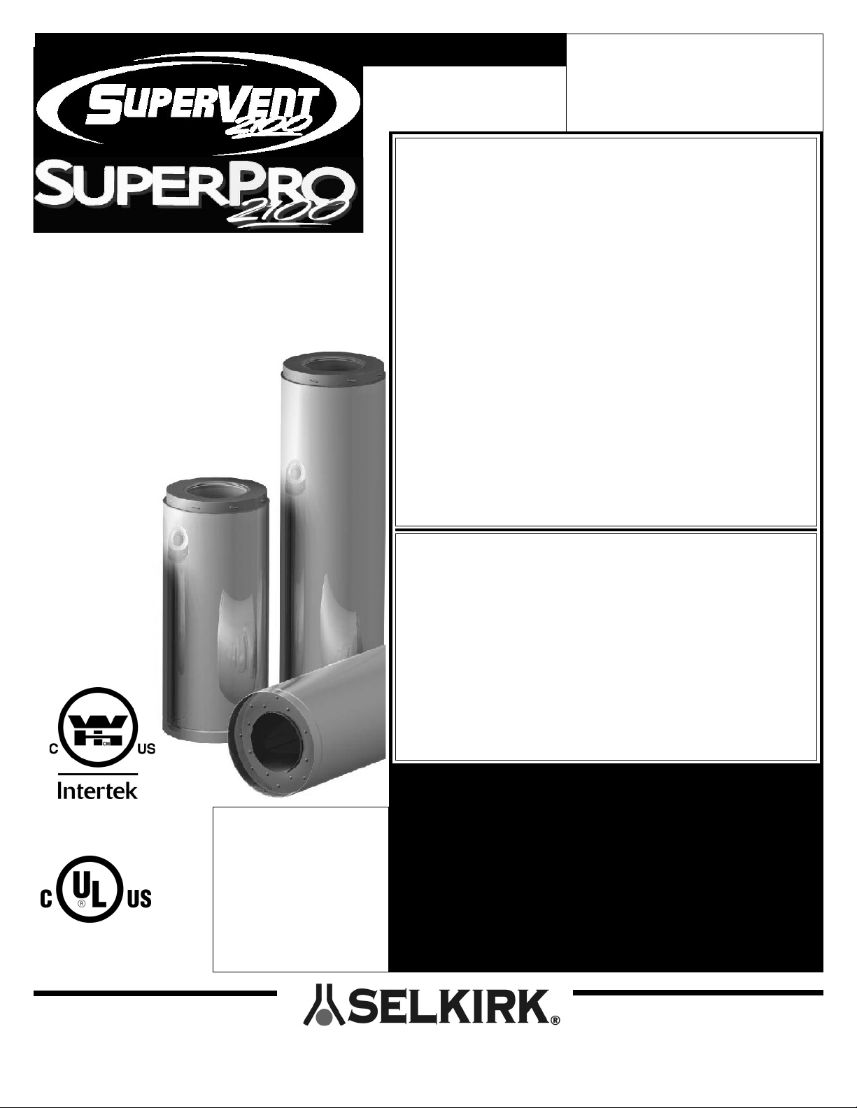
Authorities require that the chimney extend not less than 3 ft
(900 mm) above the highest point where it passes through the
roof of a building and not less than 2 ft (600 mm) above any
portion of the building within 10 ft (3m). See Figure 1and Chart
2 on page 20 of these instructions.
3ft.(900mm)
min.
3ft.(900mm)
min.
2 ft.
(600mm)
2 ft.
(600mm)
10 ft.
(3m)
The use of Locking Bands at all chimney joints is recommended for
added safety and stability when exposed to high winds and as a
precaution against accidental unlocking of lengths when the system
is inspected and swept.
Do not install the chimney directly at the outlet of the appliance.
Interconnectingstovepipe is requiredunless the applianceis specifi-
cally approved for that type of installation.
Use only with an appliance listed by a recognized testing authority
such as CSA, Underwriters Laboratories Inc., Underwriters Labora-
tories of Canada or Intertek Testing Services/Warnock Hersey.
Do not mix and match with other manufacturer's products. Use only
Selkirk's Models JM/ALT listed components.
TOOLS
Your model JM/ALT chimney system is designed for installation
using standard building materials and procedures. The following
tools/equipment may be required as well as some others depending
on the location and structure in which the chimney is to be installed:
FIGURE 1
-Screwdrivers and pliers
-Plumb line and level
-Square
-Keyhole saw or power jig saw
-Caulking gun
-Safety gloves
-Safety goggles
-Hammer and nails
-Tin snips
-Tape measure
WEAR SAFETY GLOVES WHEN HANDLING
SHEET METAL PARTS WITH SHARP EDGES
CHIMNEY SIZING:
In order to achieve safe, optimum performance of the appliance,
service life of the chimney, the chimney must be sized correctly for
the connected appliance. In general, the chimney flue should be the
same size as the appliance flue outlet. The installation should be
done in accordance with the applicable installation codes (eg. CAN/
CSAB149, CAN/CSAB139, NFPA54and NFPA31) andappliance
manufacturer instructions. Plan the installation of your appliance
andchimney in sucha waythat both yourchimney andflue pipe runs
are as short and straight as possible. By having too long and/or
multiple bend installations you can reduce the system draft which
can affect the operation, and/or performance of your appliance and/
or chimney system.
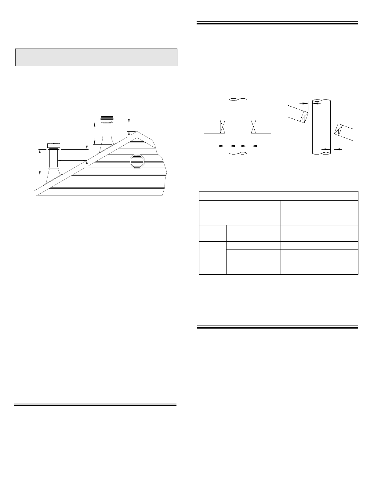
Plan your installation carefully. If possible, position the stove so
that the flue outlet is centered between joists or rafters. Drop a plumb
line to the center of the flue outlet and mark this center point on the
ceiling. Layoutandframeinall openingsensuringthespecified 2"(50
mm) clearance to combustibles is maintained. Refer to Table 1 and
applicable Tables for framing dimensions and mark the appropriate
cutting lines around the center point. All openings should be square,
plumb and in perfect alignment with each other (see figure 2).
For sloping roofs (cathedral/vaulted ceiling), ensure that the framing
dimension is measured in the horizontal plane (see figure 3).
FRAMING DETAILS
* The clearance to combustibles obtained with a correctly installed
Decorator Ceiling Support or Wall Thimble in the framed opening
specified has been tested. The 2" clearance does not apply at these
locations. When cutting the inside "finished" surface of your wall or
ceiling cut a "round hole" to the framing dimension in Table 1.
To complete a proper Decorator Ceiling Support installation, the
following parts may be required:
-Decorator Ceiling Support (DCS): Required when supporting a
chimney through a flat level ceiling.
- Stove Pipe Adaptor (ASE): Transition from the chimney to flue pipe.
- Attic Insulation Shield (AIS): Required where a chimney passes
from a lower living space into an upper living or an attic space.
- Universal Shielding Insulation (JUSI): To reduce cold air infiltra-
tion into the dwelling when installed in conjunction with the Attic
Insulation Shield.
- Rafter Radiation Shield (RRS): Required when the chimney is
enclosed immediately below the roof line.
-Roof Flashing Assembly(IncludingStorm Collar): Requiredwhen
the chimney penetrates a roof.
INSTALLATION PROCEDURES
FIGURE 3
Typical Roof
Joist Framing
FIGURE 2
Typical Joist
Framing
*Decorator
Ceiling
Support
*Wall
(Support)
Thimble
Framing Dimensions Table
All Other
Framing
Chimney Flue
Diameter
TABLE 1
DECORATOR CEILING SUPPORT (DCS)
in.
in.
in.

6
ATTIC INSULATION SHIELD (AIS)
Single Story Installation
Unenclosed
Attic Space
Roof Joist
Rain Cap
Storm Collar
Ventilated Flashing
Attic Insulation Shield
Decorator Ceiling Support
Chimney Section
Stove Pipe Adapter
Ceiling Joist
(Framed all 4 sides)
FIGURE 5
Install additional chimney sections and lock together by turning
clockwise until the two sections lock together snugly. Even though
Locking Bands are optional, it is always recommended to install a
Locking Band to secure the two chimney sections. Continue adding
chimney lengths until a height of about 2 ft. below the next ceiling
level is achieved.
NOTE: The Decorator Ceiling Support cannot be used when the
chimney terminates in a room with a suspended ceiling. When false
ceiling are encountered, use a Cathedral Ceiling Support to extend
into the room below the finished ceiling. The floor/ceiling joist must
beframed onall4 sides. Theboxmust extendaminimum of1"below
thesuspended ceiling. The chimneylength is toprotrude aminimum
of 3" below the support and the trim angles must be installed.
An Attic Insulation Shield must be installed where a chimney passes
from a lower living space into an upper living space or into an attic
space. It is designed to keep insulation materials from coming into
contact with the chimney and will protect up to a 10" (250 mm)
thickness of insulation. The height of the Attic Insulation Shield is to
meet the insulation level requirement of the National Building Code.
Whereheightrestrictions willnotpermit theuseof theAtticInsulation
Shield, it is permissible to construct an enclosure with the required air
spaceclearanceto theouterpipe alltheway totheunderside oftheroof
deck. Allchimneyenclosuresmustmaintaintherequiredminimumair
space clearance of 2" (50mm) to the chimney. When enclosing the
chimney below the roof line, a Rafter Radiation Shield (RRS) must be
installed at the roof level (see Figures 6a and 21).
For a proper installation, the opening must be fully framed at
2 inches of clearance to the ouside casing of the chimney with
framing material of the same dimension as the ceiling or floor joist
as per the Framing Dimensions in Table 1.
The Decorator Ceiling Support will support up to 40 ft. (13 m) of
chimney sections, all of which must be installed above the support.
Figures 5 & 6 show the 2 most common types of Decorator Ceiling
Support Installation. Frame (on all 4 sides) a level square opening
with the inside dimensions of 14-3/8" (365mm) square. Remember
to cut a round hole on the finishing (gyprock) side.
Slide the Trim Ring (Finishing Plate) onto the Decorator Ceiling
Support and position the assembly into the framed opening from
below. Ensure that the Finishing Plate is flush with the underside of
the ceiling and the assembly is level and plumb. Secure in place with
3 x 6d (2”) nails or #8 x 1-1/2" wood screws through each of the 4
straps.
-Suitable Lengths ofChimney : Thechimney diameter shouldbe sized
to suit the appliance.
- 15o30° or 45 Chimney Elbow Kit : To avoid cutting of joists and clear
other obstructions. Kit includes: 2 Elbows, 1 Offset Support and 4
Locking Bands.
-Rain Cap: Toprevent rainand/or debrisfromentering inthe chimney.
Standard or Deluxe model.
The crimped end (stub) of the Stove Pipe Adapter is intended to fit
inside of the flue pipe from a solid fuel appliance, thus preventing
condensate drips at the chimney connection.
Install inter-connecting flue pipe following the appliance
manufacturer’s installation instructions and appropriate building
coderequirements andthe InstallationCodeB-365, keeping inmind
that the flue pipe run should be as short and straight as practicable.
Generally, for a wood burning appliance installation, an 18” mini-
mum clearance to combustibles must be maintained for a single wall
flue pipe. The exception to this is a double wall stove pipe, such as
Selkirk'sModelDSP which can beinstalled atreduced clearances to
combustibles. Seeseparate installationinstructionsfor moredetails.
Stove Pipe
Adapter (ASE)
Decorator
Ceiling
Support
Chimney
Length
STOVE PIPE ADAPTER (ASE)
TheStove PipeAdapter(ASE) isinstalled bytwist-lockingit intothe
bottom end (female end) of the first Chimney Section that enters the
Ceiling Support. Do not install an elbow in the Ceiling Support.
Make sure that the male coupler of the insulated Chimney Length is
pointing upwards as indicated by the arrow on the chimney label.
Lower the assembly down into the Decorator Ceiling Support
ensuringthat theStovePipe Adaptersleeve isprotrudingthrough the
support and into the living space (see Figure 4).
FIGURE 4

7
When installing the Attic Insulation Shield above the Decorator
Ceiling Support as shown in Figure 5, be certain that the base of the
shield is flush with the top of the joist framing and nail in place using
1” spiral nails or #8 x 1" wood screws.
NOTE: To reduce cold air infiltration into the dwelling you
can install the optional Universal Shielding Insulation (JUSI)
into the Attic Insulation Shield. See separate installation
instructions packaged with the JUSI.
Wheninstallingthe AtticInsulationShield wherethechimneypasses
from a living space to an enclosed attic space, as shown in figure 6,
or between floors, install the shield from below and nail in place
using 1” spiral nails or #8 x 1" wood screws. A Rafter Radiation
Shield is required at the roof level when the chimney is enclosed
below the roof line.
At the level where the chimney penetrates the air/vapour barrier,
special attention is required. Seal the vapour barrier to the Support
or Attic Insulation Shield or Wall Thimble using an appropriate
caulking compound as per the requirement of local authorities.
If insulation is blown in the attic and adheres to the chimney pipe, it
must be brushed off to eliminate any possible contact of this material
with the chimney surface.
Two Story Installation
(Enclosed Attic)
FIGURE 6a
Enclosure
Enclosed
Attic Space
Living Space
Rafter Radiation Shield
Ventilated Flashing
Decorator Ceiling Support
Stove Pipe Adapter
Enclosure
Chimney Section
Rain Cap
Roof Joist
Storm Collar
Attic Insulation Shield
Floor, Ceiling Joist
(Framed all 4 sides)
Ceiling Joist
(Framed all 4 sides)
Two Story Installation
Alternate Enclosed Attic with Firestop Spacer
Enclosure
Enclosed
Attic Space
Living Space
Enclosure
Ventilated Flashing
Decorator Ceiling Support
Chimney Section
Rain Cap
Roof Joist
Storm Collar
Firestop Spacer
Floor, Ceiling Joist
(Framed all 4 sides)
Ceiling Joist
(Framed all 4 sides)
Rafter Radiation Shield
FIGURE 6b
An alternate method can be used instead of the standard Attic
Insulation Shield (AIS), under the following circumstances:
When the chimney is enclosed in the attic space below the
roofline - FIGURE 6b:
- Wherethe chimneyin theatticspaceisenclosed, youcan substitute
the Attic Insulation Shield (AIS) with the Firestop Spacer (FS)
installed at the ceiling level (see Figure 6b).
- Install the Rafter Radiation Shield at the roof level (see Figure 6b).
- The enclosure must maintain the required minimum air space
clearance of 2" (50mm) to the chimney.
ATTIC INSULATION SHIELD
ALTERNATE METHOD
When the chimney passes from a living space to a living space or
into an attic space - FIGURE 6c:
- Where the chimney passes from a lower living space into an upper
living space, install the Firestop Spacer (FS) at the ceiling level (see
Figure 6c).
- Where the chimney passes from a lower living space into an attic
space,the FirestopSpacer (FS)is installedattheceilinglevel andthe
Attic Insulation Shield with Dropdown Shield (AISD) is installed
flush with the top of the attic joist framing and fixed in place (see
Figure 6c). NOTE: When the Firestop Spacer is used the Attic
InsulationShield withDropdown Shield (AISD)must beinstalled in
an open attic space.
SeeFigure 7bforframing dimensionsofthe FirestopSpacer (FS)and
the Attic Insulation Shield with Dropdown Shield (AISD).

8
45° ELBOW INSTALLATION
One pair of (two) 45° elbows may be used in an interior installation
toprovide anoffsetin orderto avoidcuttingof joistsandto clearother
obstructions. The vertical run of chimney above an offset must be
supported with an elbow support. Each elbow support will support
15 ft. (4.5 m) of chimney and the maximum length of chimney
allowedbetweentheelbowsis 6'(2m). Elbowkits contains2Elbows,
4 Locking Bands, an Elbow Support and 1 Corner Shield Plate and
supplied hardware pack (4 - #6 x 1" screws).
When using 45° elbows, special components are required:
- Firestop Spacer at all ceiling level in the system (FS - sold
separately) see Figures 7b, 7d and 7e.
- Corner Shield Plate (included with 45° Elbow Kits) see Figures 7c,
7d and 7e.
- Attic Insulation Shield with Dropdown Shield (AISD - sold
separately), isinstalled flushwiththe topofthe atticjoistframing and
fixed in place (see Figures 7b, 7d and 7e).
Basement of a Two Story Installation
Alternate Firestop Spacer at Ceiling Levels
FIGURE 6c
Enclosure
Unenclosed
Attic Space
Living Space
Firstop Spacer
Ventilated Flashing
Decorator Ceiling Support
Chimney Section
Rain Cap
Roof Joist
Storm Collar
Attic Insulation Shield with
Dropdown Shield (AISD)
Floor, Ceiling Joist
(Framed all 4 sides)
Ceiling Joist
(Framed all 4 sides)
position the Elbow in the required direction. Fasten the Elbow to the
chimney Length with the supplied Locking Band.
Place the required offset chimney Length(s) as per the Offset Chart
1 (page 19) for appropriate length(s). Turn it clockwise to lock it in
place and secure with the supplied Locking Band.
Install the remaining offset Elbow to turn the chimney back to the
vertical position and fasten in place with the supplied Locking Band.
During installation provide supplementary support for the offset
section to avoid undue stress on connected elbows.
Installan ElbowSupport onthe Lengthjust abovethehighest Elbow.
Attach the Support Band to the chimney with 4 nuts and bolts, and
then install four stainless steel sheet metal screws through the pre-
punched holes. Attach the Support Straps to the Support Band
assembly and nail the Support Straps to the framing using 6d (2”)
nails or #8 x 1-1/2" wood screws (see Figure 7a).
FIGURE 7a
Storm Collar
Roof Joist
Attic space
Rain Cap
Attic Insulation Shield
Elbow Support Bands
Ventilated Flashing
Elbow
Locking Bands
Decorator Ceiling Support
Offset (Elbow) Installation
Elbow
Floor, Ceiling Joist
(Framed all 4 sides)
Enclosure
Stove Pipe Adapter
Locking Bands
Ceiling Joist
(Framed all 4 sides)
Elbow Support Straps
Chimney Section
Enclosure
Living Space
Firstop Spacer
Chimney Section
Ceiling Joist
(Framed all 4 sides)
One pair of (two) 15o, 30o or 45° elbows may be used in an interior
installation to provide an offset in order to avoid cutting of joists and
to clear other obstructions. The maximum permissible angle with
solid fuel installation is 45 degrees. NOTE: See separate section
for 45° elbow (pages 8 & 9). The vertical run of chimney above an
offset must be supported with an elbow support. Each elbow support
will support 15 ft. (4.5 m) of chimney and the maximum length of
chimney allowed between the elbows is 6' (2m). Refer to the Offset
Chart 1 on page 19 in these instructions for more details. Elbow kits
contains 2 Elbows, 4 Locking Bands and an Elbow Support.
The female end of the Elbows are not embossed, this ensures proper
alignmentof thechimneysystem ismaintained. LockingBands must
be installed at all chimney joints forming an offset.
Install the insulated offset Elbow on the vertical chimney length and
ELBOW INSTALLATION
Never install an elbow in a joist area. Chimney lengths must
pass vertically through framed joist areas.

9
13"
4"
4"
6"
14" X 14" 7"
15" X 15" 8"
16" X 16"
The female end of the Elbows are not embossed, this ensures proper
alignment of the chimney system is maintained. Locking Bands must
be installed at all chimney joints forming an offset.
Install the insulated offset Elbow on the vertical chimney length and
position the Elbow in the required direction. Fasten the Elbow to the
chimney Length with the supplied Locking Band.
Place the required offset chimney Length(s) Turn it clockwise to lock
it in place and secure with the supplied Locking Band.
Install the remaining offset Elbow to turn the chimney back to the
vertical position and fasten in place with the supplied Locking Band.
45° OFFSET CORNER SHIELD PLATE
FIRESTOP SPACER:
Ateach levelwherethe chimneypasses throughthedwelling, install
a Firestop Spacer at each ceiling levels. See Figures 7b, 7d & 7e.
CORNER SHIELD PLATE:
In the Offset Enclosure, the Corner Shield Plate is to be installed at
the top corner of the enclosure where it comes to a point. Figures 7c,
7d and 7e. The wider 13" dimension is installed horizontally. Bend
on the 8" width. Fasten with supplied screws at each outmost
corners.
Storm Collar
Roof Joist
Attic space
Rain Cap
Attic Insulation Shield with
Dropdown Shield (AISD)
Elbow Support Bands
Ventilated Flashing
Elbow
Locking Bands
Elbow
Floor, Ceiling Joist
(Framed all 4 sides)
Enclosure
Corner Shield
Plate
Ceiling Joist
(Framed all 4 sides)
Elbow Support Straps
Firestop Spacer
MAIN FLOOR OF A 2 STORY INSTALLATION - 45° OFFSET
BASEMENT OF A 2 STORY INSTALLATION - 45° OFFSET
At the attic level, an Attic Insulation Shield with Dropdown Shield
(AISD) needs to be used in conjunction with the Firestop Spacer
insalled at the ceiling level.
If the 45° offset are installed in the attic space and they are not enclosed,
the Corner Shield Plate is not to be used.
2nd Floor
Stove Pipe Adaptor
Locking Bands
Decorative Ceiling Support
Storm Collar
Attic space
Rain Cap
Attic Insulation Shield with
Dropdown Shield (AISD)
Elbow Support Bands
Ventilated Flashing
Elbow
Locking Bands
Elbow
Floor, Ceiling Joist
(Framed all 4 sides)
Enclosure
Corner Shield
Plate
Ceiling Joist
(Framed all 4 sides)
Elbow Support Straps
Firestop Spacer
2nd Floor
Stove Pipe Adaptor
Locking Bands
Decorative Ceiling Support
Enclosure
Lengths
Firestop Spacer
During installation provide supplementary support for the offset
section to avoid undue stress on connected elbows.
Install an Elbow Support on the Length just above the highest Elbow.
Attach the Support Band to the chimney with 4 nuts and bolts, and then
install four stainless steel sheet metal screws through the pre-punched
holes. Attach the Support Straps to the Support Band assembly and nail
the Support Straps to the framing using 6d (2”) nails or #8 x 1-1/2" wood
screws (see Figures 7d & 7e).
FIGURE 7d
FIGURE 7e
Bend plate so dimpled screw holes
are against framing material
Secure plate to framing with the
supplied #6 x 1" screws at each
outmost corners
Exterior
of
enclosure
Interior of
enclosure
#6 x 1"
Screws
FIGURE 7b
TOPVIEW OF
FIRESTOP SPACER
BOTTOMVIEW OF
FIRESTOP SPACER
Firestop Spacer (FS) and Attic Insulation Shield with
Dropdown Shield (AISD) Framing Dimensions
FRAMING DIMENSIONS
FIGURE 7c
Outmost
corners
See Figure 7b for framing dimensions of the Firestop Spacer (FS) and
Attic Insulation Shield with Dropdown (AISD).

10
WALL SUPPORT (AWS) - 2-1/2" only
Aspreviously mentioned, theideallocation foryourchimney system
is within the building envelope. A Wall Support installation is
required when the above mentioned location is not possible.
To complete a proper Wall Support installation, the following parts
may be required:
- Adjustable Wall Support (AWS): Intended for a through-the-wall
installation where the chimney has a horizontal connection. The
AWS is adjustable only from 2" to 2-1/2" from the vertical wall.
NOTE: The AWS is supplied in the Wall Support Kit. For greater
adjustment, the WS must be ordered separately.
Stove Pipe Adaptor (ASE): Transition from chimney to connector.
- Roof Flashing Assembly: Required when the chimney penetrates
a roof or a roof overhang.
- Rafter Radiation Shield (RRS): Required when the chimney is
enclosed immediately below the roof.
- Wall Band (WB): Required to provide lateral support to the
chimney.
-Suitable lengthsofchimney:The chimneydiameter shouldbe sized
to suit the appliance.
-Wall Thimble (WT): Required to pass through a combustible wall.
- Universal Shielding Insulation (JUSI): To reduce cold air infiltra-
tion into the dwelling when installed in conjunction with the Wall
Thimble.
- Rain Cap: To prevent rain and/or debris from entering in the
chimney. Standard or Deluxe model.
The Adjustable Wall Support will support up to 33 ft.
(10 m) of chimney, all of which must be above the support, with the
exception of the 1 foot chimney section and/or an Insulated Tee
Plug, which is installed below the support.
If the total chimney height exceeds the Adjustable Wall Support
limitation, an Adjustable Intermediate Wall Support (AIWS) must
be installed. See the AIWS section for more details.
Wall Support (AWS) Installation
Rain Cap
Storm Collar
Wall Band
Locking Band
Insulated Tee
Wall Support
1 Foot Chimney Section
and/or
Insulated Tee Plug
3" Minimum
Chimney Section
Stove Pipe Adapter
Wall Thimble
Inner Half
Wall Thimble
Outer Half
Ventilated Flashing
8 Feet
(Max)
FIGURE 8
Tee Plug
Female Coupler
(Down)
FIGURE 10
Nut
Side Bracket
Side Bracket
Installtheinnerhalf(withroundplate) oftheWallThimbleintheinside
wall surface, ensuring that the shield slides over the shield of the outer
half. Once in place and flush against the wall, install the trim plate and
fasteninplacewith appropriatefastenersthroughthe fourpre-punched
holes (see Figure 9).
AssembletheWallSupport (Figure10)by attachingthe2sidebrackets
(point of triangle facing down) to the support plate with the hardware
supplied. Ensure that the female coupler attached to the underside of
the support plate is facing down. For an ajustment of the support plate,
align the fixed holes on the support plate with the elongated holes on
the side brackets.
Adapter Ring
Bolt
Support Plate
Determine the center line of the horizontal connection (length through
the wall) and frame an opening to the dimensions specified in the
Framing Dimension Table 1. (For non-combustible walls (concrete
block or poured foundation), cut a hole 3/16" greater than the outside
diameter of the chimney). Install the outer half (with square plate) of
the Wall Thimble in the outside wall surface. Secure in place using
appropriate fasteners using all of the pre-punched holes.
Telescoping adjustment
from 4-1/2" to 8-3/4"
Interior Inner Half
of Wall Thimble
Black Finishing
Round Plate
Exterior Outer Half
of Wall Thimble
FIGURE 9
Wall Thimble
NOTE: To reduce cold air infiltration into the dwelling you
can install the optional Universal Shielding Insulation (JUSI)
into the Wall Thimble. See separate installation instructions
packaged with the JUSI.
Install an appropriate Insulated Chimney Length such as a one foot
section (or longer if required - not to exceed 24 inch) to the horizontal
branch of the Insulated Tee. Lock securely into the tee branch by
twisting clockwise. A Locking Band must then be installed at this
connection. Make sure the nut and bolt are facing down to prevent any
water from collecting in the locking band.The Tee branch extension
must protrude a minimum of 3" (75 mm) into the room (Fig. 8).

11
FIGURE 11
WALLSUPPORT (WS) -Adjustable up to 6"
from a vertical wall (sold separately)
Aspreviously mentioned,the ideal locationfor yourchimney system
is within the building envelope. A Wall Support installation is
required when the above mentioned location is not possible.
To complete a proper Wall Support installation, the following parts
will or may be required:
- Wall Support (WS): Intended for a through-the-wall installation
where the chimney has a horizontal connection. The WS is
adjustable from 2" to 6" from the vertical wall. NOTE: The WS
is NOT supplied in the Wall Support Kit. Must be ordered
separately.
- Stove Pipe Adaptor (ASE): Transition from chimney to flue pipe.
- Insulated Tee (IT) with Insulated Tee Cap (TPI): Allowing a
horizontal connection to the chimney.
- Roof Flashing Assembly: Required when the chimney penetrates a
roof or a roof overhang.
- Rafter Radiation Shield (RRS): Required when the chimney is
enclosed immediately below the roof.
- Wall Band (WB): Required to provide lateral support to chim-
ney.
- Suitable Lengths of Chimney: The chimney diameter should be
sized to suit the appliance.
- Chimney Length: Appropriate length for connection to Tee branch.
- Wall Thimble (WT): Required to pass though a combustible
wall.
- Rain Cap: Standard or Deluxe model
Themaximumchimney height aboveaWallSupport isindicatedinTable
2 and illustrated in Figure 11, all of which must be above the support.
The Wall Support will allow for an adjustment of 2" to 6" from a
vertical wall. Threaded studs are factory installed on both side
brackets and the support plate for fast and easy assembly (see
Figure 14).
Ensure the Wall Support Brackets are bolted securely to the wall.
Rain Cap
Storm Collar
Wall Band
Locking Band
Insulated Tee
8 Feet
(Max)
3" Minimum
Chimney Section
Stove Pipe Adaptor
Wall Thimble Inner Half
Wall Thimble Outer Half
Ventilated Flashing
Support Bracket
Support Plate
Lag Screws into Structure
"D"
Distance
from Wall to
Chimney
(2" minimum
or as per
Table 4)
"H"
Max.
Chimney
Height
(See Table 2)
See Table 2 for maximum Chimney Heights based
on Chimney Diameter and Distance from Wall
Install a Wall Band midway up the first chimney length above the
Insulated Tee. Wall bands must then be installed at 8 ft. (2.4 m)
intervals above this point (see fig. 8). Secure the wall band bracket
tothe wallusingtwo 6d(2”)spiral nailsor woodscrews. Forconcrete
walls use suitable masonry fasteners.The nut and bolt supplied will
fasten the band around the chimney.
If the chimney penetrates an overhang (soffit) cut an opening with 2"
(50 mm) clearance all around and install an Attic Insulation Shield if
space permits on the under side of the overhang. If it is not possible
the overhang area can be enclosed and a Rafter Radiation Shield
installed at the roof level and a Finishing Plate installed from below.
If the attic is open to the overhang, close off the access with suitable
buildingmaterials ensuringthat a2" (50 mm)air spaceis maintained.
From above install a Roof Flashing and Storm Collar by following
theRoof Flashingsection intheseinstructions. If theoverhangis not
deep enough to allow the chimney to be fully installed within the
overhang, it will be necessary to cut into it. Ensure that a 2" (50 mm)
clearance all around the chimney is respected. Framing and flashing
the sides of the opening will be required. Install a Wall Band at this
level.
NOTE: Interior chimneys installed with a Wall Support must use an
Attic Insulation Shield (AIS) when extending through floor/ceiling
joist and into attic space.
Slide the assembled AIWS over the protruding length of chimney.
Fasten the AIWS to the wall using four 1/4” by 2” wood screws
through the pre-punched slots in each bracket. Install the draw band
around the protruding chimney length securely against the support
plate with the supplied nut and bolt. Install four stainless steel sheet
metal screws through the pre-punched holes in the draw band. Cover
the heads of the screws with a non-hardening waterproof caulking.
If the total chimney height exceeds the wall support limitations, an
Adjustable Intermediate Wall Support (AIWS) must be installed.
Use of an AIWS will support another 33 ft. (10 m) of chimney. The
AIWS is adjustable only from 2" to 2-1/2" from the vertical wall.
ADJUSTABLE INTERMEDIATE WALL SUPPORT
(AIWS)
From outside the building, slide the chimney length (previously
installed on the tee branch) through the Wall Thimble ensuring the
male coupler of the tee is facing upward. Place the adapter ring
(Figure10) onthe wallsupport sothat thesleeve onthe adapterdrops
through the hole in the support plate. Place the assembled wall
support against the wall (plate up) directly below the tee. Slide the
assembled wall support up to the tee ensuring that the adapter on the
wall support engages with the female coupler of the tee. Ensure the
wall support is level, and secure to the wall with four 1/4” by 2” lag
bolts through the pre-punched slots in each bracket or suitable
masonry fasteners for a concrete block or poured foundation wall. If
the support is properly positioned, these lag bolts will also go into
wall studs placed on 16” (405 mm) centers.
NOTE: THE CHIMNEY MUST EXTEND AT LEAST
3” (75 MM) INTO THE LIVING SPACE WHERE THE
STOVE PIPE ADAPTER WILL BE ATTACHED TO THE
CHIMNEY BRANCH.
Use a non-hardening high-temperature silicone caulking to seal
around the horizontal chimney length where it enters on the exterior
of the Wall Thimble or a concrete wall.
NOTE: Ensure that you have set aside the Tee Plug, if not, do so
now as you will require it later.
NOTE: If a greater adjustment is required, such as to clear an
overhang, the WS Wall Support must be installed-ordered sepa-
rately.

12
10-3/16" 11-3/16" 12-3/16"
14-3/8"
x
14-3/8"
6" 7"
8"
11-1/4" 12-1/4" 13-1/4"
A
B
A
B
Section
14-3/8"
x
14-3/8"
14-3/8"
x
14-3/8"
2
2.5
3
3.5
4
4.5
5
5.5
6
34
33
32
31
30
28
26
23
21
29
28.5
28
27
26
24
23
21
18
26
25.5
25
24
23
22
20
18
16
The following steps will assist you in the installation of the Wall
Thimble and of the Wall Support. Figure 11 shows a typical Wall
Support installation through a combustible wall.
Distance
from Wall to
Chimney 6” ID
Chimney
7” ID
Chimney
8” ID
Chimney
H(feet)
Max. Height
H (feet)
Max. Height
H (feet)
Max. Height
D (inches)
Wall/Chimney
Table 2 - Wall Support
Chimney Height Chart
D- Distance from wall to the chimney
H - Height of chimney in feet
See Figure 8 also.
1. Determine the centre line of the horizontal connection (Chimney
Length through the wall) and frame an opening to the dimensions
specified for the Wall Thimble in a combustible wall (see Section A
in Table 3 and Figure 13-A).
- Use a stud finder to roughly locate the walls studs. Mark the
outline of the hole and drill a pilot hole in its center.
3. After framing in your opening to the dimensions specified to the
Framing Tables 1 or 3, install the outer half (with the unfinished
square plate) of the Wall Thimble into the outside wall opening.
Secure in place with appropriate fasteners through the pre-punched
holes.
2. For a non-combustible wall (concrete block or poured
foundation), cut a hole (3/16”) greater in diameter than the outside
diameter of the chimney as per Table 3.
NOTE: When cutting the inside "finished" surface of your wall cut
a "round hole" to the framing dimension in Table 3.
- Break out part of the wall covering within the outline to confirm
that the hole will be centered between studs and that no electrical
wires could be cut by the saw.
Wall Thimble
Black
Finishing
Round Plate
Interior Inner
Half of Wall
Thimble
Exterior Outer
Half of Wall
Thimble
Figure 12
Telescoping adjustment
from 4-1/2” to 8-3/4”
NOTE: To reduce cold air infiltration into the dwelling you
can install the optional Universal Shielding Insulation (JUSI)
into the Wall Thimble. See separate installation instructions
packaged with the JUSI.
4. Install the inner half (with round plate) of the Wall Thimble into
the inside wall opening, ensuring that the shield slides over the shield
of the outer half. Once in place and flush against the wall, install the
black finishing trim plate onto the wall surface and fasten in place
with appropriate fasteners through the 4 pre-punched holes.
Two options are described below for the installation of the Wall
Support and the Insulated Tee assembly. Follow Method A if
insertingan assembledInsulated ChimneyLength andInsulated Tee
into the Wall Thimble prior to the Wall Support. Follow Method B
if securing of the Wall Support to the wall prior to the Insulated Tee
and the Insulated Chimney Length.
METHOD A
6. Install an appropriate Insulated Chimney Length such as a one
foot section (or longer if required-not to exceed 24 inches) to the
horizontal branch of the Insulated Tee. Lock securely into the Tee
branch by twisting clockwise. A Locking Band must then be
installed to secure the connection. Make sure the nut and bolt are
facing down to prevent any water from collecting in the Locking
Band. The Tee branch extension must protrude a minimum of 3"
into the room.
5. Assemble the 2 side Brackets (point of triangle facing down) to
the Support Plate (flange up and threaded stud towards the wall) by
inserting the threaded studs into the oblong slots (see Figures 14 &
15). Install the supplied nuts on the threaded studs until snug, do not
tighten at this time as adjustments may be required. Set aside and
prepare the support bracing to secure the side brackets as per the
Framing Dimensions in Section B of Table 3 and Figure 13 (B).
7. From outside the building, slide the assembly (Chimney Length
installed on the Tee Branch) through the Wall Thimble ensuring the
male coupling on the Tee is facing upward. The Wall Thimble will
provide support until you are ready to install the Wall Support
Assembly.
8. Place the assembled Wall Support against the wall (Support Plate
Flange up) directly below the Insulated Tee. Slide the Wall Support
up to the bottom of the Insulated Tee ensuring that the flange on the
top of the Support Plate is inserted into the female coupler.
Table 3 - Framing Dimensions Wall
Thimble & Support Brackets
WallThimble
MinimumFramedOpening
forCombustible Wall
MinimumRoundHole
Diam.ForNon-CombustibleWall
Support Brackets
MinimumFramedOpening
ForBracing
ChimneySize(ID)
Figure 13

13
Support Side
Brackets
Support Bracket
Threaded Stud
Nut
Support
Plate
Nuts
Nut
Support Bracket
Threaded Stud
Support
Plate
Threaded
Stud
(toward
wall)
FIGURE 14 - UNDERSIDE VIEW OF THREADED STUDS
AND NUTS
Slot for Tee Cap Bracket
Support Plate
Threaded Stud
(toward wall)
NOTE: THE CHIMNEY LENGTH MUST EXTEND AT LEAST
3” THROUGH THE WALL INTO THE LIVING SPACE WHERE
THE STOVE PIPE CONNECTOR WILL BE
ATTACHED TO THE CHIMNEY BRANCH.
9. Priorto securing ensurethat theInsulated Tee assembly isplumb
and level and sitting flush on the Support Plate. Secure to the wall
through the pre-punched holes located on each side of the Wall
Stud and Nut
located to front
of Support
Bracket
Support
Brackets
Threaded
Stud
and Nut
located at rear
of Support
Plate
Pre-
Punched
Holes of
Support
Bracket
Flange Up
FIGURE 15 - FRONT VIEW OF WALL SUPPORT ASSEMBLY
Support Plate
Slot for Tee Cap
Bracket
Insulated
Tee
Support Plate
METHOD B
11. Position the Wall Support so that the Insulated Tee will be
centered inside the Wall Thimble. Ensure that the Wall Support is
level, and secure to the wall through the pre-punched holes located
on the sides of each of the support brackets using (8) #14 x 1-1/2"
hex head lag screws or #10 x 1-1/2" wood screws. You can drill 5/
32" pilot holes for the lag screws. Make sure they go into solid
bracing as per the requirements in Table 3 Section B and Figure 13
(B) below the prepared Wall Thimble opening. For concrete block
or poured foundation use suitable fasteners.
12. Place the Insulated Tee on the support Plate ensuring that the
male coupler of the Tee is facing up and the flange on the top of the
Support Plate slides into the female coupler (see Figures 16 & 17).
Insulated Tee Cap
Tee Cap
Bracket
Securing
Screw
FIGURE 17 - Assembled Wall Support
with Tee Cap Secured in Place
FIGURE 16 - Explosion View - Wall Support, Insulated
Tee and Tee Cap, Tee Cap Bracket and securing Screw.
10. Position the Support Plate to the desired distance from the wall
as per the limits shown in Table 2 and Figure 11. Tighten the 4 nuts
onto the threaded studs. Proceed to Step 14.
Support Brackets using (8) #14 x 1-1/2" hex head lag screws or #10
x 2" wood screws. Make sure they go into solid bracing as per the
requirements in Table 3 Section B and Figure 13 (B), below the
prepared Wall Thimble opening. You can drill 5/32" pilot holes. For
concrete block or poured foundation use suitable fasteners.
13. From inside the building, slide an appropriate Insulated
ChimneyLength suchasa onefootsection (orlongerifrequired- not
to exceed 24 inches) through the Wall Thimble to the horizontal
branch of the Insulated Tee. Lock securely into the Tee branch by
twistingclockwise. A LockingBandmust thenbe installedtosecure
the connection. Make sure the nut and bolt are facing down to
prevent any water from collecting in the Locking Band. The Tee
Branch extension must protrude a minimum of 3" into the room.

14
WARNING: TheInsulated TeeCap mustbe installedandsecured
in place. Failure to install could cause fire, injury or death.
Insulated
Chimney
Sections
Support
Plate
Insulated Tee Cap
Nutsert
Screw to
Secure Tee
Cap Bracket
Tee Cap
Bracket
15. Insert the Insulated Tee Cap into the bottom of the Support Plate
opening and secure by sliding the Tee Cap Bracket into both slots
located at the front and rear of the Support Plate. Make sure the Tee
Cap Bracket is beneath the Tee Cap and the other end is exiting
through the slot at the back of the Support Plate. Secure in place by
threading the securing screw into the nutsert located on the front of
the Support Plate (Figures 16, 17 and 18).
FIGURE 18 - Securing of Insulated Tee Cap
14. Use a non-hardening high-temperature sealant (500° F) to seal
around the horizontal Chimney Length where it enters through the
exterior of the Wall Thimble or the concrete wall.
Nuts
Slot on
Support
Bracket
Support Brackets
Pre-Punched
Holes of Support
Bracket
Support Plate
w/ Flange Up
Slot for Tee Cap
Bracket
Slot on
Support
Plate
Bolts
FIG. 20- SLOT AREAS
WITH BOLTS (#8 x 3/4")
AND NUTS ASSEMBLY
OF SUPPORT BRACK-
ETS AND SUPPORT
PLATE
FIG. 19- FRONT VIEW
OF WALL SUPPORT
ASSEMBLY WITH
BRACKETS MOUNTED
ABOVE THE SUPPORT
PLATE - ONLY IN A NON-
COMBUSTIBLE WALL
APPLICATION
17. For lateral stability of the chimney above the Wall Support (
either AWS or WS), a Wall Band must be installed along an outside
wall. Installthe firstWall Bandmidway upthe firstChimneyLength
abovethe Insulated Teeand anyadditional Wall Bandto beinstalled
at 8 foot intervals above this point. Secure the Wall Band bracket
tothe wallusing 26d (2")spiralnails or#8 x2" woodscrews through
the pre-drilled holes (see Figure 21). For concrete or brick veneer
walls, use suitable masonry fasteners or other anchoring systems.
18. Fasten securely the Wall Band around the chimney with the
supplied nut and bolt. Check for clearances and plumb as you fasten
the Wall Bands to the wall. Use a level against the chimney sections
at each support stage to keep the assembly plumb.
19. If the chimney penetrates an eave or overhang (soffit) cut an
opening with 2" clearance all around. To find the exact spot where
the chimney will pass through the eaves, drop a plumb line from the
underside of the eaves to the outer edge of the leveled chimney.
Mark 5 or 6 points to give an outline of the hole. Remember that the
hole will need 2" clearance to the chimney surface. Install an Attic
Insulation Shield if space permits on the under side of the overhang.
If it is not possible, the overhang area can be enclosed and a Rafter
Radiation Shield installed at the roof level and a Finishing Plate on
the underside of the soffit. If the Attic is open to the overhang, close
off the access with suitable building materials ensuring that a 2" air
space clearance is maintained. From above, install the Roof
Flashingand Storm Collarby following theRoof Flashing sectionin
these instructions. If the overhang is not deep enough to allow the
chimneyto befully installedwithinthe overhang,it willbe necessary
to cut into it. Ensure that a 2"air space clearance all around the
chimney is respected. Framing and flashing the sides of the opening
will be required. Install a Wall Band at this level.
NOTE: Interior chimneys installed with a Wall Support must use an
Attic Insulation Shield (AIS) when extending through floor/ceiling
joist and into attic space.
Wall Band Figure 21
NOTE:Ifgroundclearancedoes notpermittheinstallation oftheWall
Support with the Support Bracket facing down, it is permissible to
invertthesebrackets, ifina non-combustilbewallapplication. Invert-
ing the brackets (brackets mounted on the wall above the support
plate) can be accomplished by rotating the Support Plate so that the
threadedstud facestoward thefront andsecuring eachside with(2) #8
x 3/4" bolts (not supplied) through the oblong slots of the support side
brackets and the support plate as per Figures 19 and 20. Secure with
nuts. In this position, the range of adjustability is limited to 5” from
the wall. Install the Insulated Tee Cap as per step 15.
To complete a proper Cathedral Ceiling Support installation, the
following parts may required:
- Cathedral Ceiling Support (CCS): To support chimney with a
sloped ceiling
- Stove Pipe Adaptor (ASE): Transition from the chimney to flue
pipe.
- Universal Shielding Insulation (JUSI): To reduce cold air infiltra-
tion into the dwelling when installed in conjunction with the
Cathedral Ceiling Support.
- Roof Flashing Assembly: Required when the chimney penetrates
a roof.
- Suitable length(s) of chimney: The chimney diameter should be
sized to suit the appliance.
- Rain Cap: To prevent rain and/or debris from entering into the
chimney. Standard or Deluxe model.
CATHEDRAL CEILING SUPPORT (CCS)
16. Chimney Lengths above the Insulated Tee are simply stacked
on and locked with a 1/8 clockwise turn.
Wall Band (WB)

15
Slide the Roof Support down over the chimney section until its brackets
rest on the roof or floor. Tighten the collar around the chimney with the
nutsand boltssupplied,then securethecollar byscrewingthe 6supplied
metal screws through the holes in the collar and into the chimney.
Center the chimney in the joist opening (ensure that the 2" required air
space clearance are met) and nail or screw the support to the roof or
floor using the 12 x 3-1/2” spiral nails supplied or 12 x #8 x 1-1/4 wood
screws into a solid base.
Install additional chimney sections and lock together by turning clock-
wiseuntil the twosections lock togethertightly - continuein this manner
until the desired height is achieved. The use of Locking Bands on all
Chimney Lengths above the roof is highly recommended for added
safety and stability when exposed to windy conditions.
NOTE: The male end (coupler) of each chimney length must point up.
RAFTER RADIATION SHIELD (RRS)
A Rafter Radiation Shield must be installed where the chimney is
enclosed immediately below the roof line as shown in Figures 6 & 27.
An example of this is when the attic space of a house is being used as
living space (ie. bedroom, guestroom etc.). It must also be installed
when height restrictions will not allow the use of the Attic
Shield
Bracket
Screw
Rafter Radiation
Shield
FIGURE 24
Attach the support brackets to the support band with the 1/2” nuts, bolts and
lock washers. The lock washer is placed between the band and support
bracket to provide proper spacing as shown in Figure 23.
FIGURE 23
Roof Support Assembly
Nut
Lock Washer
Support Band
Carriage Bolt Support
Bracket
FIGURE 22
Storm Collar
Rain Cap
The bottom chimney length(s) should protrude into the living space so
that proper clearances are maintained from the flue pipe connector to the
lower side of the ceiling (see Chart 3 in these instructions for more
details). Do not offset the JM/ALT chimney below the Cathedral
Ceiling Support. Lengths below the support can be painted with a high
temperature heat resistant paint to match the connector pipe. Follow the
paint manufacturer's instructions.
Install the support band on the chimney length at the desired position by
tightening the support band bolt and by screwing four stainless steel
sheet metal screws through the support band and into the outer casing.
NOTE: A minimum of 1" of the insulated chimney length must protrude
below the Cathedral Support Box for stability (see Chart 3 in these
instructions for more details). Do not over-tighten so that the band
deflects the chimney outer casing. Lower the chimney length down
through the opening in the bottom of the support so that the Support
Band makes contact with the bottom of the Support Box (see Figure
22).
NOTE: The male end (coupler) of each chimney length must be
pointing upwards as per the arrow on the chimney label.
The Cathedral Ceiling Support will support a total of 18 ft. (5.5m), of
chimney sections. Chimney joints made below the support must be
secured with locking bands.
After framing in your opening to the dimensions specified in the Framing
DimensionTable 1(measured in thehorizontal plane),slidethe Cathedral
Support box into the roof joist/rafter opening. Once the box is at the
desired level, ensure the box is level and nail the box to the framing using
four 2” spiral nails or # 8 x 1-1/2" wood screws per side. The excess
materialstickingabove the roofcaneither be trimmedoffbeforeattaching
the box to the framing or, after it is installed the corners can be cut and
the excess material folded down onto the roof deck.
Cathedral Support Box
Support Band
Cathedral Ceiling Support Installation
Chimney Section
Stove Pipe Adapter
Ventilated Flashing
ROOF SUPPORT (RS)
The Roof Support, may be used on a floor, ceiling or roof and adjusts
to any roof pitch. It may be used above an offset to support the chimney
or as a supplementary support when the chimney height exceeds that of
the primary support. It will also provide additional support for a
Cathedral Ceiling installation when more than 3 feet is above the roof.
The Roof Support will support a total height of 39 ft. (11.9m) chimney
sections. All chimney sections below the support must be secured with
locking bands.
The Roof Support is mounted directly on the roof sheathing with its feet
(support brackets) resting over rafters or a framed opening to form a
solid base. Frame a rectangular roof opening to provide a 2" minimum
air space clearance to combustible materials. The framing dimension is
measured in the horizontal plane.
Install additional chimney sections and lock together by turning clock-
wise until the two sections lock together tightly. Continue in this manner
until the required height above the roof is achieved. Chimney sections
installed below the Cathedral Ceiling Support are locked together from
below with each joint being secured by a Locking Band. A Roof Guy Kit
may be required if the chimney extends 5 ft (1.5m) or more above the roof
line. NOTE: Unlike normal inside installation, a Cathedral installation
providesonlyonesupport pointforthe chimney. This limitedsupportcan
allow the chimney to sway slightly or vibrate in high winds. It is advisable
toinstall additionallateral supportif thechimney extendsmore than3 feet
out of the roof.
NOTE: To reduce cold air infiltration into the dwelling you
can install the optional Universal Shielding Insulation (JUSI)
into the Cathedral Ceiling Support. See separate installation
instructions packaged with the JUSI.
4 painted ceiling trim angles are supplied with fastening screws to finish
off the Support Box at the ceiling level. 2 pieces are trimmed off to
match the pitch of the ceiling.

16
ROOF FLASHING
Ensure that you have the proper roof flashing by checking your roof
pitch using a level and two rulers (see fig. 25) or by using a roof pitch
card.
The AAF flashing is for roof pitches from flat to 6/12.
The AF2 flashing is for roof pitches from 6/12 to 12/12.
Level
Roof
Pitch is 3/12
3"
12" Ruler
FIGURE 25 Roof Pitch Calculation
Find the centre of the opening by dropping a plumb bob from the
inside of the roof sheathing to the centre of the leveled chimney
lengthbelow. Dothe same tofind the outlineof the requiredopening
tothe edgeofthe holein theceiling below. Bymovingthe plumbbob
around the edge of the opening below(which includes the required
clearance) mark several points forming the outline of the hole on the
undersideof theroofsheathing. Remember: thesemeasurements are
in the horizontal plane. Drill pilot holes following the marked
outline.
Once you have marked and located the area where the chimney will
come through the roof, center, position and prepare the roof area by
removing shingles, shingle nails and cutting roofing material. Be
careful when lifting roof shingles so they do not become damaged as
they may be old or when the installation is done during cold weather.
Frame the opening to suit the pitch of the roof and allowing for a 2"
clearance to the chimney on all four (4) sides. This is done before
extending the chimney above the roof.
Shingles
Flashing
Nails
Roof Flashing Installation
FIGURE 26
Apply a bead of
silicone caulking
along the seam of
the cone where it
meets the plate
Apply a bead of
silicone caulking
along the back
seam of the
cone
Nail the flashing to the roof deck (also under the shingles) along the
upper edge and down each side with 12 nails with neoprene washers
or cover the nails with a suitable non hardening waterproof caulking.
Seal the shingles to the plate in the same manner. As a precaution, you
may apply a bead of caulking along all seams of the flashing. Wrap
the Storm Collar around the chimney above the flashing. Secure
NOTE: A Rubber Boot Flashing Kit (URBFK2) is available as an
option for passing through a corrugated or metal roof. See separate
instructions packaged with the Rubber Boot Flashing Kit. On metal or
steep roofs, it is recommended that an ice deflector or chimney cricket
fabricated from heavy guage galvanized steel be installed. The wedge-
shaped deflector is installed 2" from the chimney on the upper slope. Its
function is to split ice and snow as they slide down the roof, preventing
damage to the chimney and flashing.
The chimney, Flashing and Storm Collar may be painted with a heat
resistance rust proofing paint when enclosing of the chimney is not
possible or if exposed to wind driven ocean spray. Salty humid air
causes metal to corrode faster than air with normal humidity. This will
extend its life and improve the appearance and could be matched with
the roof shingles. To improve adhesion to the chimney, degrease, clean
and prime before painting. Follow the paint manufacturer's instruc-
tions.
Continue adding chimney lengths until the proper height is achieved
(see Figure 1). Install locking bands at all chimney joints above the roof
for added protection. Install the rain cap and lock it in place by turning
clockwise until snug.
NOTE: Slide the top edge (nearest to the roof peak) of the flashing
under the roofing shingles. At least half of the flashing should be
UNDER the shingles and the bottom edge OVER the shingles to
provide a watershed. Trimming off the shingles may be neccessary
aroundthe coneofthe flashingfora betterfit. Donot nailthe flashing
to the roof yet as adjustments may be required.
AssembleChimney Sections throughthe roofopening andFlashing.
Ensure that all sections are locked together by turning clockwise
until the sections lock snugly. Install Locking Bands to secure the
chimney sections. Before committing to a final position of the
Flashingand chimney,ensurethe entireChimney systemislevel and
plumb and the required 2" air space clearance is maintained from all
combustible materials before permanently nailing and sealing of the
Flashing to the roof.
WARNING: DO NOT BLOCK THE VENTILATION
SLOTS ON THE FLASHING.
Ventilation Slots
Rain Cap
Enclosure
Rafter Radiation
Shield
Flashing
Storm Collar
FIGURE 27 Storm Collar/Flashing Installation
the ends together loosely with the nut and bolt supplied. Apply a
non-hardening high temperature silicone caulking just above the top
of the flashing cone on the chimney outer shell. Slide the collar down
the chimney until it contacts the flashing cone and into the caulking.
Tighten the nut and bolt and apply additional caulking above the Storm
Collar as required. After the installation check to ensure that the
ventilation slots are not obstructed (see Figure 26).
Attach the support brackets to the shield (through one of the three pre-
punched holes) such that once the shield is installed, the shield protects
both the upper and lower parts of the roof joist framing (see Figures 24
& 27).
Insulation Shield (AIS) and the chimney has been enclosed with an
enclosure around the chimney.

17
UNIVERSAL ROOF GUY KIT (JURGK-1)
If the chimney extends 5 ft. (1600 mm) or more above the roof deck, roof
guys are required. The Roof Guy Kit will provide lateral support to the
chimney above the roof line. The kit contains Telescoping Legs, Support
band, Roof Angle Brackets and hardware package.
The Roof Guy Kit accommodates most models of chimneys with outer
diameters ranging from 7" through 13".
Cage
Nut
Holes used to attach
Telescoping Legs to
Support Band
Holes used to assemble
Support Band
Tab for
2” Bolt
Holes used to assemble
Support Band
Holes used to attach
Telescoping Legs to
Support Band
Figure 28 Support Band Holes Identifier
Holes for Telescoping
Legs to Support Band
Holes for Support Band
Cage Nut
Holes for Support Band Holes for Telescoping
Legs to Support Band
Tab For
2” Bolt
Figure 29
Assembly of Universal
Support Band (2 Halves)
NOTE: Different holes combination can be selected as required.
To Install:
A. Measure the outside (OD) diameter of your chimney.
B. From the single row of holes (see Figures 28 and 29), select the hole in
each half that corresponds to the outside diameter identified with the
chimney being installed. Place the two halves together. Insert an
elevator bolt through the chosen holes (Ex - for a 10” OD chimney, place
the elevator bolt through the holes identified for 10” OD). The elevator
bolt shouldbe orientedasshown inFigure 30. Secure the center boltwith
washers and 1/4” flanged nut (see Figure 30). NOTE: On smaller
diameter chimneys the excess band material can be cut off.
Figure 30 Topview assembly of Support Band -
Elevator Bolt, Washers and Nut
Flanged Nut
Flat Washers
Support Band
Halves
Elevator
Bolt
Cage Nuts
Figure 31 Universal Support Band
formed into a circle
2” Bolt
Cage Nut
One of 2 halves
of Support Band
One of 2 halves
of Support Band
Elevator
Bolt
Flat Washer
Assembly of Support Band:
C. Form the band into a circle (see Figure 31) and loosely connect tabs
using the supplied 2” bolt into the cage nut located on one of the two
formed tabs.
D. Select the hole in each half that corresponds to the OD of the chimney.
Insert an elevator bolt in each of the holes (1 per side).
E. Position the Support Band approximately two thirds of the way up the
chimney height (see Figure 35). The preferred location is next to a
joint, immediately above or below a Locking Band. Secure Support
Band by tightening the 2” bolt. NOTE: Only one chimney joint should
be above a Roof Guy Kit. An additional Roof Brace Kit may be
required for taller systems.
Assembly of Telescoping
Legs with Hose Clamp
Figure 32
Larger Diameter
Telescoping Leg
Pilot Hole for
Securing Screw
Cut Section of Larger
Telescoping Leg
Hose Clamp
Smaller Diameter
Telescoping Leg
F. Assemble the telescoping legs by sliding the supplied hose clamp over
larger diameter leg and then inserting smaller diameter leg into larger
diameter leg. Temporarily hold legs together by tightening the hose
clamp over the cut section of larger diameter leg (see Figure 32).
Repeat for the other telescoping leg assembly.
G. Place a flat washer on the elevator bolts and attachtheangledendofeach
of the telescoping legs to the 2 elevator bolts on the Support Band with
washer and nut (see Figure 33).

18
10’
MAX
2/3 H
Masonry Adapter Plate
Anchor Screws
FIGURE 36
Masonry Adapter
Installation
Chimney Section(s)
Rain Cap
Masonry Adapter Flashing
Storm Collar
MASONRY ADAPTER KIT (MAK)
The Masonry Adapter Kit is intended for use in replacing part of a
damaged existing masonry chimney with model JM/ALT chimney.
It could also be used for adapting "listed" factory-built fireplaces to
model JM/ALT chimney. Follow the installation instructions sup-
plied with the factory-built fireplace.
Masonry Chimney Outline
Masonry Adaptor
Flashing FIGURE 37
Masonry Adapter
Flashing Installation
Notched Corner(s)
In order to adapt an existing masonry chimney to the model JM/ALT
chimney, the following parts are required:
- Masonry Adapter Kit (MAK): The kit includes a Masonry
Adaptor Plate, Masonry Adapter Flashing and Storm Collar
- Suitable lengths of chimney
- Rain Cap: Standard or Deluxe model.
Depending on the installation, other parts that may be required are:
- Wall Band(s)
- Roof Flashing Assembly
- Roof Guy Kit
- Finishing Plate
H. Attach the other end of each telescoping leg assembly to an Angle
Bracket using one (1) 1/4-20 X 1” bolt and nut (see Figure 34).
Elevator Bolt
Angled end of Leg
Flat Washer
Flanged Nut
Elevator Bolt
Angled end of Leg
Flat Washer
Flanged Nut
Figure 33
Assembly of Telescoping
Legs to Support Band
Flat Washer Flat Washer
J. Make sure the chimney islevelandplumb. Checkallrequireddimensions
and angles, adjust if necessary. For added security, lock legs in place
by using 1/8” x 1/2” stainless steel self tapping screw (supplied)
through the pilot holes found near the hose clamps (Figure 32).
K. The two telescoping legs should form an angle of about 60° to give
support to the chimney in all directions. The angle of the telescoping
legs should be approximately 45° from vertical when fastened to the
roof (see Figures 33 & 35).
Flanged Nut
Smaller Diameter Leg
Roof Shingles
Rafter or framing
structure
1” Bolt
Angle Bracket
2” Lag Screw
Figure 34
Securing
Angle Bracket
2” Lag Screw
I. Determine the location of the two Angle Brackets on the roof structure.
Ensure the fasteners are into rafters or framing and not just roof
sheathing. Secure the Angle Brackets to the roof structure using two
(2) 1/4 X 2” lag screws per brackets (see Figure 34). Apply a thin layer
of caulking under the angle bracket (before securing in place) as well
as over the lag screw heads.
NOTE: Do periodic inspections of all fasteners including the hose clamps
as high winds can cause the chimney system above the roof to vibrate and
in time loosen some of the fasteners.
Rain Cap
Support Band
Locking Band
Angle Bracket
2” Lag screws
Hose Clamp
Placement of Universal
Roof Brace Kit
Figure 35

19
Maintenance And Chimney Cleaning:
When wood is burned slowly, it produces tar and other organic
vapors,whichcombine withexpelledmoisture toformcreosote. The
creosote vapors condense in the relatively cool chimney flue of a
slow-burning fire. As a result, creosote residue accumulates on the
flue lining. When ignited, this creosote creates a chimney fire with
extremely high temperatures.
Witha new installation, thechimneyshould beinspected frequently
(every 2 wks) to determine the rate of creosote formation. When
familiarwith theapplianceand chimneycharacteristics,the chimney
should be inspected at least once every 2 months during the heating
season to determine if a creosote or soot build-up has occurred.
Check spark arrester screens at least every 2 to 4 weeks. If the spark
arrester becomes clogged with creosote, it should be cleaned or
replaced.
If creosote or soot has accumulated, it should be removed to reduce
the risk of a chimney fire. Depending on the rate of build-up (as little
as 1/16") and as you learn what is going on in the chimney, you can
adjust your cleaning schedule accordingly. Every chimney flue and
flue pipe shall be inspected annually and cleaned as often as may be
necessary to keep the chimney and flue pipe free from dangerous
accumulation of combustible deposits.
Chimney and flue pipe are particulary susceptible to off-season
condensation. The incomplete combustion of wood produces acids
which, when combined with moisture, are corrosive. During the
heating season, corrosion tends not to occur because the heat in the
system evaporates the condensation of any water vapour that may be
formed.
Warm, moist air during the summer months passes slowly through
theheating system. Itmakesany remainingashor creosotemoistand
soggy. Corrosion of steel occurs where these deposits remain.
Off-season corrosion can be reduced considerably if the system is
Continue adding chimney lengths until the proper height is achieved
(seeFigure 1). Installarain cap(Standard orDeluxemodel) andlock
it in place by turning clockwise until tight.
If there is 5 ft. (1600 mm) or more of chimney installed on the
adapter plate, roof guys are required above the roof line (see Roof
Guy Kit section).
If the chimney is being replaced below the soffit, additional lateral
support must be provided by the use of wall bands at 8 ft. intervals
(see Wall Support section in these instructions).
Bend the four edges of the flashing around the masonry chimney so
the flashing fits tight to the masonry. Wrap the Storm Collar around
the chimney above the flashing. Secure the ends together loosely
with the nut and bolt supplied. Slide the collar down the chimney
until it contacts the flashing. Tighten the nut and bolt and seal the
Storm Collar to the chimney with a suitable waterproof non-harden-
ing high temperature silicone caulking.
The flashing and storm collar can or may be painted to match the
masonry brick. This will extend its life and improve the appearance.
Clean, prime and paint with suitable painting product and follow the
paint manufacturer's instructions.
How you burn wood in your stove, fireplace or any other solid fuel
appliancedirectly affectsthe formationof creosote. Goodoperating
and firing techniques of your wood appliance will have a positive
impact in reducing creosote build-up. Burn hot, bright fires and fire
each load hot. It is important to load your appliance properly and
toavoid smolderingfires. Bydoing so,it reducescreosote formation
andthe riskof chimneyfires. Fast, effective start-upsare important,
but also the moisture content of the wood being burned. If your
wood is not thoroughly seasoned, split your wood in smaller pieces
insteadof largerones. Ideally,themoisture contentof yourfirewood
should be between 18 and 22 percent. To assist you in using your
wood burner more effectively is in monitoring your system with a
surfacethermometerforsinglewall stovepipeoraprobethermometer
for double wall stove pipe. Follow the manufacturers instructions
packaged with the thermometer.
Burn only low sulphur content coal (1% or less) such as anthracite.
Ensure that the chimney system is not oversized for the appliance it
serves. Check with the appliance manufacturers for the proper
sizing of the chimney.
To replace part of an existing masonry chimney that may be dam-
aged, the damaged part must first be removed so that both the clay
liner and the brick exterior are flush with one and other. If the clay
liner is damaged further down than the brick exterior, it is recom-
mended that you line the clay tile with a chimney liner (Selkirk's
StainlessSteel Liner) thatis listedfor existingmasonry chimneys, or
continue removing the chimney until both the clay tile and exterior
are in good condition.
Once the damaged portion of the chimney has been removed, add a
beadofrefractorycementto theclaytile, centertheMasonry Adapter
Plate on the existing masonry chimney and attach it to the masonry
by drilling eigth (8) 3/16" x 2" holes and inserting suitable anchor
shields. Boltinplaceusingthe 8suppliedself tappinganchorscrews.
NOTE: Ensure the anchors are placed in the refractory and not in the
mortar by utilizing the extra holes supplied in the plate.
Once complete there should be one anchor in each corner as well as
one anchor midway between each corner.
Installthe appropriatechimneysection(s) ontothe MasonryAdaptor
Plate and lock the chimney section(s) into place (see Figure 36).
Slide the Masonry Adaptor Flashing down over the installed chim-
ney until it comes in contact with the Adapter Plate. Notch the 4
corners of the plate as shown in Figure 37.
“Creosote and Soot - Formation and Need
for Removal”
Theneed forchimney maintenancedependsonthekind ofappliance
and how it is operated. Gas and oil-burning appliances need very
little, but wood burning appliances may need a great deal of
chimney maintenance.
thoroughly cleaned after the last fire of the heating season. Where
coalis burned,thesystem mustbethroughly cleanedwithin 48 hours
of shutting down the system for the season and all soot be removed
from the chimney system. This should be the most important
cleaning the system receives all year. Air inlets should be closed and
sealed if necessary to prevent the constant flow of air through the
system.

20
CHIMNEY FIRES AND WHAT TO DO ABOUT THEM:
Your Model JM/ALT chimney is not intended or designed for use as
a combustion or fire chamber. It is very easy to overfire your
woodburningappliancewith kindling,scraplumber, brushorany fast
burning fuel. This can produce flames and high temperatures all the
way up the chimney, and may cause appliance and chimney damage.
Ifyou seeyour applianceor theflue pipe glowingred, youare risking
chimney damage or a fire. The creosote may be burning inside the
chimney. If you see flames coming out at the top, you are either
overfiring or there is a chimney fire.
Ifthe fireinyourappliancehas gottenout ofcontrol,or ifyou suspect
a chimney fire for any reason, follow these steps:
1. Immediately close all dampers and/or air entrance openings to
your appliance. Block off fireplace openings.
2. Alert your family to the possible danger.
3. Inspect your appliance and chimney surroundings for possible
fire. If in doubt, alert your Fire Department.
4. Do not continue to operate your appliance until it and your
chimney have been thoroughly inspected. Overheating can cause
metal parts to expand, buckle and crack. If you are not certain, have
a certified wood technician or certified chimney sweep disassemble
all parts so they can be inspected and replaced.
5. Do not use salt or water on the fire in your appliance. Salt is
corrosive and water will cause a dangerous steam explosion. You
might be able to control the fire by using ashes, sand or baking soda.
Bakingsoda isan ingredientusedfor drychemicalfireextinguishers.
6. After a chimney fire, when it is safe to do so, check internal
locations such as the attic and under the roof and keep watching for
two or three hours. There may be delayed smoldering and subse-
quentignition,even ifthefire insidethechimney hasbeencontrolled.
WARNING:
DO NOT USE FUEL MATERIALS CORROSIVE TO THE
CHIMNEY LINER SUCH AS DRIFTWOOD, PLASTICS,
CHEMICALLY TREATED WOOD, ETC.
Contact a professional certified chimney sweep for chimney clean-
ing services and advice if you have any doubt about your ability to
clean your chimney system or if the task is too large. Tovisually
inspect the chimney, remove the Rain Cap by simply using the twist-
lock feature. Care should be taken not to disengage any lower
chimney sections. By removing the Rain Cap this will permit the
insertionof aproperlysized plasticchimneycleaningbrush. Ametal
brush may scratch the liner and lead to premature corrosion. The
Insulated Tee Cap (if so equipped) can be removed by twisting anti
clockwise or by removing the securing bolt and sliding the Tee Cap
Bracket out. Be sure to replace the Rain Cap and the Tee Cap or
Insulated Tee Cap, Tee Cap Bracket/Securing Bolt once you have
completed inspecting and cleaning the chimney.
If chemical cleaner is used to assist in the cleaning of your chimney,
make sure it is a product which is non corrosive. It does not replace
theneed foramechanical cleaning. Theoptimalmethodforcleaning
achimney isbya mechanicalbrushing ofthechimney inconjunction
with a complete evaluation of the system by a certified chimney
sweep.
Adapter Plate (AP)
ADAPTER PLATE (AP) - MASONRY FIREPLACE
The Adapter Plate (AP) is intended for use with a masonry fireplace
with model JM/ALT chimney. The Adapter Plate (AP) provides a
connection from a masonry fireplace to Model JM/ALT insulated
chimney. Refer to the following section in these instructions to
complete your installation to a masonry fireplace:
- Pre-Installation Guidelines
- Framing Details
- Stove Pipe Adapter
- Attic Insulation Shield
- Elbow Installation
- Roof Support
- Roof Flashing
- Universal Roof Guy Kit
The following steps describe the installation the the Adapter Plate
and the above mentioned sections of these instructions are to be
followed.
1. Mount four (4) 1/4" diameter bolts, 3" long securely into the top
of the masonry fireplace around the outlet opening. Use the 4 holes
on the Adapter Plate as a template to located the placement of these
bolts.
2. Apply a bed of mortar approximately 3/4" in depth and 3" in width
completely around the outlet opening. Make sure the threaded ends
of the bolts protrude a minimum of 1" above the bed or mortar.
3. While the mortar is still damp, place and level the Adapter Plate
over the extended studs. Secure using a washer and nut for each bolt.
4. Check the Adapter Plate for level and allow mortar to set.
5. Place a section of chimney and lock it onto the Adapter Plate by
turning clockwise until the section lock snugly. Up to 40 feet of
chimney may be stacked on the Adapter Plate.
Ensure you obtain any necessary building permits and that your
installation will conform with all federal, provincial, municipal
installation and fire codes for all requirements affecting your instal-
lation. Check with your local building code for masonry fireplace
requirements.
Other manuals for SUPERVENT 2100
1
This manual suits for next models
1
Table of contents
Languages:
Other Selkirk Ventilation Hood manuals