Selkirk ULTRA-TEMP Instructions for use
Page 1
ULTRA-TEMPTM
510000 - 0214
FACTORY-BUILT
INSULATED CHIMNEY
INSTALLATION
INSTRUCTIONS
&
MAINTENANCE GUIDE
(Canada Only)
A MAJOR CAUSE OF CHIMNEY-RELATED FIRES IS
FAILURE TO MAINTAIN REQUIRED CLEARANCES
(AIR SPACES) TO COMBUSTIBLE MATERIALS
MODEL
IT IS OF THE UTMOST IMPORTANCE THAT THIS
CHIMNEY BE INSTALLED ONLY IN ACCORDANCE
WITH THESE INSTRUCTIONS
PLEASE READ ALL INSTRUCTIONS BEFORE BEGINNING YOUR INSTALLATION. FAILURE TO INSTALL
THIS SYSTEM IN ACCORDANCE WITH THESE INSTRUCTIONS WILL VOID THE CONDITIONS OF
CERTIFICATION AND THE MANUFACTURERS WARRANTY. KEEP THESE INSTRUCTIONS IN A SAFE PLACE
FOR FUTURE REFERENCE
TESTED TO
CAN/ULC-S604
LISTED
(5 to 8 inches dia.)

Page 2
3
3
3
3
3, 4
4
4, 5
5
5
6
6, 7, 8, 9
9
9, 10
10
10, 11
11, 12
12
12, 13
13
13
14
15
15
16
FUELSANDAPPLIANCES.......................................................................................................................
RULESFORSAFETYDURINGINSTALLATION.....................................................................................
GENERALINSTALLATIONRULES..........................................................................................................
TOOLS..........................................................................................................................................................
CHIMNEYSIZING.....................................................................................................................................
FRAMINGDETAILS....................................................................................................................................
CEILINGSUPPORT.................................................................................................................................
ATTICINSULATIONSHIELD....................................................................................................................
FIRESTOPJOISTSHIELD.........................................................................................................................
ELBOWINSTALLATION.............................................................................................................................
ADJUSTABLEWALLSUPPORT................................................................................................
WALLBAND................................................................................................................................................
CATHEDRALCEILINGSUPPORT....................................................................................................
ROOFSUPPORT.......................................................................................................................................
ROOFFLASHING................................................................................................................................
UNIVERSALROOFBRACEKIT.........................................................................................................
ROUNDTOPANDSPARKARRESTER..................................................................................................
STOVEPIPEADAPTER......................................................................................................................
ANCHORPLATE........................................................................................................................................
CHIMNEYOPERATIONANDMAINTENANCE.......................................................................................
OFFSETCHART........................................................................................................................................
CHIMNEYCHARTABOVEROOF..........................................................................................................
REPLACEMENTPARTSLIST................................................................................................................
PRODUCTREGISTRATION/RECORD...............................................................................................
TABLE OF CONTENTS

Page 3
The chimney should be located within the building so as to avoid
cutting or altering load bearing members such as joists, rafters,
studs, etc. If you require to cut or alter an existing load bearing
member, special reframing methods are required which often
includedoublingofadjacentmembers. If suchacasearises,contact
your local Building Code Official regarding local regulations and
proper installation methods.
Model UT chimney requires 2” (50mm) clearance to
combustible material or as established by support
assembly.
Attach flue pipe parts securely to each other, and to the appliance
using three sheet metal screws per joint.
•Be sure that ladders are in good condition and always
rest on a level firm surface.
•Be very careful around electrical wiring and be sure it is
secured at least 2 inches away from any part of the chimney. If
wiring must be relocated, hire a professional electrician.
Do not place any type of insulating materials or run any
electrical wiring within the required clearance air
space surrounding the chimney.
FUELS & APPLIANCES:
Model UT chimney has been designed for connection to liquid
fuel or gas fired residential type appliances and building heating
appliances, in which normally producing flue gases of 540° C
(1000° F) or less. Model UT may also be installed with specific
factory built fireplaces where specified in the manufacturers
installation instructions and identified on the fireplace rating label.
Model UT chimney is listed for use with Selkirk fireplace models.
Before commencing the installation ensure that you obtain any
necessary building permits, and that your installation will conform
with all federal and municipal building codes requirements
affecting the fuel-burning appliance and its chimney. This
chimney is intended for use in accordance with:
- National and Provincial Building Code of Canada,
- CAN/CSA B-149.1-00 Installation Code for Gas Equipment,
-CAN/CSAB-139.00 InstallationCode for OilBurning Equipment;
- Appliance and venting manufacturers’s Installation Instructions.
TOOLS:
Your UT chimney system is designed for installation using
standard building materials and procedures. The following tools/
equipment may be required as well as some others depending
on the location and structure in which the chimney is to be
installed:
Sections of the UT chimney which pass through accessible areas
of the building such as closets, storage areas, occupied spaces
or anyplace where the surface of the chimney could be contacted
by persons or combustible materials must be enclosed in a
chase to avoid personal contact and damage to the chimney.
Enclosures may be fabricated using standard building materials
such as 2” x 4” wood framing with gypsum drywall or plywood
walls and must have a fire rating equal to or greater than the
floors or ceilings through which the chimney passes.
-Safety gloves
-Safety goggles
-Hammer and nails
-Tin snips
-Tape measure
-Scewdrivers and pliers
-Plumb line and level
-Square
-Keyhole say or power jig saw
-Caulking gun and caulking
•Be sure that electrically powered tools are properly
grounded.
If you are knowledgeable in carpentry and mechanically inclined,
you can take on the task of installing your new venting system. It
is important that all pertaining installation instructions and local
codes are followed carefully. If you have any doubt concerning
your ability or knowledge of the appliance being connected to
your chimney system, arrange for a professional installation.
Certified technicians having installed systems many times
before have the knowledge and experience to perform your
installation in a professional and timely manner.
YOUR CHIMNEY HAS BEEN TESTED, AND LISTED
USING ALL OF THE SUPPORTS, SHIELDS, ETC.,
DESCRIBED HEREIN. DELETION OR MODIFICATION
OR ANY OF THE REQUIRED PARTS OR MATERIALS
MAY SERIOUSLY IMPAIR THE SAFETY OF YOUR
INSTALLATION, AND VOID THE CERTIFICATION AND
OR WARRANTY OF THIS CHIMNEY
WEAR SAFETY GLOVES WHEN HANDLING
SHEET METAL PARTS WITH SHARP EDGES
MAINTAIN A 2” (50MM) MINIMUM AIR SPACE CLEARANCE
BETWEEN THE INSULATED CHIMNEY SECTIONS AND
COMBUSTIBLE MATERIALS
The chimney pipe and fittings must be assembled with locking
bands or stainless sheet metal screws, maximum length of 1/2”
(12.70mm) on all interior joints. Locking bands must be used
on all exterior joints.
Supportalloffsets with an offsetsupportand adequate strapping.
RULES FOR SAFETY DURING INSTALLATION:
CHIMNEY SIZING:
The correct chimney size is essential to the efficient operation of
the chimney and the appliance which it serves. Consult the
appliance manufacturer’s installation instructions or your dealer
for proper chimney diameter size. Plan the installation of your
appliance and chimney in such a way that both your chimney
and flue pipe runs are as short and straight as possible. By
having too long and/or multiple bend installations you can reduce
system draft which can affect the operation, and/or performance
of your appliance and/or chimney system.
NOTE: The ideal location for your chimney system is within the
building envelope. In cold climates, the use of external chimneys
may result in operational problems such as poor draft, excessive
condensation of combustion products and rapid accumulation
of creosote. Under these circumstances, the installation of the
chimney within the building is strongly recommended.
If the chimney must be installed on an exterior wall it is recom-
mended that the chimney be enclosed below the roof line to
protect the chimney from cold outdoor temperatures, this may
helpreducecondensation, creosote formationand enhance draft.
Provide an access door by the Tee Cap for chimney inspection
and cleaning. The exterior enclosures may be insulated, main-
taining the required minimum air space clearance of 2” (50mm)
to any part of the chimney. Consult local building codes for cold
climate applications.
GENERAL INSTALLATION RULES:

Page 4
2"
(50mm)
Min
2"
(50mm)
Min
2" (50mm)
Min
2"
(50mm)
Min
1-1/2”
4-1/8”
3”
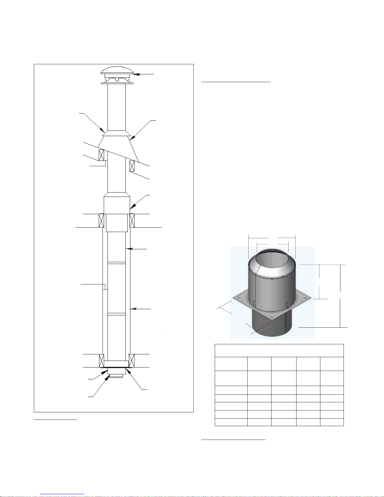
INSTALLATION PROCEDURES:
CEILING SUPPORT
To complete a proper Ceiling Support installation, the following
parts may be required.
- Ceiling Support: For joist supported chimney system.
- Attic Insulation Shield: Where a chimney enters an open attic
space.
- Firestop Joist Shield: Installed where the chimney passes from
one living space to another living space or as specified in the
listed factory-built fireplace installation instructions.
Authority require that the chimney extend not less than 3ft (900
mm ) above the highest point where it passes through the roof of
a building and not less than 2ft (600 mm) higher than any portion
ofa buildingwithin 10ft (3m) horizontally. See Figure 1 and Chart
2 in the back of these instructions.
FRAMING DETAILS:
Plan your installation carefully. If possible, position the appliance
so that the flue outlet is centered between joists, rafters or studs.
Drop a plumb line to the center of the flue outlet and mark this
center point on the ceiling. Lay out and frame all openings
ensuring the specified 2” clearance to combustibles is main-
tained. All openings should be square, plumb and in perfect
alignment with each other (see Figure 2). For angled roofs, en-
sure that the framing dimensions are measured on the horizon-
tal plane (see Figure 3).
FRAMING DIMENSIONS FOR MODEL UT
TO MAINTAIN 2 INCH AIR SPACE CLEARANCE
MODEL UT
Chimney Inside
Diameter:
All other framing*
CeilingSupport*
*All framing dimensions may be up to 1/2” more, but not less than the above values.
Table 1
The following instructions will assist you in the installation of your
chimneywitha CeilingSupport. Thissupportwill holdup to15.25m
(50’) of chimney sections, all of which must be installed above the
support.
1. Frame a level square opening (all four sides). Inside dimen-
sions should conform to Table 1.
2. With the Lower Bucket removed, place the upper bucket
assembly into the framed opening from below.
3. Ensure that the support plate is level and flush and drive one nail,
1-1/2” common or spiral, part way into each of the four (4) nailing
areas of the support. You may substitute nails with #8x1-1/2” wood
screws.
4. Finish nailing through all prepunched holes (12 nails total) and
fasten the finishing (support) plate to the ceiling (see Figure 4).
5. Replace the Bucket Section from above. Connect the proper
sized Stove Pipe Adapter to the first chimney length. Lower this
chimney section down into the bucket section, with the male end
pointing upwards as indicated by the arrow on the chimney label.
6. Additional chimney lengths above the support are simply
stacked on, twist locked with a 1/8 clockwise turn and secured
with a locking band at each chimney joint. A locking band is
supplied with every chimney length and must be used on all
chimney joints, interior or exterior. Stainless steel sheet metal
screws (maximum length of 12.70mm (1/2”) may be substituted
on interior joints.
7. Finish the chimney to its required height.
8. If an offset is installed in the system, an Offset Support must be
installed as shown in Figure 7.
9. If the chimney extends 5 feet (1.5 m ) or more above the roof,
additional lateral support is required, such as the Universal Roof
Brace Kit.
3 ft.
(900mm)
min.
2 ft.
(600mm)
10 ft.
(3m)
2ft.
(600mm)
3 ft. (900mm)
min.
FIGURE 1 - Roof Flashing: Required when the chimney penetrates a roof.
- 15° , 30° or 45° Elbow Kits (2 per box with locking bands and
elbow support).
- Suitable lengths of chimney: Available in 6”, 12”, 18”, 24” and
36” lengths. A 48” length is available in 6” and 8” only.
- Round Top
- Stove Pipe Adapter
Chimney Length
Lower Bucket
Upper Bucket
The Ceiling Support is intended for installation below a finished
or unfinished ceiling.
Figure 4
CathedralSupport
Support Plate
Stove Pipe Adapter
Figure 3
Typical Roof Joist
Framing
Figure 2
Typical Joist Framing
5” 6” 7” 8”
10 1/4”
12 1/4”
11”
11 1/4”
N/A
13”
12 1/4”
N/A
14”
10 1/4”
12 1/4”
12”
Page 5
280 x 280 305x 305 330x 330 356 x 356
A
B
C
D
“A” DIM.
“B” DIM.
“C” DIM.
“D” DIM.
“E” DIM.
E
FIGURE 5
CeilingSupport
- Together with a fully framed opening (all four sides) it controls
vertical and horizontal spread of any fire external to the chimney.
- It stabilizes the chimney in the framed opening and defines and
maintains the required two inch AIR SPACE clearance to combustibles.
- It prevents heat losses from the dwelling by blocking vertical air
circulation in the space around the chimney.
- It helps provide stability for chimney extending above the roof.
ATTIC INSULATION SHIELD
The function of the Attic Insulation Shield (or a complete enclo-
sure) is to keep insulation from coming into contact with the chim-
ney. Where height restrictions will not permit the use of the Attic
Insulation Shield, an enclosure from the attic joist to the roof joist
will be sufficient. All chimney enclosures must maintain the re-
quired minimum air space clearance of 50mm (2”) to the chim-
ney (see Figure 5).
For proper installation, the attic opening should be fully framed
at 2 inches clearance to the chimney pipe with framing material
of the same dimension as the ceiling joists as per Table 2. The
tabs on the base plate of the AIS are inserted in the framed
opening around the chimney. Nail the AIS base to the framing
dimensions with at least 2 nails per side using 2d (1”) spiral
nails or 1” x #8 wood screws.
The Attic Insulation Shield allows for a depth of insulation of 10
inches plus the depth of the ceiling joists. If insulation is blown
in and adheres to the chimney pipe, it should be brushed off to
eliminate any possible contact of this material with the chimney
surface.
FIRESTOP JOIST SHIELD
A Firestop Joist Shield must be installed where the chimney
passes from one living space to another living space. It is
installed from either above or below the joist. Nail the Firestop
Joist Shield using 1-1/2” common or spiral nails, into the framed
opening outlined in Table 1.
Bucket Section
Floor, CeilingJoist
(Framed all 4 sides)
LIVINGSPACE
*Follow Appliance instructions for proper clearance. If clearance is not given, use
460mm(18”) min.
*Stove Pipe Adapter
Framed
Enclosure
2” (50mm)
clearance from
chimney to
combustible wall
Chimney Lengths
50mm (2”) minimum air
space clearance to
combustible material
ATTICSPACE Attic Insulation
Shield
50mm (2”) minimum air
space cleance to
combustible material
Round Top
CeilingJoist
(Framed all 4 sides)
Stom Collar
FIRESTOPPING:
Firestopping is required at every joist level. Wherever a chimney
passes through a ceiling or floor, through a wall, or into an enclo-
sure, it must be firestopped. No firestopping is required in con-
junction with a Ceiling Support installed as shown in Figure 5,
the Ceiling Support provides the firestopping. Firestopping per-
forms the following essential functions for both the dwelling and
the chimney.
FIGURE 6
Roof Flashing
Warning: The chimney lengths and its fittings must be assembled
with metal-to-metal joints as furnished. Do not use tape or any
sealing compound (such as tar, mastic, putty or silicone) at the
outer joints. Sealers in the joints may cause the insulation to
accumulate moisture and may cause corrosion or freezing failures.
FRAMING DIMENSION CHART
FOR ATTIC INSULATION SHIELD
DIAMETER OF
CHIMNEY
FRAMED
OPENING
Table 2
5”
11 x 11
6”
12 x 12
7”
13 x 13
8”
14 x 14
7 -1/4”
11”
10“
13“
18 -1/2”
8 -1/4”
12”
10“
14“
18 -1/2”
9 -1/4”
13”
10“
15“
18 -1/2”
10 -1/4”
14”
10“
16“
18 -1/2”
Page 6
X X X X
X X X X
X X X
127mm 152mm 178mm 203mm
183
(7-3/16”) 210
(8-3/16”) 233
(9-3/16”) 259
(10-3/16”)
280 x 280
11” x 11” 305 x 305
12” x 12” 330 x 330
13” x 13” 356 x 356
14” x 14”
Table 3
Table 4
Chimney Size 5” 6” 7” 8”
Minimum Framed Opening for
Combustible Wall
Minimum Round Hole
Diam. For Non-Combustible Wall
The female end of the elbows are not lanced in order to ensure
proper alignment of the chimney system can be maintained.
Install and position the insulated elbow on the vertical chimney
length in the required direction. Fasten the elbow to the chimney
length with the supplied locking band.
Place the required offset chimney length(s) (see Offset Chart for
appropriate length(s)) on the elbow. Turn it clockwise to lock it in
place and install the supplied locking band.
Install the remaining offset elbow to return the chimney back to
the vertical position. Again secure in place with the supplied
locking band. *Locking bands and/or stainless steel sheet metal
screws can be utilised with a maximum length of 12.70mm (1/2”)
only on all chimney joints forming an offset.
During installation provide supplementary support for the offset
section to avoid undue stress on connected elbows.
Install an Elbow Support on the vertical length just above the
highest elbow. Securely clamp the support band to the chimney
length just above the locking band at the joint. Attach the support
straps to the support band assembly and nail them to the framing
using 1-1/2” nails or #8 x 1-1/2” wood screws (2 per straps) as
per Figure 7.
Never install an elbow in a joist area. Chimney sections must
pass vertically through framed joist areas.
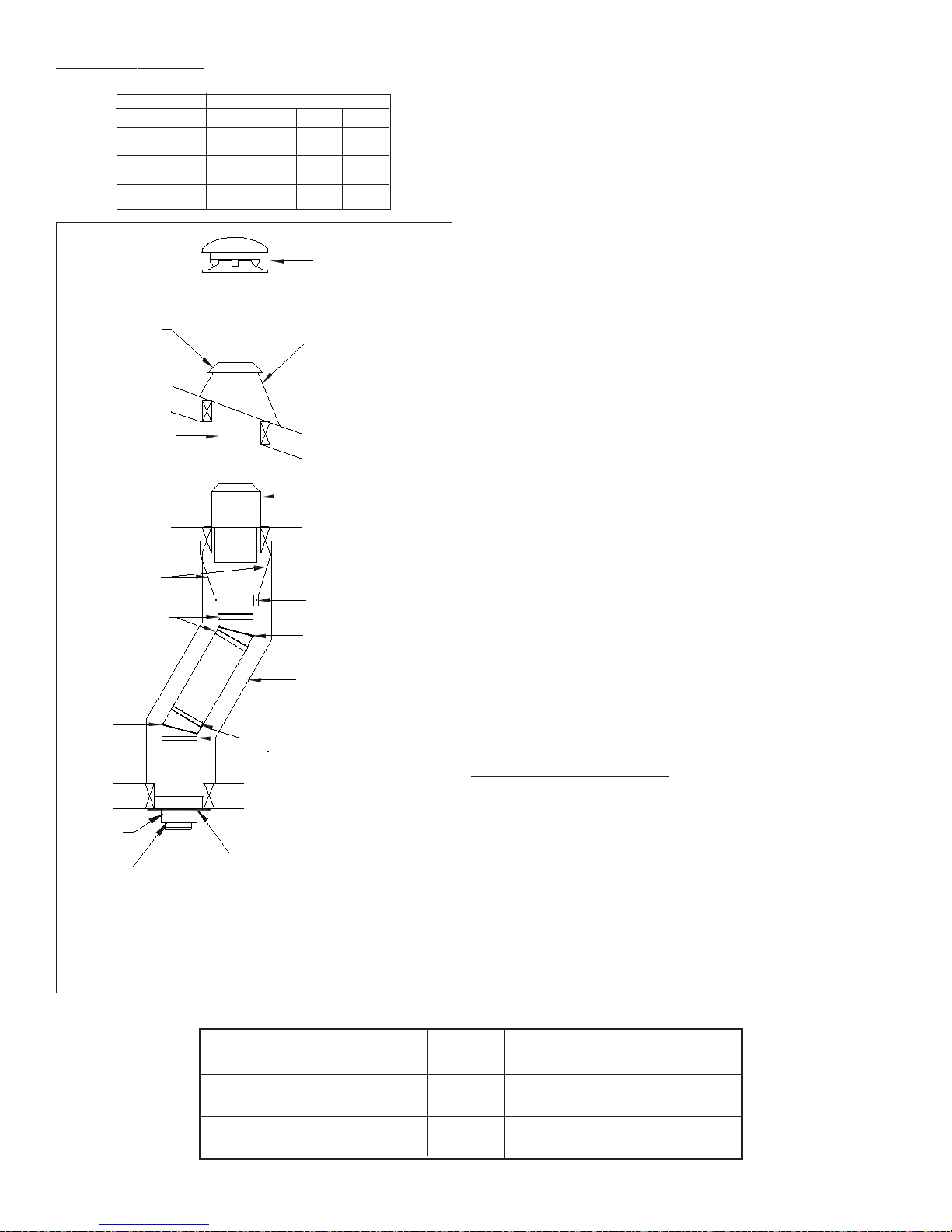
ELBOW INSTALLATION
Elbow Kits (2 elbows, 1 offset support and 4 locking bands).
FIGURE 7
Attic Insulation Shield
Storm Collar
Elbow Locking Bands
Intermediate/Elbow
Support Straps
Locking Bands Elbow
CeilingSupport
Roof Flashing
If the offset length is more than 1.2m (4’), an intermediate support
must be employed at 1.2m (4’) intervals. Maximum offset length
4.8 m (16’), the intermediate support must be used in conjunction
with an offset support.
Round Top
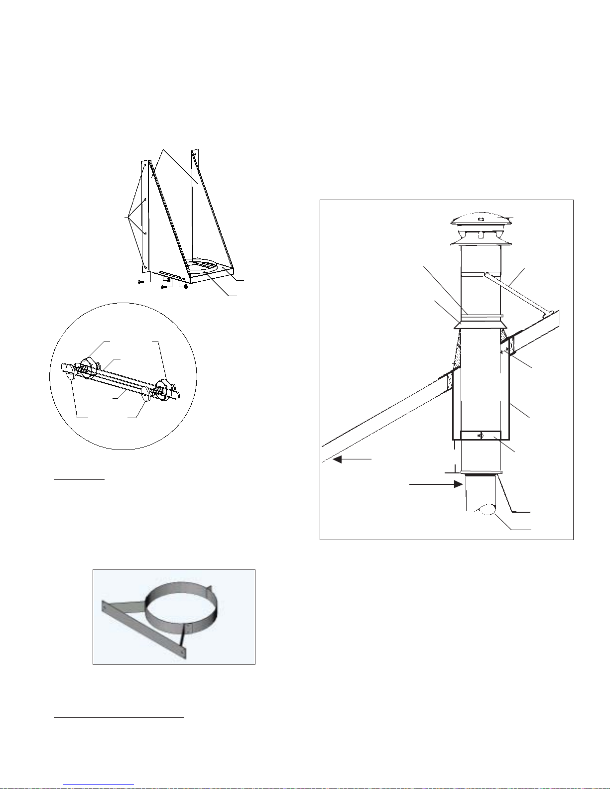
ADJUSTABLE W ALL SUPPOR T
As previously mentioned, the ideal location for your chimney
system is within the building envelope. An Adjustable Wall
Support is required when the above mentioned location is not
possible.
The adjustable Wall Support will allow for an adjustment of 2” to
6” from a vertical wall. Threaded studs are factory installed on
both side brackets and the support plate for fast and easy
assembly (see Figure 9).
One pair only of (two) 15 or 30 or 45 degree elbows may be used
to provide an offset in order to avoid cutting of joists and to clear
other obstructions. The vertical run of chimney above an offset
must be supported with an elbow support. Each elbow support
will support 10m (30’) of chimney. If the offset length is more than
1.2m (4’), an intermediate support (plumbing straps not supplied)
must be installed at 1.2m (4’) intervals in conjunction with an offset
support. Maximum offset length is 4.8m (16’). See Figure 7 and
the Offset Chart for assistance in selecting your offset.
15° Elbow Kit
30° Elbow Kit
45° Elbow Kit
MODEL UT
Framed Enclosure 2”
(50mm) clearance from
chimney to combustible
wall
Elbow Support Band
Roof Joist
(Framed all 4 sides)
Chimney Section
Lower
Bucket
Stove
Pipe
Adapter
Floor,Ceiling Joist
(Framed all 4 sides)
5” 6” 7” 8”
Page 7
2
2.5
3
3.5
4
4.5
5
5.5
6
74
73
71
69
66
62
58
52
45
63
62
60
59
56
53
50
45
39
56
55
53
51
49
46
43
38
34
49
48
47
46
44
42
39
35
30
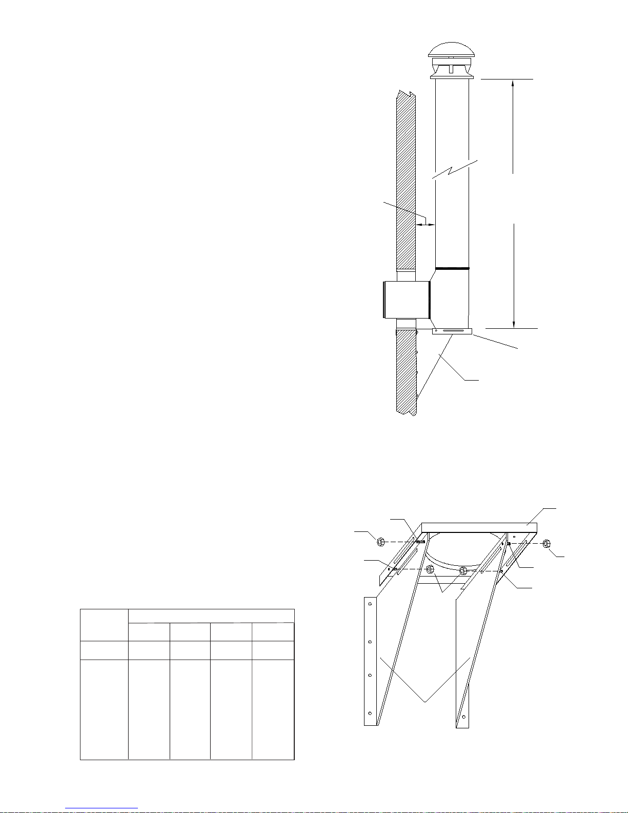
The following steps will assist you in the installation of the
Adjustable Wall Support. Figure 13 shows a typical Wall Support
installation.
To complete a proper Wall Support installation, the following
parts may be required:
-Adjustable Wall Support: Intended for a through-the-wall
installation where the chimney has a horizontal connection.
-Suitable Lengths of chimney: Installed above the support.
-Through-The-Wall Length: Attaches to tee branch.
-Insulated Tee w/Plug
-Insulated Wall Thimble:Required to pass through a combustible
wall.
-Wall Band: Required to provide lateral support to the chimney.
-Round Top: To prevent rain and/or debris from entering in the
chimney.
-Stove Pipe Adapter:To connect from the chimney to appliance’s
flue pipe.
-Roof Flashing: Required when the chimney penetrates a roof or
a roof overhang.
2. For a non-combustible wall (concrete block or poured
foundation), cut a hole 5mm (3/16”) greater in diameter than the
outside diameter of the chimney as per Table 4.
1. Determine the centre line of the horizontal connection (length
through the wall) and frame an opening to the dimensions
specified in Table 4.
3. After framing in your opening to the dimensions specified in
the Framing Dimensions in Table 1, install the outer half (with the
unfinished square plate) of the Insulated Wall Thimble in the
outsidewallopening. Secure inplaceusing appropriatefasteners
through the pre-punched holes.
4. Install the inner half (with black plate) of the Insulated wall
Thimble in the inside wall opening, ensuring that the shield slides
into the shield of the outer half. Once in place and flush against
the wall, fasten with appropriate fasteners through the pre-
punched holes.
Distancefrom
Wall to
Chimney 5” ID
Chimney 6” ID
Chimney 7” ID
Chimney 8” ID
Chimney
H(feet)
Max. Height H (feet)
Max. Height H(feet)
Max. Height H(feet)
Max. Height
D (inches)
Wall/Chimney
Table 5 - Wall Support Chimney Height Chart
The maximum chimney height above an Adjustable Wall Support
is indicated in Table 5 and illustrated in Figure 8, all of which
must be above the support.
FIG. 8 - See Table 1 for Maximum Chimney
Heights based upon Chimney Diameter and
Distance from Wall
“H”
Max.
Chimney
Height
“D”
Distance
from Wall to
Chimney
Support Bracket
Support Plate
5. Assemble the side Brackets (point of triangle facing down) to
the Support Plate (flange up) by inserting the threaded studs into
the oblong slots. Install the supplied nuts on the threaded studs.
(see Figure 9 & 10).
Support Side
Brackets
Support Plate
Threaded Stud
Support Bracket
Threaded Stud
Nut
Support
Plate
Nuts
Nut
Support Bracket
Threaded Stud
Support
Plate
Threaded
Stud
FIG. 9 - UNDERSIDE VIEW OF
THREADED STUDS AND NUTS
Never offset an exterior chimney.

Page 8
Insulated Wall Thimble
Telescoping adjustment
from 6” to 11”
Insulation
Blanket
Interior Inner
Half of
InsulatedWall
Thimble
Exterior Outer
Half of
InsulatedWall
Thimble
Figure 11
Insulated Wall
Thimble
Combustible Inside Wall
76mm (3”) min.
660mm (26”) max.
Insulated Chimney
Length
Min. Clearance to
Combustibles (50mm)
Fig. 13 - Wall Support
Installation
Lag Screws Into
Structure Bracket
Support Plate
Wall Support Kit
Locking Band
Insulated Tee
Full Enclosure
Recommended.
Both Indoors
and Outdoors
Use Locking
Bands on All
Joints
Wall Band Every
8 Feet
9. Place the insulated Tee on the support plate ensuring that the
male coupler of the Tee is facing up and the flange on the top of
the plate slides into the female coupler. Insert and secure theTee
Capwith theattachedretainer clips(see Figure12). In earthquake
zones, secure the Tee to the flange on the support plate by
installing 2 stainless steel sheet metal screws as per figure 12.
10. For extension of the Tee, slide an appropriate insulated
Chimney Length through the Wall Thimble and attach it to the
horizontal branch of the Insulated Tee with the supplied locking
band. Make sure the nut and bolt are facing down to prevent any
water from collecting in the locking band. The insulated length
must protrude at least 76mm (3”) through the wall into the room
as per Figure 13.
Stud and Nut
located to front
of Support
Bracket
Support
Brackets
Threaded Stud
and Nut
located at
rear of
Support Plate
Pre-
Punched
Holes of
Support
Bracket
Flange Up
Holes for Retainer Clips
FIG.10-FRONTVIEWOFWALLSUPPORTASSEMBLY
Support
Plate
6. Ensure that the Wall Support is level, and secure to the wall
through the pre-punched holes located on the sides of each of
the wall support brackets using (8) #14 x 1-1/2” hex head lag
screws or #10 x 1-1/2” wood screws. You can drill 5/32” pilot
holes for the lag screws.
7. Once in its final position and all clearances have been met,
tighten each of the nuts on the threaded studs.
8. Attach the two (2) retainer clips to the bottom of the support
plate and fasten with the supplied nuts and bolts using the two
(2) holes on top of the support plate (see Figures 10 & 12).
FIG. 12 - SECURINGOFTEE CAP
Support
Plate Retainer
Clip
Tee Cap
Earthquake zones
secure Tee to the
Support Plate
with stainless
steel screws
Insulated Tee
WARNING: Tee Cap and Retainers must be installed.
Failure to install retaining clips could cause fire,
injury or death.
Wing Nut
11. Use a non-hardening high-temperature sealant (500oF) to
seal around the horizontal length where it enters the wall thimble
or the concrete wall.
12. Chimney lengths above the InsulatedTee are simply stacked
on and locked with a 1/8 clockwise turn. Locking bands must be
used on all joints.
13. For lateral stability of the chimney above the support, a Wall
Band must be used every 8 feet, and at least one Wall Band
must be installed. Interior chimneys must use the Firestop Joist
Shield (JS) in place of Wall Bands if extending through floor /
ceiling penetrations.
Page 9
76mm
(3”) min.
-Suitable lengths of chimney
-Stove Pipe Adapter
-Trim Collar
-Round Top
Flashing Minimum
50mm 2”
air space
clearance
Universal
Roof
Brace Kit
Storm Collar
Locking
Band
Stove
Pipe
Adapter
Follow
Appliance
Instructions
for proper
connector
clearance
Support
Band
Cathedral
Ceiling
Support
FluePipe
Round Top
Figure 17
NOTE: The male coupler of the chimney length must be pointing
upwards as per the arrow on the chimney label.
The bottom chimney length should protrude into the living space so
that proper clearances are maintained at the adapter (see Figure 17).
The Cathedral Ceiling Support Box is manufactured to an over-
all outer dimension of 12” x 12” (305mm x 305mm). Therefore,
thesuggestedframingtofittheboxis12-1/4”x12-1/4”(311x311mm).
suspend the chimney below the roof. To complete a proper
Cathedral Ceiling Support installation, the folllowing parts may
be required:
-Cathedral Ceiling Support /w 4 painted ceiling trim angles
-Roof Flashing w/ Storm Collar
The following instructions will assist you in the installation of
your chimney with a Cathedral Ceiling Support. This support will
hold up to 30’ of chimney, of which 15’ can be suspended below
thebox. Chimneyjoints madebelowthe supportmustbe secured
with locking bands.
Wall Band
WALL BAND
The Wall Band is used along an outside wall at 8 ft intervals for
lateral stability. Secure the Wall Band bracket to the wall using
two 6d or 2” spiral nails. For concrete walls use suitable masonry
fasteners.The nut and bolt supplied will fasten the band around
the chimney.
Figure 16 After framing in your opening to the dimensions specified above
and in Table 1, slide the Cathedral Support Box into the joist/
rafter opening. Once the box is at the desired location, ensure
the box is level and plumb. Nail the box to the framing using four
2” spiral nails or equivalent per side. The excess material stick-
ing above the roof can either be trimmed off before attaching the
box to the framing or, after it is installed the corners can be cut
and the excess material folded down onto the roof deck.
Install the Support Band on a chimney length at the desired
CATHEDRAL CEILING SUPPORT
A Cathedral Ceiling Support is available for 5” and 6” diameters
chimney only. For other diameters, a roof support can be used to
NOTE: Invertingthebrackets(bracketsmounted abovethesupport
plate) can be accomplished by inserting extra bolts through the
oblong slots of the support side brackets and the support plate
as per Figures 14 and 15. Secure with nuts. In this position, the
range of adjustability is limited to 5” from the wall.
Nuts
Slot on
Support
Bracket
Support Brackets
Pre-Punched
Holes of Support
Bracket
Support Plate
w/ Flange Up
Front Hole for
Retainer Clip
Slot on
Support
Plate
Bolts
FIG. 15- SLOTAREAS
WITH BOLTSAND NUTS
ASSEMBLYOFSUPPORT
BRACKET AND
SUPPORTPLATE
FIG. 14-FRONTVIEW OF
WALLSUPPORT
ASSEMBLYWITH
BRACKETSMOUNTED
ABOVETHESUPPORT
PLATE
Page 10
158
7
6
4
32 910
1
26
453 78910
11
11
3”
ROOF SUPPORT
5. Using the bent chimney plate as a template, drill 3/32" holes in
the outer casing of the chimney (do not penetrate more than 12
mm (1/2'’) into the chimney). Attach the plate with the small
sheet metal screws provided.
6. Install the second plate in a similar manner on the opposite
side of the chimney length.
The following instructions will assist you in the installation of
your chimney with a Roof Support. This support will hold up to
9.0 m (30') of chimney of which 6.0 m (20') may be suspended
beneath it.
Figure 18
Figure 19
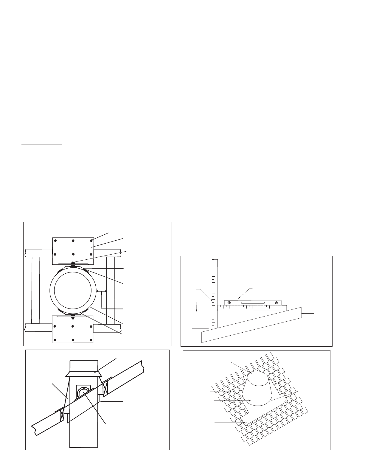
ROOF FLASHING:
Ensure that you have the proper roof flashing by checking your
roof pitch using a level and two rulers (see Figure 20) or by
using a roof pitch card.
12” Ruler Level
Roof Pitch is 3/12
Figure 21
Figure 20
Flashing
Storm Collar
Roof Support
50mm (2”) min.
clearance
Insulated Chimney
Length
Shingles
Nails
Flashing
Framed Opening
Chimney Plate
Carriage Bolt
50mm (2”) min.
clearance
Chimney length
Bend to fit curve of
chimney
Roof Bracket
Large wood screws provided
Small sheet metal
screws (provided)
1. Frame a rectangular roof opening to provide a 50mm (2") mini-
mum clearance from combustible materials (See Figure 18).
2. Bend both chimney plates at the vertical slots to fit the outside
curvature of the chimney length (Figure 18).
7. Attach the Roof Brackets to the chimney plates. Centre the
assembly in the roof opening, ensuring that a 2” clearance to
combustible is maintained.
8. Adjust Roof Brackets to the roof pitch and tighten nuts. Attach
to the roof with six (6) large wood screws per bracket
with the inner-most screws going into the rafters or headers
(See Figure 18 & 19).
9. Additional chimney lengths above the support are simply
stacked on and locked with a 1/8 clockwise turn.
10. Locking Bands must be used on all exterior joints.
11. Finish the chimney to its required height. If the chimney
extends 1.5 m (5') or more above the roof, a Universal Roof
Brace Kit is required (see Figure 22).
3. Determine the chimney plate position on the chimney casing
(See Figure 19).
4. Install two (2) carriage bolts per chimney plate in the square
holes.
position by tightening the support band with the bolt and nut.
Secure the band to the chimney outer casing by screwing four
stainless steel sheet metal screws through the support band
andinto theoutercasing. Lower thechimney lengthdownthrough
the opening in the bottom of the support box, so that the Support
Band makes contact with the bottom of the Support Box (see
Figure 17).
Install additional chimney sections and lock together by turning
clockwise until the two sections lock together tightly. Locking
bands must be used at all joints. Continue in this manner until
the required height above the roof is achieved.
Chimney sections installed below the Cathedral Support are
locked together from below by turning counter-clockwise until
tightly locked together with each joint being secured by locking
bands which are provided. Do not offset the chimney below the
Cathedral Support.
Roof
Apply a bead of
silicone caulking
along the seam
where the plate
meets the cone.
Apply a bead of
silicone caulking
along the back
seam of the
cone

Page 11
4
4
5
5
18
21
23
27
UNIVERSAL ROOF BRACE KIT
If the chimney extends 5 feet (1.5m) or more above the roof deck,
a Universal Roof Brace Kit is required. The Universal Roof Brace
Kitcontains2 telescopic legs,brackets, band strap andhardware
package. The band strap is wrapped around the chimney and
the two telescopic legs bolted to the roof brackets.
The Flashing and Storm Collar may be painted to match the roof
shingles. This will extend its life and improve the appearance. The
chimney may be painted also with a HEAT RESISTANT paint. To
improve adhesion to the chimney, degrease, clean and prime
before painting. Follow the paint manufacturer’s instructions.
Continue adding chimney lengths until the proper height is
achieved (see Figure 1 and Chart 2). Install a Round Top. The
Round Top prevents entry of moisture which might lead to prema-
ture deterioration of the chimney.
On metal or steep roofs, it is recommended that an ice deflector
or “cricket” fabricated from heavy-guage galvanized steel be
installed. The wedge-shaped deflector is installed 2” from the
chimney on the upper slope. Its function is to split ice and snow
as they slide down the roof, preventing damage to the chimney.
This is not a supplied item. Contact your dealer or a sheet
metal fabrication shop in your area for your custom ice deflector.
This also should be painted with a suitable metal paint by
following the paint manufacturer’s instructions.
Once you have marked and located the area where the chimney
will come through the roof, center, position and prepare the roof
area by removing shingles, shingle nails and cutting the roofing
material. Frame a RECTANGULAR opening to suit the pitch of
the roof and ensure that a 2” (50mm) clearance is maintained to
combustibles on all four (4) sides. This is done before extending
the chimney above the roof. Do not nail the flashing to the roof at
this time as ajustments may be required.
Slide the top edge (nearest the roof peak) of the flashing under
the roofing shingles. At least half of the flashing (top and sides)
should be UNDER the shingles and the lower end OVER the
shingles to provide a watershed. Trimming off the shingles may
be neccessary around the cone of the flashing for a better fit. On
existing roof application, lower a chimney length into the flashing
opening and twist lock in place and secure with a Locking Band.
Ensure that the chimney is level and plumb before nailing the
flashing to the roof.
Nail the flashing to the roof deck (also under the shingles) along
the upper edge and down each sides with 12 nails with neoprene
washers or cover the heads with a suitable non hardening
waterproof caulking. Seal the shingles to the plate in the same
manner. As a precaution, apply a bead of caulking along all
seams of the flashing as per Figure 21.
Apply a non-hardening high temperature silicone caulking just
above the top of the flashing cone where it meets the chimney
casing. Slide the Storm Collar through the applied caulking and
place into its final position to ensure a waterproof joint. Apply
additional caulking above the Storm Collar as required.
Two (2) pockets must be formed to attach the telescopic legs
(use Figure 23 and the Selection Chart below as guide).
Tab “A” is formed at one end by bending the strapping band
(clearing the first hole). The number of holes counted away from
Tab “A” (including the first hole) will identify the location of the
first pocket. Attach at this location the “U” bracket by inserting a
bolt through and securing with the supplied nut.
To formTab “B”count the holes away from the“U”bracket. At this
location a bolt is inserted into the holes creating the other pocket.
Fasten the larger diameter section of the telescopic leg to the
“U” bracket using the bolt and nut.
FIGURE 22
Eye Bolt
Clamp
Storm Collar
Flashing
Locking Band
Nut & Bolt
RoundTop
BandStrap
TelescopicLeg
Nails
FIGURE 23
UT/ST
Inside Diameter # Holes from "Tab A" for
the "U" Bracket # holes from "U" Bracket
to bolt hole in tab "B"
Hole/Tab Selection Chart
"U" Bracket
(1st Pocket)
Tab "A"
Tab "B"
Bend the strapping of
Tab "A" and "B" to form
2nd pocket and cut off
excess material
5”
6”
7”
8”
Page 12
B
C
A
4. Always secure all single wall flue pipe joints with a minimum
of 3 screws.
5. Obtain proper attachment parts for the appliance end and for
the entry to the chimney.
6. Locate or support the flue pipe to avoid contact of damage.
7. Caps or plugs for single wall tees should be secured
against falling out and designed so they can’t leak creosote
or rain.
The band is clamped around the chimney and the two legs
bolted to the roof. Position the band approximately two thirds of
the way up the chimney height. The preferred location for the
band is next to a joint, immediately above or below a locking
band and fasten the other telescopic leg to Tab “A” and Tab “B”
using the bolt and nut provided.
Secure the bottom end of each telescopic legs to the roof brack-
ets and the roof brackets to the roof with supplied hardware as
shown in Figure 24. The two legs of the brace assembly should
form an angle of about 60 degrees to give support to the chimney
in all directions. Keep bottom ends equal distance from the
chimney and at approx. at the same elevation, on the high side of
the sloped roof. Ensure that the lags are anchored in rafters and
not just the roof deck. Seal the roof with a suitable non-hardening
waterproof sealant. After the legs are attached securely to the
roof brackets and to the band, tighten the eye bolt which locks
the two tubes together fixing the position of the telescopic legs.
Figure 24
SPARK ARRESTER
Use a spark arrester if you have a shingle roof or live in a for-
ested area. If the chimney is used for venting a gas appliance,
use a spark arrester to keep birds out.
The Spark Arrester is made of flexible expanded metal mesh.
Each size is cut to fit the appropriate size Round Top.
Wearing safety gloves, fit the bolt with one nut and place the
mesh between the dome and the skirt of the round top. It should
be midway between the inner wind band and the outer edges.
Do not place the screen directly against the wind band.
Once the Screen is wrapped around the band, secure it in place
with the 2nd bolt and nut.
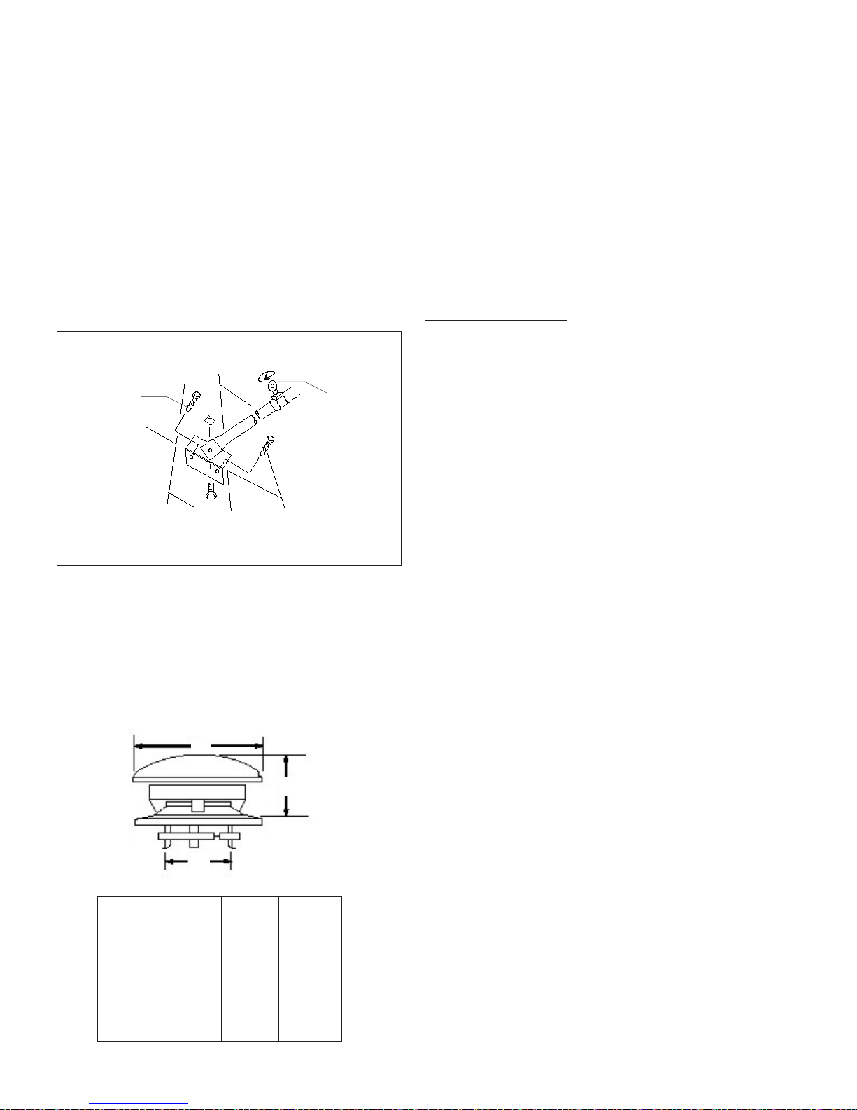
TYPE HT ROUND TOP
Attach the Type HT Round Top to the chimney by sliding it over
the chimney length. ensure that the three (3) vertical tabs are
located on the outside of the chimney length and that the
Round Top sits flush on the top surface of the length. Wrap the
band snug to the bottom of the 3 tabs and secure in place with
the supplied nut and bolt.
The connection of a single wall base tee or single wall flue pipe
or double wall flue pipe to the insulated chimney must be secured
with the screws supplied in the Support carton. The use of a
stove pipe adapter is recommended with the first length, this will
provide a positive connection between the insulated chimney
and the appliance connector. The Stove Pipe Adapter is inserted
into the female end of the first insulated chimney length and
extends beyond the ceiling support approximately 32mm (1-1/
4”). For a Cathedral Support and Wall Support application, the
stove pipe adapter is inserted into the female end of the exposed
chimney length and extend into the room and held in place with
the finishing collar secured with 4 screws which is used to
attach the stove pipe adapter to the finishing collar.
Install inter-connecting flue pipe following the appliance
manufacturer’s instructions, and appropriate building code
requirements keeping in mind that the flue pipe run should be
as short and straight as possible. All joints should be secured
in place with three (3) sheet metal screws.
Besides following the appliance instructions for flue pipe, other
rules that should be taken into account:
To comply with the National Building Code of Canada the single
wall base tee can be installed with a 229mm (9”) minimum air-
space clearance between connnecting single wall material and
combustibleproductsprovided thattheflue gastemperaturedoes
not exceed 400° C (750° F) (most oil fired appliances). Other-
wise, the minimum air space clearance must be 450mm (18”).
Refertothe applianceinstallationinstructions for theproper chim-
ney requirements.
STOVE PIPE ADAPTER:
Connect only to low heat (liquid fuel or gas fired) appliances
with continuous flue gas temperatures below 540° C (1000° F).
When installing a factory-built fireplace refer to the fireplace in-
stallation instructions for the proper chimney requirements.
1. Never enclose single wall flue pipe, even at 18 inches clear-
ance.
2. Never run it through ceilings or floors, or windows.
3. Don’t use single wall flue pipe outdoors.
Ensure that
the lags are
anchored in
rafters rather
than the
sheathing
Tighten the
eye bolt which
locks the
two tubes
together fixing
the position of
the telescopic
legs
Roof Bracket Secured to Roof
Chimney
Dia.
5”
6”
7”
8”
FIGURE 25
A
7”
8”
9”
10”
B
10”
12”
14”
16”
C
5”
5-1/2”
6-1/4”
7”

Page 13
With a new chimney installation, the chimney should be inspected
at least once every 2 weeks during the heating season to deter-
mine if a creosote or soot buildup has occured. When familiar with
the appliance and chimney characteristics, the chimney should be
inspected at least once every 2 months during the heating season.
If creosote or soot has accumulated, it should be removed to
reducethe riskofachimneyfire. Depending onthe rateof buildup,
as you learn what is going on in the chimney, you can adjust your
cleaning schedule.
If you have any doubts about your ability to clean the
chimney, or if the deposits are very heavy and hard to remove, call
a certified chimney sweep. Do not try to burn them off.
If chemical cleaner is used to assist in cleaning your chimney,
make sure it is a product which is non corrosive to the chimney
liner. The optimal method for cleaning a chimney is by a
mechanical brushing of the chimney in conjunction with a
complete evaluation of the system by a certified chimney sweep.
The National Fire Code of Canada states: “Every chimney flue
and flue pipe shall be inspected and cleaned annually or as
often as maybe necessary, to keep the chimney and flue pipe
free from dangerous accumulations of combustible deposits”.
CHIMNEY FIRES AND WHAT TO DO ABOUT THEM:
Your Selkirk chimney is not intended or designed for use as a
combustion or fire chamber. If the fire in your appliance has
gotten out of control, or if you suspect a chimney fire for any
reason, follow these steps:
1. Immediately close all dampers and/or air entrance to your
appliance.
2. Alert your family to the possible danger.
3. Inspect your appliance and chimney for possible fires, if in
doubt, alert your Fire Department.
4. Do not use salt or water on the fire. Salt is corrosive and water
will cause a dangerous steam explosion. You may be able to
control the fire by using ashes, sand or baking soda, since baking
soda is an ingredient used for dry chemical fire extinguishers.
5. Donotcontinue to useyourappliance until itandyour chimney
have been thoroughly inspected by a certified service technician.
6. After a chimney fire, when it is safe to do so, check internal
locations such as the attic and under the roof and keep watching
for two or three hours. There may be delayed smoldering and
subsequent ignition even if the fire inside the chimney has been
controlled.
The Anchor Plate can be used for adapting the UT chimney to a
“Listed” Factory-Built Fireplace certified for use with Model UT.
Follow the installation instructions accompanying the fireplace.
NOTE: Itis ofutmostimportance thatthe AnchorPlatebe installed
in accordance with the manufacturers installation instructions
accompanying the “listed” Factory-Built Fireplace.
MODEL UT ANCHOR PLATE
CHIMNEY OPERATION AND MAINTENANCE:
The need for chimney maintenance depends on the kind of ap-
pliance and how it is operated. Gas and oil-burning appliances
need very little, but wood-burning appliances may need a great
deal of chimney maintenance.
IMPORTANT
Burning wood produces creosote, soot, and fly ash which tend to
collect in chimney flue and on termination parts causing reduced
flow of gases through the chimney. Check top weekly for exces-
siveaccumulationof thesenormal combustionproductsand clean
as necessary. If the spark arrester becomes clogged with creo-
sote, it should be cleaned or replaced.
®
www.selkirkcorp.com
Selkirk Canada Corporation
P.O. Box 526, Depot 1
Hamilton, ON L8L 7X6
Toll Free: 1.888.SELKIRK (735.5475)
Selkirk Corporation
5030 Corporate Exchange Blvd.
Grand Rapids, MI 49512
Toll Free: 1.800.433.6341
Page 14
AABBAB
AB
13-3/4"
18-7/8"
22-3/4"
28"
N/A
37-1/2"
44"
53-1/2"
58-7/8"
68-3/8"
N/A
3-5/8"
6-1/8"
8-1/2"
11-5/8"
N/A
16-5/8"
20-7/8"
25-1/2"
28-3/8"
33-1/4"
N/A
3"
5-1/4"
8-1/8"
11-1/8"
13-3/4"
16-1/8"
20-1/4"
24-7/8"
28-3/8"
32-5/8"
26"
13-1/4"
17-5/8"
22-7/8"
27-7/8"
33-1/4"
37-1/2"
43-3/4"
53-3/8
58-3/8"
68-1/2"
54"
AABBAB
N/A
N/A
N/A
N/A
N/A
N/A
N/A
N/A
N/A
N/A
N/A
AB
N/A
N/A
N/A
N/A
N/A
N/A
N/A
N/A
N/A
N/A
N/A
4-3/8"
7-3/4"
11-7/8"
16"
20-1/2"
23-7/8"
28-1/2"
36-1/4"
40-1/8"
47-7/8"
41-1/2"
12"
15-5/8"
19-3/4"
23-7/8"
27-3/4
31-3/8"
36-7/8"
44-3/8"
49-1/4"
56-1/2"
45-5/8"
AA
BBAB
AB
5/8"
1-3/4"
2-3/4"
4-1/8"
N/A
6-3/8"
8-3/8"
11-1/4"
13"
16-1/8"
N/A
7-1/2"
13-3/8"
17-7/8"
23-7/8"
N/A
34-1/8"
41-5/8"
52"
57-3/4"
68"
N/A
5/8"
1-5/8"
2-7/8"
4-3/8"
5-3/8"
6-3/8"
8-1/8"
10-5/8"
12-1/8"
14-3/8"
10-3/4"
7-1/2"
12-1/2"
18-1/8"
24"
29-3/4"
34-1/8"
41-1/4"
52"
57-5/8"
68"
53-1/4"
5/8"
1-7/8"
3"
4-1/8"
5"
6"
7-1/2"
9-7/8"
11"
13-3/8"
10"
8"
13-5/8"
18-1/2"
24-3/8"
30-1/2"
34-7/8"
42"
52-1/2"
58-1/2"
68-3/4"
53-1/2"
3-1/8"
2"
3"
4"
5-1/4"
6-1/4"
8"
10-1/8"
11-7/8"
15-1/8"
10-1/8"
8-1/8"
14-1/4"
18-3/4"
24-5/8"
30-3/8"
35"
42"
52-5/8"
58-1/2"
68-3/4"
54-3/8"
4-1/8"
7-1/8"
9-5/8"
12-1/2"
15-3/4"
18"
21-5/8"
27-1/2"
30-1/2"
35-3/4"
27-1/2"
15-1/4"
20-1/8"
24-1/4"
29-3/8"
34-7/8"
39"
45-1/4"
54-1/8
59-1/8"
68-1/2"
55-3/8"
4-1/4"
7-1/8"
9-1/2"
12-1/2"
15-1/2"
18-1/4"
21-7/8"
27-1/8"
30-1/2"
36-1/8"
28-1/2"
16-1/8"
21-3/4"
25-3/8"
30-5/8"
35-7/8"
39-1/2"
46"
55-3/8
60-1/2"
69-5/8"
56-5/8"
5-1/2"
9-3/4"
13"
17-1/4"
21-3/4"
25-5/8"
30-5/8"
38-1/8"
42-3/4"
50-1/2"
38-1/4"
14"
18"
21-3/4"
25-3/8"
29-7/8”
32-3/4"
38-1/8"
45-1/8"
49-1/4"
57-3/8"
46-1/2"
5-3/4"
9-1/2"
13"
17"
21-5/8"
24-5/8"
29-5/8"
38-1/8"
41-7/8"
49"
38-1/2"
15-1/8"
19-1/4"
22-1/2"
27"
31”
34-1/2"
39-7/8"
47"
51-1/2"
59-3/8"
48-7/8"
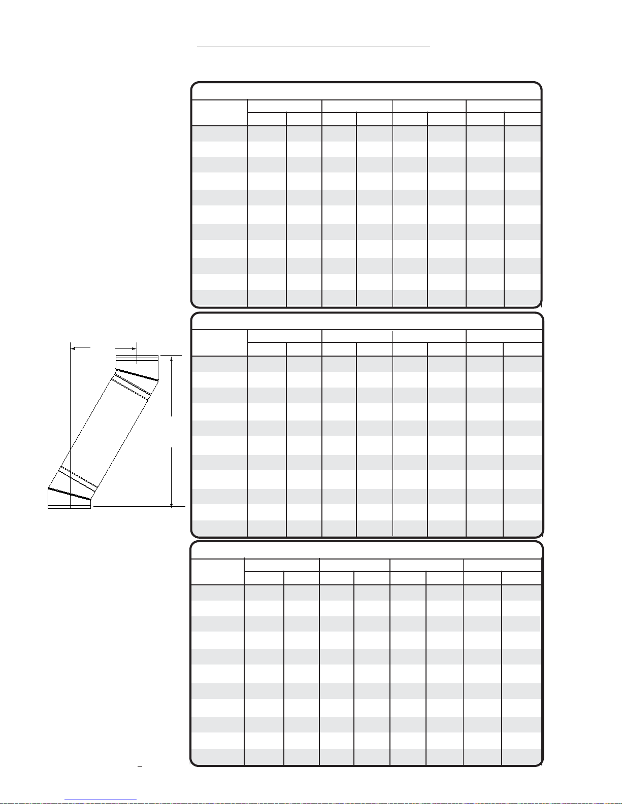
45o OFFSET CHART
Chimney
Lengths 7"Diameter
6"Diameter 8"Diameter
5"Diameter
30o OFFSET CHART
Chimney
Lengths 7"Diameter
6"Diameter 8"Diameter
5"Diameter
none
6"
12"
18"
24"
12" + 18"
36"
12" + 36"
18" + 36"
12”+18"+36"
48"
OFFSETCHART CHIMNEYINSTALLATION
It may be necessary to offset the chimney in order to clear a joist or an obstacle. The three (3) charts below will assist you in selecting
the proper combination of elbow angle and chimney length(s) that will provide the necessary degree of offset within an available height.
1. Select the column with the proper
chimney diameter of your system.
2. Determine the distance of the off-
setrequired by droppingaplumb line
for an accurate measurement. The
offset is measured at the chimney
centre line as per the "A" Offset
measurement in the diagram below.
3. On the chart, find the predeter-
mined distance (under the "A" col-
umn) required for the 15oelbow. For
greater offset, use the 30oor 45o
offset charts.
4. After finding the offset, look at the
“B”(height)measurement in the chart
to find the specified height. The
appropiate "chimney lengths" re-
quired in between elbows is found in
the left hand side column on the
chart.
NOTE:
• UltraTemp chimney can be
offsettedusing 15o, 30oor45oelbows.
Combining offsets for a greater angle is
not permitted.
• One pair of (two) 15o, 30oor
45oelbows may be used per interior
installation.
• Neverinstallan elbow in ajoist
area. Chimney sections must pass
vertically through framed joist areas.
• Each elbow support will sup-
port 30 feet of chimney.
•An intermediate support must
beusedat4feet intervals in conjunction
with an elbow support.
•The maximum length of
chimney allowed between elbows is
16 feet.
All measurements in inches.
Construction tolerances + one inch.
Offset
“A”
"B"
Height
none
6"
12"
18"
24"
12" + 18"
36"
12" + 36"
18" + 36"
12"+18”+36"
48"
15o OFFSET CHART
Chimney
Lengths 7"Diameter
6"Diameter 8"Diameter
none
6"
12"
18"
24"
12" + 18"
36"
12" + 36"
18" + 36"
12"+18" 36"
48"
5"Diameter

Page 15
44
42
40
38
36
*36
*36
*36
*36
*36
54
51
48
45
42
39
36
*36
*36
*36
64
60
56
52
48
44
40
36
*36
*36
74
69
64
59
54
49
44
39
*36
*36
84
78
72
66
60
54
48
42
36
*36
94
87
80
73
66
59
52
45
38
*36
104
96
88
80
72
64
56
48
40
*36
114
105
96
87
78
69
60
51
42
*36
124
114
104
94
84
74
64
54
44
*36
134
123
112
101
90
79
68
57
46
*36
144
132
120
108
96
84
72
60
48
36
*36
*36
*36
*36
*36
*36
*36
*36
*36
*36
1/12 2/12 3/12 4/12 5/12 6/12 7/12 8/12 9/12 10/12 11/12 12/12
*UT-36
*UT-24
*UT-18
*UT-12
*UT-06
*T-ITP
*T-EL15KIT
*TEL30KIT
*T-CSB
*T-AWS
*T-CCSK
URSP
*T-LB
*T-AD
DESCRIPTION
DESCRIPTION
*T-IWT
*T-WB
URBK
*T-AP
*T-AIS
*T-JS
*T-FS
*T-RT
*T-FF
*T-FA
*T-FAA
*T-SC
Requirement # 1 :
The code requires that the chimney must extend at least 3 feet (900mm) above the highest point of the roof that
it penetrates.
Requirement # 2 :
It must also be 2 feet (609mm) above any roof, wall or other obstruction within a horizontal distance of 10 feet (3m).
The following Chart is to assist you in determining the minimum chimney height you will require above the roof. You may need
to add to this height as nearby buildings, trees and other parts of the house roof could interfere with airflow over and around
the top of the chimney and affect its performance. If you think a nearby obstacle could affect draft, you might want to install
one or more additional lengths.
CHART 2 - CHIMNEY HEIGHT ABOVE THE ROOF
DISTANCE
FROM PEAK
10 Ft
9 Ft
8 Ft
7 Ft
6 Ft
5 Ft
4 Ft
3 Ft
2 Ft
1 Ft
CHIMNEY HEIGHT ABOVE ROOF (INCHES)
PITCH OF ROOF
* Defaulted to 36" to meet requirement #1. Both requirements (#1 and #2) must be met.
• If the chimney extends more than 5 feet or more above the roof, a Universal Roof Brace Kit is required.
•All lengths above the roof must havelocking bandsatalljoints. Thiswill eliminate the risk of sections becoming undonebelowtheroofline when
the Round Top is removed when inspections and cleaning of the system is being done.
All measurements are in inches with the exception of "distance from the peak" being in feet.
REPLACEMENT PARTS LIST
ULTRATEMP
PARTNO. ULTRATEMP
PARTNO.
36" Chimney Length
24" Chimney Length
18" Chimney Length
12" Chimney Length
6" Chimney Length
Tee with Insulated Plug
15o Elbow Kit
30o Elbow Kit
Ceiling Support
Adjustable Wall Support
Cathedral Ceiling Support Kit
Roof Support
LockingBand
Stove Pipe Adapter
InsulatedWallThimble
WallBand
Universal Roof Brace Kit
Anchor Plate
Attic Insulation Shield
Firestop Joist Shield
Firestop Spacer
Type HT Round Top
Flat Roof Flashing
1/12 - 7/12 Roof Flashing
8/12 - 12/12 Roof Flashing
StormCollar
* Specify chimney diameter (5, 6, 7 & 8 inches)

Page 17
Keep in a safe place for future reference
CHIMNEYMODEL:_____________________________
TYPEOFAPPLIANCE:__________________________
INSTALLATIONDATE:__________________________
DESCRIPTIONOFINSTALLATION(ChimneyandPipeConnectorConfiguration)_________________________________
___________________________________________________________________________________________________
___________________________________________________________________________________________________
PURCHASED FROM:
DEALERNAME:________________________________________________
Address:______________________________________________________
City:_________________________________________________________
Province:______________________________________________________
INSTALLED BY:
TECHNICIANNAME:____________________________________________
Address:______________________________________________________
City:_________________________________________________________
Province:______________________________________________________
INSTALLATION INFORMATION
Please register your Chimney with the Manufacturer.
Mail to: Selkirk Canada Corporation,
Product Registration, P.O. Box 256, Depot 1, Hamilton, ON L8L 7X6
Register Online @: www.selkirkcanada.com
Name: ________________________________________________________________________________
Address:______________________________________________________________________________
City:__________________________________________________________________________________
Province:_______________________________________ Postal Code:__________________________
Chimney Model:__________________________________ Installation Date:______________________
Technician Name:__________________________________ Address:____________________________
PRODUCT REGISTRATION
Table of contents
Other Selkirk Ventilation Hood manuals


Popular Ventilation Hood manuals by other brands


Electrolux
Electrolux Westinghouse WRF610WA Installation and operation manual

Windster
Windster RA-76 Series Operation manual

GE
GE JV960SCBR Specification sheet

Gorenje
Gorenje S1 WHC943A1XGB manual

GE
GE Cafe CV966TSS Dimensions and installation information

Logik
Logik L60CHDB17 Instruction & installation manual


