Selkirk CF Sentinel User manual

1
SELKIRK CANADA CORPORATION
950 South Service Road, Second Floor
Stoney Creek, ON L8E 6A2
1-888-SELKIRK (735-5475)
Fax: 1-866-835-9624
www.selkirkcorp.ca
2021 CF Sentinel 3009214 02/12/21
(6” to 8” dia.)
FACTORY-BUILT
INSULATED CHIMNEY
Installer: It is of the utmost importance that these instructions are
left with the homeowner.
Homeowner: Keep these instructions and maintenance guide in a safe
place for future reference.
INSTALLATION I NSTRUCTIONS
&
MAINTENANCE G UIDE
Tested to Standard
CAN/ULC-S629
&
UL 103 Type HT
PLEASE READ ALL INSTRUCTIONS
BEFORE BEGINNING YOUR
INSTALLATION.
FAILURE TO INSTALL THIS SYSTEM IN
ACCORDANCE WITH THESE
INSTRUCTIONS WILL VOID THE
CONDITIONS OF CERTIFICATION AND
THE MANUFACTURER'S WARRANTY.
A MAJOR CAUSE OF
CHIMNEY RELATED FIRES IS
FAILURE TO MAINTAIN
REQUIRED CLEARANCES
(AIR SPACES) TO COMBUSTI-
BLE MATERIALS.
IT IS OF THE UTMOST
IMPORTANCE THAT THIS
CHIMNEY SYSTEM BE
INSTALLED ONLY IN
ACCORDANCE WITH THESE
INSTRUCTIONS.
Model CF
LISTED

2
3
4
4
5
5
6
6
6, 7
7, 8
8, 9
9
10, 11
11
12
12, 13
13, 14
15, 16
16
16
17, 18
18
19
20
21
21
22
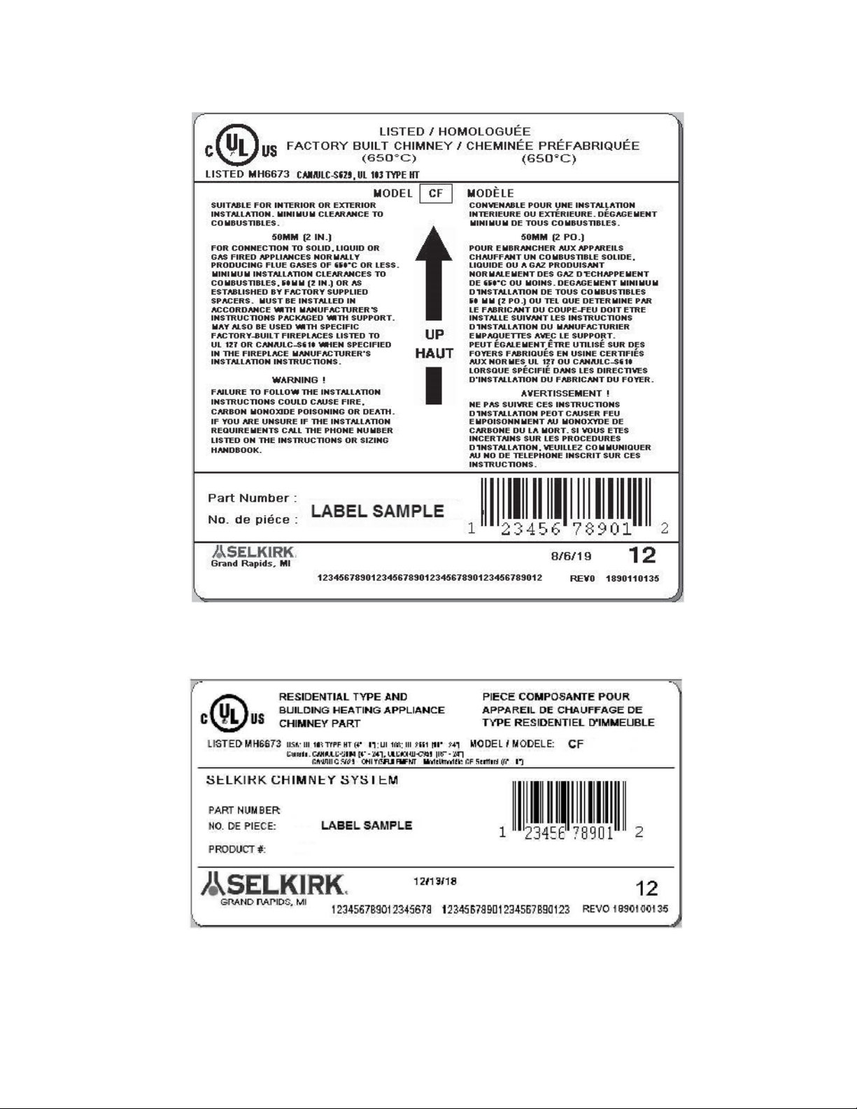
CERTIFICATIONLABELS
TYPES OF APPLIANCES
PRE-INSTALLATIONGUIDELINES
TOOLS
CFSENTINELJOINTSECURITY
FRAMING DETAILS
CEILINGSUPPORTINSTALLATION
SMOKE PIPE ADAPTER
FIRESTOPJOISTSHIELD
ATTICINSULATIONSHIELDINSTALLATION
ELBOWINSTALLATION
WALLSUPPORTINSTALLATION
WALL BAND
CATHEDRALCEILINGSUPPORTINSTALLATION
ROOFSUPPORTINSTALLATION
ROOFFLASHINGINSTALLATION
ROOFBRACEKITINSTALLATION
ROUNDTOP
SPARK ARRESTER
MAINTENANCEANDCLEANINGOFCHIMNEY
REPLACEMENTPARTSLIST
ANCHORPLATEFORMASONRYFIREPLACE
CHART1-OFFSETCHIMNEYINSTALLATION
CHART2-CHIMNEYHEIGHTABOVEROOF
CHART 3 - CONNECTOR PIPE CLEARANCE
INSTALLATIONRECORD
TABLE OF CONTENTS
3
CERTIFICATIONLABELS

4
10pds.
2pds.
min.
3 pds.
min. 2 pds.
Authorities require that the chimney extend not less than 3 feet
(900mm)abovethehighestpointwhereitpassesthroughtheroof
of a building and not less than 2 feet (600 mm) above any portion
of the building within 10 feet (3 m). See figure 1 and Chart 2.
The ideal location for your chimney is within the building
envelope. In cold climates, the use of external chimneys may
result in operational problems such as poor draft, excessive
condensation of combustion products and rapid accumulation of
creosote. Under these circumstances, the installation of the
chimney within the building is strongly recommended.
If the chimney must be installed on an exterior wall it is
recommended that the chimney be enclosed below the roof line
to protect the chimney from cold outdoor temperatures, this may
helpreducecondensation,creosoteformationandenhancedraft.
Provide an access door by the Tee Plug for chimney inspection
andcleaning. Theexteriorenclosuremaybeinsulated,maintaining
the required minimum air space clearance of 2" (50mm) to any
part of the chimney. Consult local building codes for cold climate
applications.
Do not install the chimney directly at the outlet of the appliance.
Interconnecting smoke pipe is required unless the appliance is
specifically approved for that type of installation.
Use only with an appliance listed by a recognized testing
authority such as Underwriters Laboratories Inc., Underwriters
Laboratories of Canada, Intertek Testing Services, Warnock
Hersey or ICBO.
The flue diameter of gas or oil fired appliances should comply
with the appropriate Installation Codes such as CAN/CSA-B139
or CAN/CSA-B149 when installed in Canada, and the Installation
Codes NFPA 54, ANSI Z223.1 and NFPA 31 in the United States.
WARNING: DONOTPLACE ANY INSULATING MATERIALSOR RUN ANY ELECTRICAL
WIRINGWITHIN THE REQUIRED AIR CLEARANCE SPACESURROUNDING THE CHIMNEY.
MAINTAIN A2"MINIMUM AIR SPACE CLEARANCE BETWEEN
INSULATED CHIMNEYSECTIONSANDCOMBUSTIBLEMATERIALS.
YourCFSentinelchimneyandconnecting stovepipediametershould
be sized in accordance with the appliance manufacturer’s
recommendations.
Plan the installation of your appliance and chimney in such a way that
both your chimney and your chimney connector (stovepipe) run is as
short and straight as possible. By having too long and / or multiple
bend installations you can reduce system draft which can affect the
operation, and or performance of your appliance and or the chimney
system. Thechimney shouldbelocatedwithinthebuildingastoavoid
cutting or altering load bearing members such as joists, rafters, studs,
etc. Ifyouhavetocutoralteranexistingloadbearingmember,special
reframing methods are required which often include doubling of
adjacent members. If such a case arises, contact your local Building
Code Official regarding local regulations and proper installation
methods.
Before commencing the installation ensure that you obtain any
necessary building permits, and that your installation will conform with
all federal and municipal building codes requirement.
Sections of the CF Sentinel chimney which pass through accessible
areasof thebuildingsuch asthroughclosets,storageareas,occupied
spaces or any place where the surface of the chimney could be
contacted by persons or combustible materials must be enclosed in
a chase. The chase may be fabricated using standard building
materials. Drywall mounted on 2” x 4” studs is typically used in this
situation. Except for installation in single and two family dwelling,
factory-built chimneys shall be enclosed with approved walls having
a fire resistance rating equal or greater than that of the floor or roof
assemblies through which they pass. The space between the outer
wall of the chimney and the enclosure shall be at least 2 inches.
TYPES OF APPLIANCES
PRE-INSTALLATION GUIDELINES
If you have a basic knowledge of carpentry and how to use hand
tools, taking on the task of installing your new venting system will
beeasy. However,itisimportantthattheseinstallationinstructions
are followed. If you choose to have your product professionally
installed, we recommend these products be installed by
professionals who are certified in Canada by WETT (Wood
Energy Technology Transfer) or l'APC (l'association des
professionels du chauffage) or NFI in the US.
Be sure that ladders are in good condition and always rest on a
level firm surface.
Be sure that electrically powered tools are properly grounded.
YOUR CHIMNEY HAS BEEN TESTED, AND LISTED USING
ALL OF THE SUPPORTS, SHIELDS, ETC., DESCRIBED HEREIN.
DELETION OR MODIFICATION OF ANY OF THE REQUIRED PARTS OR
MATERIALS MAY SERIOUSLY IMPAIR THE SAFETY OF YOUR INSTALLATION,
AND VOID THE CERTIFICATION AND OR WARRANTY OF THIS CHIMNEY.
FIGURE 1
3 ft.
min.
CANADAAPPLICATIONS
Your CF Sentinel chimney has been tested per CAN/ULC-S629
as an all fuel chimney. As such it is code approved for connection
to solid, liquid or gas fueled residential type appliances and
building heating appliances in which the maximum continuous
flue gases temperatures do not exceed 650°C (1200°F). It has
also been tested and approved to withstand temperatures of up
to 2100°F for three thirty minutes intervals.
The installation should be in accordance with the Installation
Code CAN/CSA-B365 (Solid-Fuel-Burning Appliances and
Equipment) and / or the National Building Code of Canada and
Provincial Building Code, etc. should be consulted.
May also be used with specific factory-built fireplaces listed to
UL 127 and CAN/ULC-S610 when specified in the fireplace
manufacturer's installation instructions.
U.S.A. APPLICATIONS
The CF Sentinel chimney has been tested per UL-103 as "Type
HT". As such it is code approved for connection to solid, liquid
or gas fueled residential type appliances and building heating
appliances in which the maximum continuous flue gases
temperatures do not exceed 1000°F. It has also been tested and
approved to withstand temperatures of up to 2100°F for three ten
minutes intervals.
Theinstallationshould be in accordancewith NFPA211(Standard
for Chimneys, Fireplaces, Vents and Solid Fuel fired Appliances),
and / or local and regional codes such as the International
Mechanical Code and Uniform Mechanical Code, etc.
WEAR SAFETY GLOVES WHEN HANDLING
SHEET METAL PARTS WITH SHARP EDGES
CONTACT LOCAL BUILDINGOR FIREOFFICIALS ABOUT RESTRICTIONS AND
INSTALLATIONINSPECTION INYOURAREA.
5
AB
6" 141/4" x 14/4"
362mm x 362mm
8"
7"
141/2" x 141/2"
369mm x 369mm 141/2" x 141/2"
369mm x 369mm
141/4" x 14/4"
362mm x 362mm
141/4" x 14/4"
362mm x 362mm 153/4" x 153/4"
400mm x 400mm 153/4" x 153/4"
400mm x 400mm
17" x 17"
432mm x 432mm 17" x 17"
432mm x 432mm
WebCoupler*
*Not exactly as shown.
Situate the chimney in the structure so that it can be installed
without cutting joists, sills, plates or load bearing partitions or
members.
Connect only one appliance to a chimney.
There should be no draft regulators on solid fuel equipment and
smoke pipe connector.
A minimum smoke pipe connector length of 3 feet (1 m) between
appliance and chimney is recommended.
Your CF Sentinel chimney system is designed for installation
using standard building materials and procedures. The following
tools may be required:
TOOLS
-safety gloves
-safety goggles
-hammer and nails
-tin snips
-tape measure
-screwdriver and pliers
-plumb line and level
-square
-keyhole saw or power jig saw
-caulking gun
Other tools or equipment may be required, depending on your
chimney location and the structure in which it is to be installed.
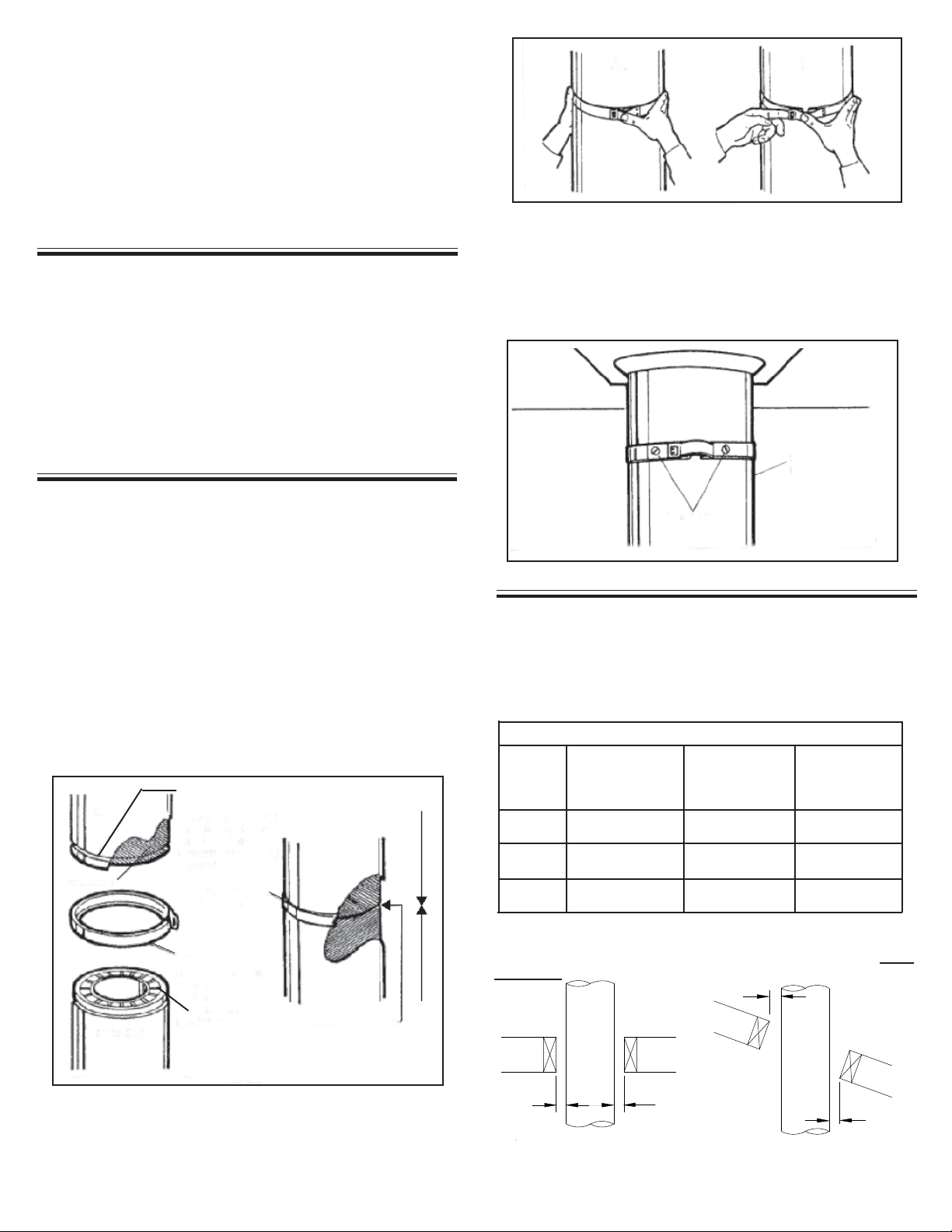
CF SENTINEL JOINT SECURITY:
High internal gas temperatures in a chimney force the internal
pipe to expand or lengthen. This, in turn, may cause the joints
to separate if they are not securely locked. The use of a chimney
cleaning brush may also cause the joints to separate if not
securely locked.
INSULATION COMPRESSION OF THE CF SENTINEL
Beforeassembling chimney lengths to one another, the insulation
on the female end (held in place with a plastic retainer) should be
below the outer bead so that it can compress during assembly.
The upper side (male end), should be full of insulation (held in
place with a white paper retainer and a web coupler) to the top of
the length. Once you have assembled the lengths together, a
locking band must be installed. With the insulation being
compressed, this will provide insulation to insulation contact (see
Figure 2).
NOTE: Whentheinsulation retainersmeltorvolatilize duringhigh
temperature operation, the compressed insulation will fill in.
FIGURE 2
Insulation
Locking Band
Locking Band
SeatedAll
Around
InsulationtoInsulation
Contact
InsulationCompressed
Outer Bead
SuspendedLength
Stainless Steel
SheetMetal
Screws FIGURE 4
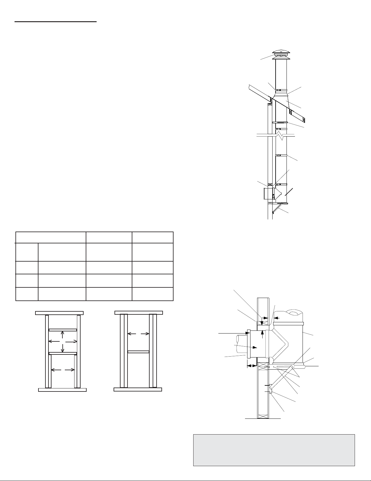
Plan your installation carefully. If possible, position the stove so
that the flue outlet is centered between joists or rafters. Drop a
plumb line to the center of the flue outlet and mark this center
point on the ceiling. Lay out and frame in all openings ensuring
the specified 2” clearance to combustibles is maintained. Refer
to Table 1 or applicable Tables for framing dimensions and mark
the appropriate cutting lines around the center point.
FRAMINGDETAILS:
2. To remove the lockband, the clasp is pushed in and then
unhooked (see Figure 3B). Lift the clasp with a screwdriver if
necessary.
3. When a chimney section is suspended e.g: below a Cathedral
Ceiling Support, the band(s) and the joints must be fastened
using two (2) #6 x 1/2" stainless steel sheet metal screws (see
Figure 4).
FIGURE 3
INSTALLING THE LOCKING BAND:
NOTE: The chimney pipe and fittings must be assembled only
with the locking bands as furnished.
1. The clasp lockbands are simply seated in the beads of the
joints and clipped together (see Figure 2 & 3A). Typical Roof
Joist Framing
FIGURE 5
Typical Joist
Framing
2"Min.
2"Min.
2"Min.
2"Min.
FIGURE 6
TABLE1
*Note: The clearance to combustibles obtained with a correctly
installed Ceiling Support Assembly in the framed opening
specified above has been tested. The 2 inch clearance does
not apply at this location.
*Ceiling
Support Wall
(Support)
Thimble
FramingDimensions
All Other
Framing
Chimney
Flue
Diameter
6
Trim Plate
Ceiling
Support
Nailing Holes
3 Nails per Sides
(4 sides)
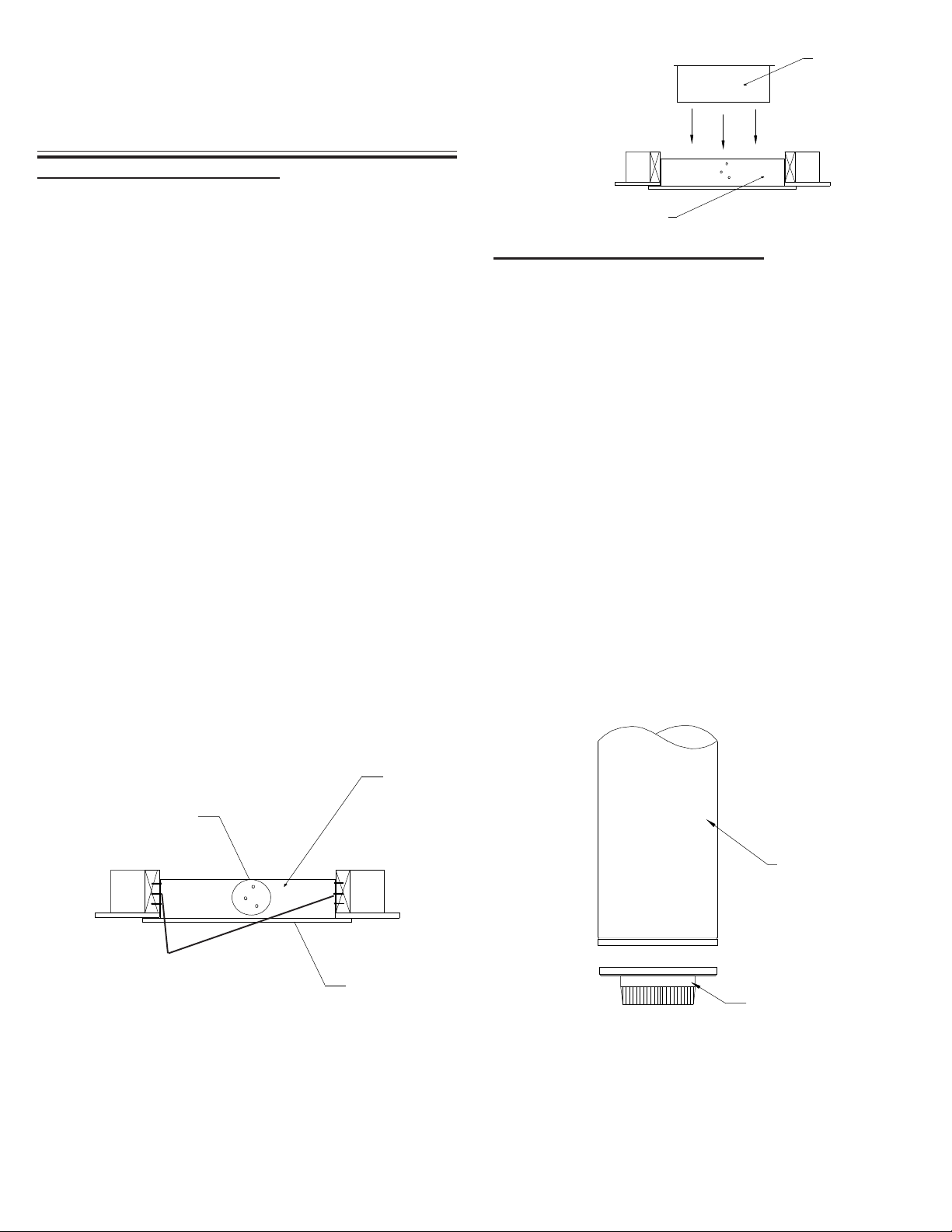
CEILING SUPPORT (CBSP)
- Suitable lengths of Chimney: - The chimney diameter should be
sized to suit the appliance.
- 15oor 30oChimney Elbow: - and suitable supports; resupport
assembly or roof support if required.
- Round Top: - To exclude rain and/or debris into the chim-
ney.
To complete a proper Ceiling Support installation, the following
parts will or may be required:
- Ceiling Support: - Required when supporting chimney with a flat
ceiling.
- Attic Insulation Shield: - Required where a chimney passes into
an unoccupied attic space.
- Firestop Joist Shield: - Required where a chimney passes from
a lower living space into an upper living space or occupied attic
space
- Roof Flashing Assembly: - Required where the chimney
penetrates a roof.
INSTALLATION PROCEDURES:
TheCFSentinel Ceiling Support will support up to 40feet(12.2m)
of chimney sections, all of which must be installed above the
support. Figures 10 & 11 illustrates the 2 most common types
of Ceiling Support Installation.
Frame (on all 4 sides) a level square opening with the inside
dimensions 14-1/4" (362 mm) square.
With the Lower Bucket removed, place the Ceiling Support
Assembly into the framed opening from below at the ceiling level
(see Figure 7).
The stub end (crimped) of the Smoke Pipe Adapter is intended
to fit inside of the connector pipe from a solid fuel appliance, thus
preventing condensate drips at the chimney connection.
Install inter-connecting stove pipe following appliance
manufactruer's instructions and appropriate building code re-
quirements keeping in mind that the stove pipe run should be as
short and straight as possible and secured in place with a
minimumof 3sheetmetalscrews per joint. Generally, for a wood
burning appliance installation, an 18" minimum clearance to
combustibles must be maintained for the stove pipe. NOTE: The
exception to this is a double wall stove pipe, such as Selkirk's
Model DSP which can be installed at reduced clearances to
combustibles. See separate installation instructions for more
details.
FIGURE8
SMOKE PIPE ADAPTER (SPA)
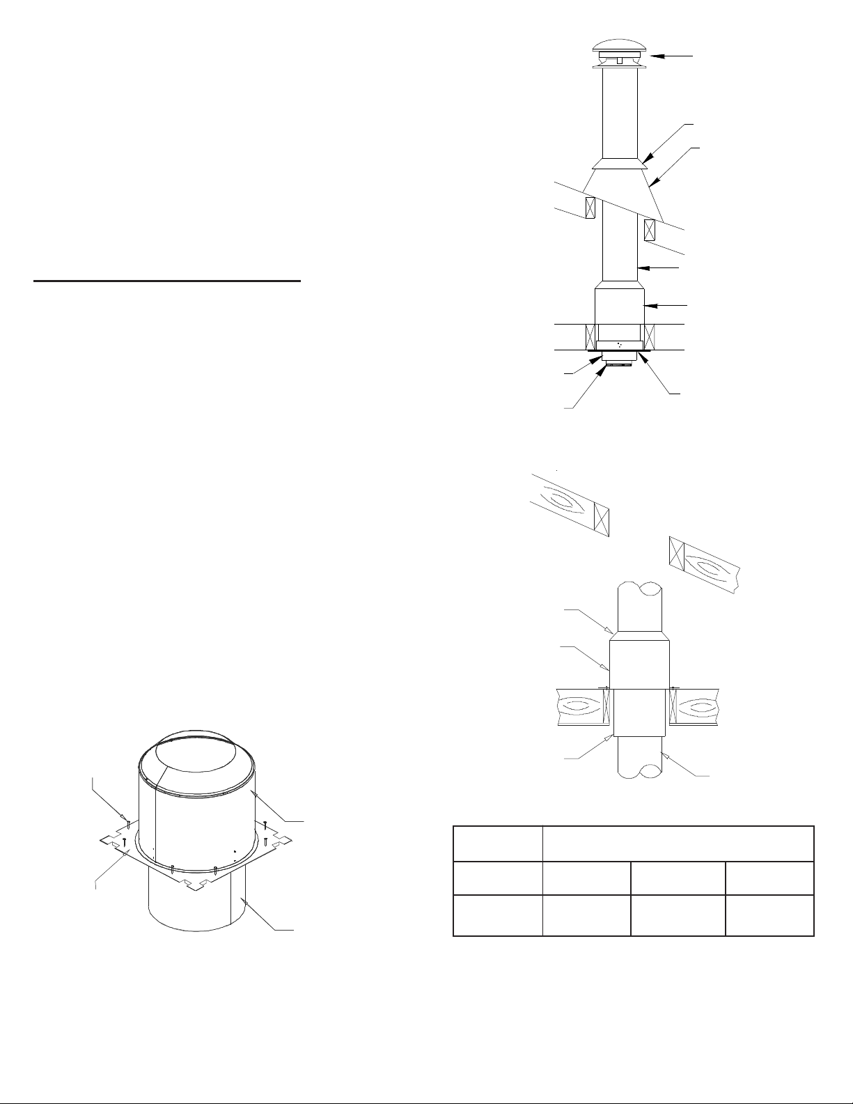
FIGURE 7
Basecap w/ Built-In
Smoke Pipe Adapter
Chimney
Length
Finish nailing through all the pre-punched holes (12 nails total)
and fasten the finishing plate onto the ceiling with the 4 supplied
black wood screws. Replace the Lower Bucket into the Ceiling
Support (see Figure 8).
Drive one nail, 1-1/2" common or spiral, part way into each of the
four (4) nailing areas of the support. Check that the trim plate is
level and flush (see Figure 7). You may substitute in lieu of nails
#8 x 1-1/2" wood screws.
Lower Bucket
Insert the Lower
Bucket into the
Ceiling Support
BEFORE LOWERING THE FIRST CHIMNEY LENGTH:
The Basecap Assembly with the short crimped Smoke Pipe
Adapter must be inserted into the female end of the first length
(see Figure 9a).
-Insertthe short portion of the short crimped Smoke PipeAdapter
into the Basecap.
- Ensure the Basecap portion is located on the inside of the
exterior casing of the insulated chimney (flush to the bottom of
the inward bead) and the Smoke Pipe portion is located over the
inner liner of the Chimney Length (see diagram 9b).
FIGURE9a
Installed Ceiling Support
All openings should be square (all four sides), plumb and in
perfect alignment with each other (see figure 5).
Forslopingroofsand/orceilings,ensurethattheframingdimension
is measured in the horizontal plane (see figure 6).
7
3"
4-1/8"
2-1/2"
2-1/2"
4-1/8"
3"
FIGURE11
Floor, Ceiling Joist
(Framed all 4 sides)
Lower Bucket
FIGURE9c
TrimPlate
Smoke Pipe Adapter
Lower Bucket
CeilingSupport
Lower the prepared Chimney Length into the Lower Bucket.
Ensure that the Chimney Length rests on the Lower Bucket into
the Ceiling Support (see Figure 9c).
NOTE: Any length of CF Sentinel Chimney can be used.
There is no special "Starter" length required with the
Ceiling Support. Make sure the length is long enough to be
above the floor level or above the Attic Insulation Shield.
Continue adding chimney lengths until a height of about 2 feet
below the next ceiling level is achieved.
Chimney
Length
Inner Liner
of Chimney
Length
Insulation between
Outer Casing and Inner
Liner of Chimney
Length
Basecap Portion
(painted black)
Short crimped Smoke
Pipe Adapter Portion
Outer Casing of
Chimney Length
FIGURE9b
Inward bead of
outer casing
Beveled Portion Up
Crimpedend
Towards Appliance
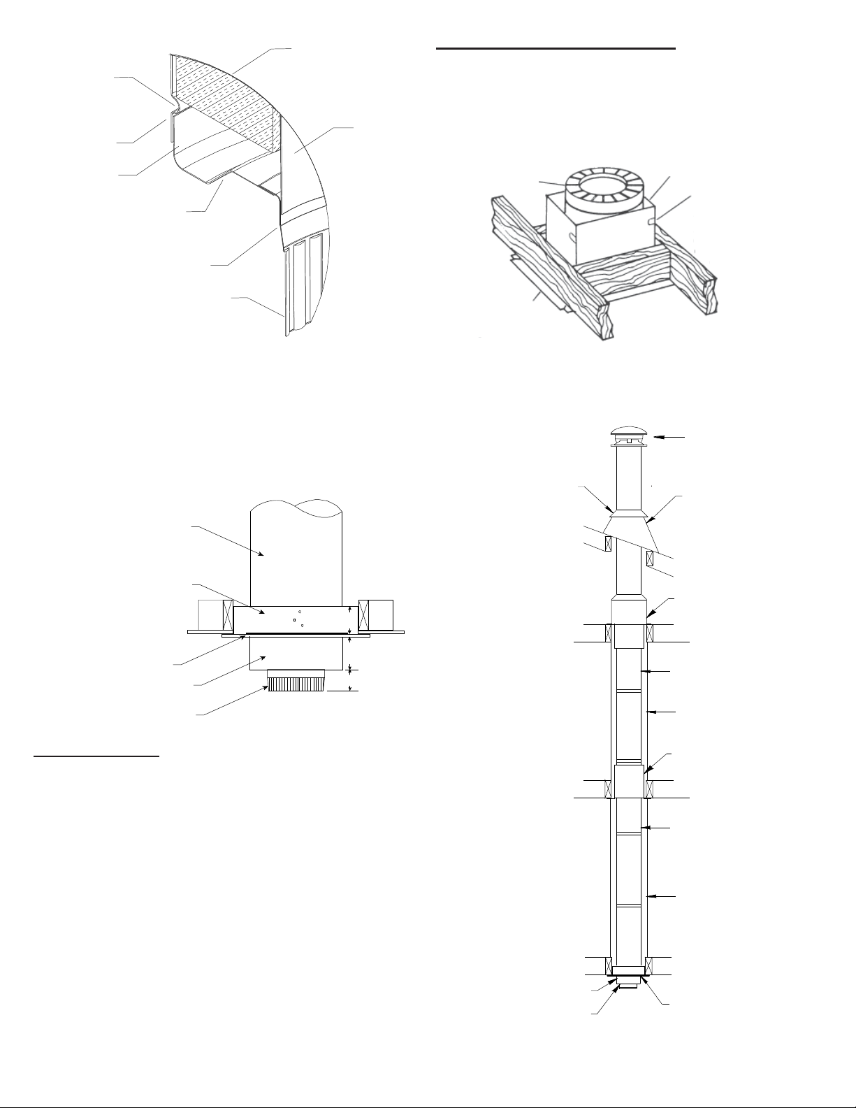
FIRESTOP JOIST SHIELD (JS)
A Firestop Joist Shield (JS) must be installed where the
chimney passes from one living space to another living space as
shown in figure 11. It is designed to provide proper firestopping
between floors and to keep direct radiation from the chimney away
from the joist framing.
RoundTop
StormCollar RoofFlashing
Attic Insulation
Shield
FramedEnclosure2"(50mm)
clearance from chimney to
combustiblewall
ChimneySections
ChimneySections
Living Space
Attic Space
Floor, Ceiling Joist
(Framed all 4 sides)
Floor, Ceiling Joist
(Framed all 4 sides)
Roof Joist
(Framed all 4 sides)
Two Story
Basement Installation
CeilingSupport
Living Space
FramedEnclosure2"
(50mm)clearancefrom
chimney to combustible
wall
Smoke Pipe Adapter
Firestop Joist Shield
FIGURE10
Firestop Joist
ShieldPositioned
intoFramingfrom
below
CloseBox Corners
UsingTabs
ChimneyLength
NailSideFlanges
Securely To Bottom
ofFraming
FIRESTOPPING
Firestopping is required at every joist level. Wherever a chimney
passes through a ceiling or floor, through a wall, or into an
enclosure, it must be firestopped. No firestopping is required in
conjunction with a Ceiling Support installed as shown in Figures
11, the Ceiling Support provides the firestopping.
A fire stop performs the following essential functions for both
dwelling and the chimney:
- Together with a fully framed opening (all four sides), it controls
vertical and horizontal spread of any fire external to the chimney.
- It stabilizes the chimney in the framed opening and defines and
maintains the required AIR SPACE clearance to combustibles.
- It reduces heat losses from the dwelling by blocking vertical air
circulation in the spae around the chimney.
- When located at a ceiling below a roof flashing (or below a roof
support) it helps provide stability for chimney extending above the
roof.
- At the level where the chimney penetrates the air/vapour bariier,
special attention is required. Seal the vapour barrier to the Ceiling
Support, Attic Shield (Joist Shield if the chimney is enclosed in the
attic) or Wall Thimble using an appropriate caulking compound as
per the requirement of local authorities.
8
14-1/4 x14-1/4
362 x 362 16-3/4 x16-3/4
426 x 426
15-1/2 x15-1/2
394 x 394
6" 7" 8"
The Attic Insulation Shield (AIS) provides 2 features: it comes
fully assembled with a built-in telescoping bottom shield,
eliminating the need for field assembly.The function of the Attic
InsulationShield(or a complete enclosure) is to keep insulation from
coming into contact with the chimney. Certain insulations made
of cellulose fiber (old newspapers, processed wood) may ignite
and smolder due to heat trapped by contact with the chimney.
When this smoldering fire reaches ordinary wood framing, a
flaming fire may resuilt. However, even without a flame, a
smoldering fire may create noxious gases and cause great
property damage.
An Attic Insulation Shield (AIS) must be installed where the chimney
enters an attic space. The Attic Insulation Shield is designed to
keep insulation materials from coming into contact with the chimney
and will protect up to a 10 inch 250mm) thickness of insulation plus
thedepth of the ceiling joists. If insulation is blown in and adheres
to the chimney pipe, it should be brushed off to eliminate any
possible contact of this material with the chimney when it is in
use.
The height of the AIS must accomodate the amount of insulation
as required by the National Building Code. Where height
restrictions will not permit the use of the Attic Insulation Shield, it is
permissible to construct an enclosure with the required minimum
air space clearance of 2" (50mm) to the chimney all the way to the
underside of the roof deck. In this application you will install a
Firestop Joist Shield (JS) at the ceiling level, with the exception of
a Single Story Installation (see Figure 13).
ATTIC INSULATION SHIELD (AIS)
Nail the AIS base to the framing dimensions with at least 2 per
side using 2d (1") spiral nails or 1" x #8 wood screws.
FramingDimensions
forAtticInsulationShield
DIAMETER
OFCHIMNEY
TABLE2
FRAMED
OPENING
Single Story
Installation
Attic Space
Roof Flashing
SmokePipeAdapter
RoundTop
StormCollar
ChimneySections
Attic Insulation Shield
CeilingSupport
Ceiling Joist
(Framed all 4 sides)
FIGURE13
Roof Joist
(Framed all 4 sides)
Lower Bucket
FIGURE 14 - Attic Insulation Shield
Fully frame a level square opening (all four sides) for 2" ( 50mm)
clearance from the outside of the chimney to the inside of the
frame. Place the Firestop Joist Shield (JS) up into the framed
opening from below the joist framing and nail in place using 1"
spiral nails as per Figure 10. Ensure no insulation or debris is
within the 2" air space clearance around the chimney. This
includes the air spaces between the Firestop Joist Shield (JS)
and the joist framing.
When the chimney is enclosed in the attic area, a Firestop Joist
Shield (JS) must be installed at the ceiling level. If the base of the
Firestop Joist Shield (JS) does not fit flush with the ceiling frame,
measure the distance that the base is sitting below the framing
and trim that amount off the top of the Firestop Joist Shield (JS)
before securing into place.
Attic Insulation
Shield(AIS)
Telescoping
Joist Shield
Nail Base to
Framing
Base (Fire Stop)
FIGURE12
Attic Insulation Shield
Intergrated Storm Collar
Telescoping Joist Shield Chimney Section
Attic space
For proper installation, the attic opening must be fully framed at
2 inches of clearance to the chimney pipe with framing material
of the same dimension as the ceiling joists (as per Framing
Dimension Table 2). The tabs on the base plate of the AIS are
inserted in the framed opening around the chimney. NOTE: This
only applies to the 6" AIS. On the 7" and 8" AIS, the tabs will
require to be flattened out and the AIS centered over the
framed opening.
When an Attic Insulation Shield is required above the Ceiling
Support into an attic as shown in Figure 13, ensure that the base
of the shield is flush with the top of the joist framing and nailed in
place. The telescoping portion of the AIS will eliminate the need
to trim the bottom when installed immediately above this support.
When fully exended, the AIS will also provide joist shielding when
installed in a 2 story main floor or basement applications (see
Figures 11 & 15).

9
SmokePipeAdapter
Elbow
ElbowSupportBand
Locking Bands
Elbow
Ceiling Joist
(Framed all 4 sides)
Floor, Ceiling Joist
(Framed all 4 sides)
RoundTop
StormCollar Roof Flashing
ChimneySections
Roof Joist
(Framed all 4 sides)
Elbow Support Straps
Locking Bands
CeilingSupport
Living Space
Attic Space Attic Insulation Shield
Offset(Elbow)Installation
FIGURE16
Lower Bucket
FramedEnclosure2"(50mm)
clearance from chimney to
combustiblewall
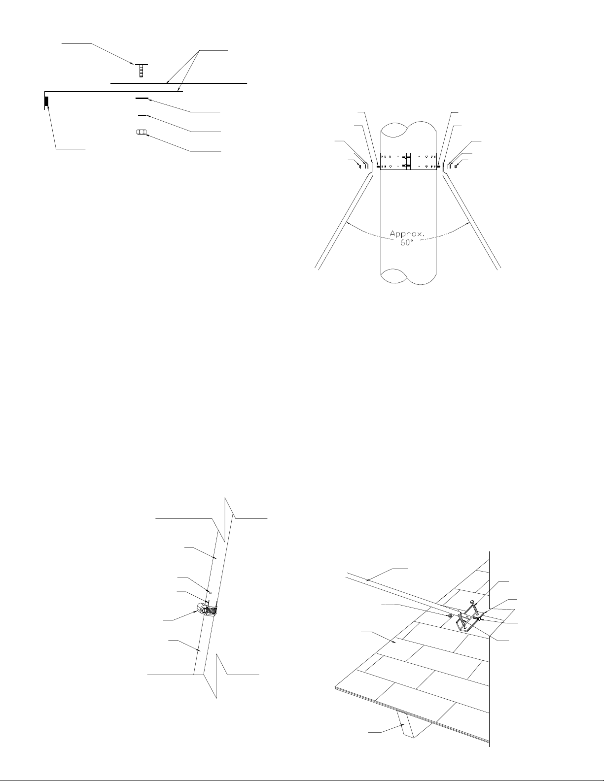
Install a Resupport Assembly on the vertical length just above the
highest elbow. Securely clamp the Support Band to the chimney
just above the locking band at the joint. Attach the Support Straps
to the Support Band assembly and nail the Support Straps to the
framingusing 1-1/2”nailsor#8x1-1/2"woodscrews (2perstraps).
See Figures 17 and 18.
The weight carrying capacity of the support, which depends on
the angle of the straps, and the security of attachment is
adequate for 9 m (30') of Model CF Chimney pipe.
ELBOW INSTALLATION
Framed Enclosure 2" (50mm)
clearance from chimney to
combustible wall
Living Space
Roof Flashing
CeilingSupport
Smoke Pipe Adapter
RoundTop
Storm Collar
Floor, Ceiling Joist
(Framed all 4 sides)
Ceiling Joist
(Framed all 4 sides)
Attic Insulation Shield
Attic Space
Chimney Sections
Two Story
Main Floor Installation
Roof Joist
(Framed all 4 sides)
Lower Bucket
NOTE:Toreducecoldairinfiltrationintothedwelling you can
installtheoptionalUniversalShieldingInsulation(SUSI)
into the Attic Insulation Shield. See separate installation
instructions.
FIGURE15
NOTE: At the level where the chimney penetrates the air / vapour
barrier,specialattentionisrequired. Sealthevapourbarriertothe
Ceiling Plate of the Ceiling Support, Wall Thimble or Attic
Insulation Shield using an appropriate caulking compound as per
the requirement of local authorities.
StainlessSteel
SheetMetal
Screws
FIGURE18
Two pairs (four) of 15oor 30oelbows may be used in an interior
installation to provide an offset in order to avoid cutting of joists and
to clear other obstructions.
Locking bands must be used at each joints. For added security
when forming an offset, it is required to fsten the joints using two
(2) X6 x 1/2" stainless steel sheet metal screws through the pro-
punched holes in the locking bands (see Figure 16).
The maximum permissible angle with solid fuel CF installation is 30
degrees. Combiningoffsetsforgreaterangleisnotpermitted. The
vertical run of chimney above an offset must be supported using an
Interior Resupport Assembly. Each Interior Resupport Assembly
will support 30 feet (9 m) of chimney and the maximum length of
chimney allowed between the elbows is 6 feet.
See Chart 1 for Offset Chimney Installation at the back of these
instructions for more information.
Never install an elbow in a joist area. Chimney sections must
pass vertically through a framed joist areas.
During installation provide supplementary support for the offset
section to avoid undue stress on connected elbows.
SupportBand
Straps
Locate Support
BandBelow
Locking Band at
Joint
Bend Straps
Over Framing,
Nail Securely
FIGURE17
10
EF
F
E
11-1/2" (292mm)
12-3/4" (324mm)
14" (356mm)
14-1/2" (369mm)
15-3/4" (400mm)
17" (432mm)
10-5/8" (270mm)
11-7/8" (302mm)
13-1/8" (334mm)
6"
7"
8"
F
WALL SUPPORT (WSP)
To complete a proper Wall Support installation, the following parts
may be required:
- Wall Support Package: - Intended for a through-the-wall installa-
tion where the chimney has a lateral connection.
- Adjustable Roof Flashing: - Required when the chimney
penetrates a roof or a roof overhang.
- Insulated Tee: - Required when the chimney is installed through
and along a vertical wall either on the exterior or interior.
- Wall Bands: - Required to provide lateral support to the chimney.
- Suitable lengths of chimney: - The chimney diameter should be
sized to suit the appliance.
- Interior Wall Plate and Exterior Wall Plate: - Required when going
through a combustible wall.
- Insulated Wall Thimble: - Required to satisfy through-the-wall
installation where framing an opening may not be practical.
- Round Top: - To exclude rain and/or leaves into the chimney.
The CF Sentinel Adjustable Wall Support will support up to 40 feet
(12.2 m) of chimney, all of which must be above the support.
1. Determine the center line of the lateral connection (horizontal
length through the wall) and frame in your opening to the dimen-
sions specified in Table 3. For a non-combustible wall (concrete
blockor pouredfoundation),cutahole 1/8"greaterthantheoutside
diameter of the chimney as per Table 3. DO NOT PLACE ANY
LOOSE INSULATION around the horizontal chimney length within
the framed opening when using a Wall Plate Spacer or Insulated
Wall Plate Spacer. Maintain the required minimum 2" (50mm) air
space clearance to combustible materials.
2. Assemble braces, brackets and angles to the base plate using 1/
4" nuts and bolts, with braces up or down as necessary (DOWN IF
CHIMNEY GOES THROUGH WALL) as per Figure 19 & 20a and if
it is an interior wall support installation (Figure 20b).
3. Nailbracketsand angles to framing temporarily making sure that
the base plate is level (and positioned to allow for the installation
of the wall plates, if the chimney goes through the wall).
TABLE3
Chimney
Size Hole
Non Combustible Framed Opening
Combustible Framing
For Bracing
A.
Framingforthroughthewall
InsulatedTee
B.
FramingforTeefacingaway
fromthewall
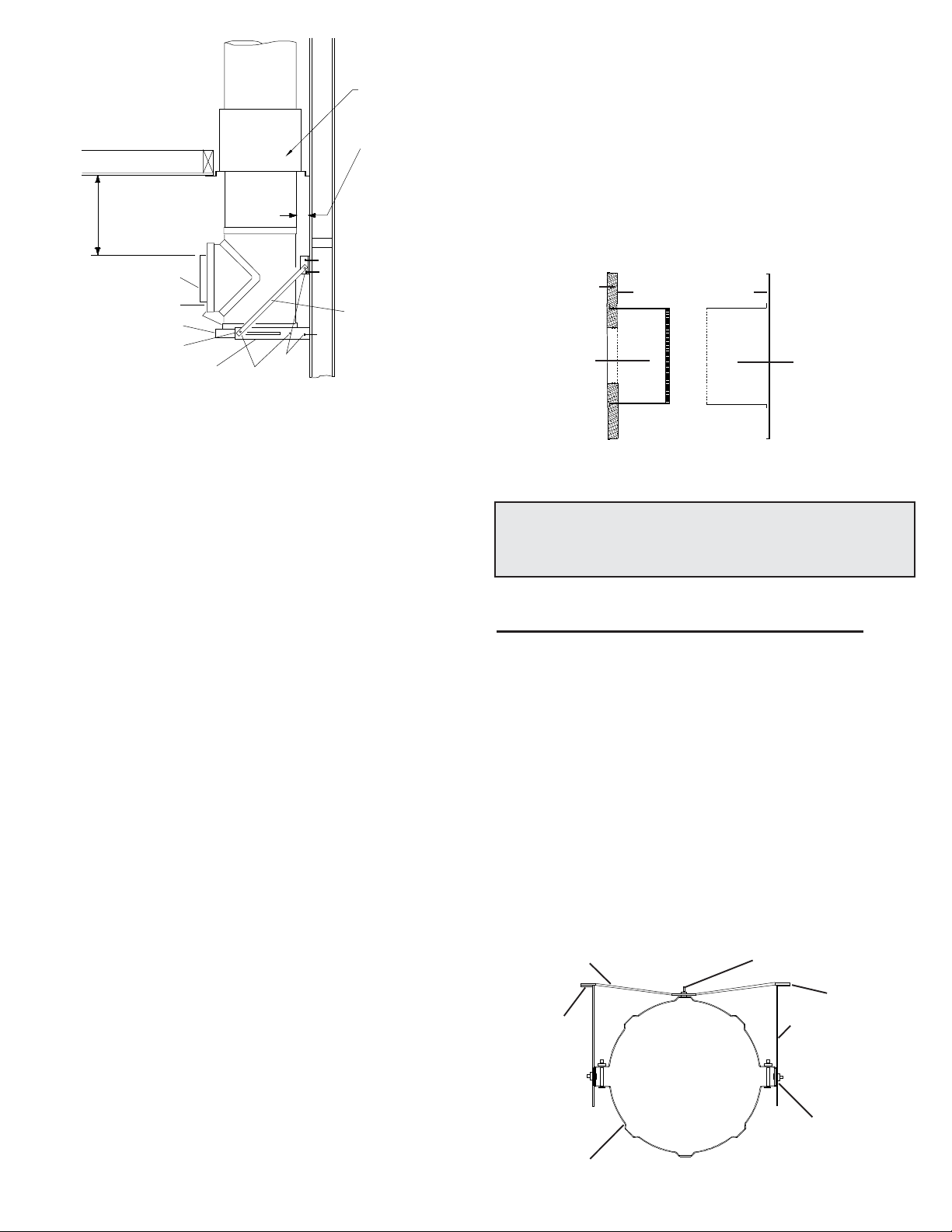
6. If the Tee is located on an outdoor wall, place the exterior wall
plate over the horizontal Tee branch, and attach an appropriate
insulated chimney length to the Tee branch. Secure in place with
the supplied locking band. Ensure that the clasp of the locking
band is facing down to prevent any water from collecting in the
lockingbandiflockingbandispositioned on the exterior of the wall.
NOTE: Interior or Exterior Plates can be substituted with the
Insulated Wall Thimble. In a combustible wall the opening must
be framed in (see Table 3).
Round Top
Storm Collar
Roof Flashing
Wall Plate Spacer
Wall Band
Locking Band
Exterior Wall
Plate (Louvered)
Insulated Tee
Angle Bracket
FIGURE19
4. Mark, and drill 5/32" pilot holes in the framing for the lag screw
location, or install masonry anchors in proper locations.
5. Remove nails, install lag screws or anchor bolts in all the holes
and tighten all bolts in the assembly.
FIGURE20A
ExteriorWallSupport Installation
Base Plate
Bolts
Angle Brace
Wall Bracket
Wall Angle secured to studs
with lag screws
Lag screws
Insulated Tee
Locking Band
Tee Plug with lugs
Exterior Wall Plate (louvered)
Maintain 2"
(50mm)
Min. clearance
Wall Plate Spacer
Locking
Band
9" Pipe Section
Min.
3" (76mm) Min.
39" (990mm) Max.
NOTE: THE CHIMNEY MUST EXTEND AT LEAST
3” (75 MM) INTO THE LIVING SPACE WHERE THE
SMOKE PIPE ADAPTER WILL BE ATTACHED TO THE
CHIMNEY BRANCH.
Locking Band
Smoke Pipe
Adapter
11
NOTE: If complete framing of the vertical wall opening is not
practical, the Wall Plate Spacer and the Exterior Wall Plate must
be substituted with an Insulated Wall Thimble (see Figure 21). It
is designed for use in accommodating unframed openings while
maintaining thechimney'srequired50mm(2")airspaceclearance
to combustibles.
- Install the Wall Thimble before installing the Wall Support
assembly.
- Ensure that the proper framing dimensions is respected below
the opening to accommodate the Wall Support (see F "Framing
for Bracing" in Table 3).
Interior Wall Support Installation
FIGURE20B
Insulated Wall Thimble
FIGURE21
Tee Plug retained by twist lugs
WallBracket
BasePlate
LockingBand
SmokePipeAdapter
BaseCap
Bolt Lag
Screws
AngleBrace
Refer to the Installation
Codes for clearance to
single wall pipe.
Normally 18" (450mm)
minimum clearance is
required for solid fuel
fired appliance.
2" (50mm)
Minimum
Clearance
Interiorportionof
InsulatedWall
Thimble
Exteriorportionof
InsulatedWall
Thimble
Telescoping adjustment
from 6" to 11"
InsulationBlanket
NOTE: To reduce cold air infiltration into the dwelling
you can install the optional Universal Shielding Insula-
tion (SUSI) into the Insulated Wall Thimble. See sepa-
rate installation instructions packaged with the SUSI.
WallBand
FIGURE22
1-3/4"CarriageBolt
Strap Under
WallBracket
Perforated Straps
LagScrews
Support Band
WallBracket
Pivot Screw In Slot
WALL BAND INSTALLATION (WB)
1. The required 2" (50mm) minimum clearance is established by
the 1-3/4" center (carriage) bolt. Place the 1-3/4" carriage bolt
through the center offset of the band half nearest the wall. Place
single hole ends of the perforated straps over this bolt. Install nut
tight against strap so that straps are horizontal (as per Figure 22).
2. Clamp the two halves of the support band around the chimney
pipe using the long bolts through the band end tabs. First install
the pivot screws.
3. Place the wall brackets (long slotted parts) over the pivot
screws projecting out from the end tabs and hand tighten.
4. Line up the perforated straps and wall brackets, then mark
position on wall for lag screws or anchors to go through both the
straps and brackets.
9. After checking fit, secure Tee to integral basecap of base plate
with a locking band. Install the Tee Plug and turn the two (2) twist
lugs.
10. Use a non-hardening high-temperature sealant (500oF) to
seal around the exterior portion of the horizontal chimney length
where it enters one of the following: Exterior Wall Plate, Insulated
Wall Thimble or a concrete wall.
11. NOTE: Only CF Sentinel chimney must extend through-the-
wall. Use the Wall Plate Spacer (or the interior portion of the
Insulated Wall Thimble) on the interior wall to center and support
the horizontal extension. Remember that the chimney pipe
length selected must extend at least 3" (76mm) beyond the wall
and must be centered in the wall opening. The maximum length
of pipe out from the wall is 39" (990mm).
12. Chimney lengths above the Tee are simply stacked and
secured in place with the supplied Locking Bands.
13. To ensure chimney stability above the wall support, Wall
Bands must be used at every 8 to 12 feet (2.4 to 3.6m) intervals
above the support.
8. If the Tee and the Chimney will be fully enclosed in a chase or
shaft or the wall is non-combustible, the exterior wall plate need
not be used.
7. Place this whole assembly (Insulated Tee, Chimney Length
and Exterior Wall Plate) into the wall opening and onto the base
to check centering and clearances. Make sure there are no
interferences. If the Tee is outdoors, keep in mind that the louver
openings in the Exterior Wall Plate must be down to keep the rain
out.
Firestop Joist
Shield Installed
at Ceiling
Level
- If wall thickness is less than 6 inches, trim round inner shield
accordingly.
- Install thimble before installing the Wall Support assembly.
- Insert the 2 halves from opposite sides of the wall. The painted/
insulated section is to be installed from the interior side. Secure
using the supplied black screws.
- The unpainted/exterior half has the larger diameter shield and
simply slides over the interior half. Fasten to wall with suitable
fasteners.
- Seal the perimeter of the exterior plate using an appropriate
exterior sealant.

12
The bottom chimney length(s) must protrude into the living space
so that proper clearances are maintained from the stove pipe
connector to the lower side of the ceiling (see Chart 3 in the back
of these instructions for more details). Do not offset the CF
Sentinel chimney below the Cathedral Ceiling Support Box.
Install additional chimney lengths with locking bands until the
required height above the roof is achieved. NOTE: As previously
mentioned, when a chimney is suspended below the box, locking
bands and joints must be fastened using two (2) #6 x 1/2"
stainless steel sheet metal screws (as per Figure 4).
CathedralCeiling
SupportInstallation
FIGURE23
StormCollar
Roof Brace Kit
RoundTop
RoofFlashing
SmokePipeAdaptor
CF Sentinel chimney to be a
minimum distance of 4"
(101.6mm) below Support Box
Support Band
ROOF SUPPORT (URSA)
50mm(2")MinimumAir
SpaceClearance
DecorativeAdapter
CathedralSupportBox
Install the Support Band on the chimney length at the desired
position by assembling the support bands using the 2 carriage
bolts and nuts. NOTE: A minimum of 4" of an insulated
chimney length must protrude below the Cathedral Support
Box for stability (see Chart 3 at the back of these instructions
for more details). Snug nuts to bolts, do not over-tighten so that
the band deflects the chimney outer casing. Secure the band to
the chimney outer casing by screwing the eight (8) stainless
steel sheet metal screws through the draw band and into the
outercasing (for ease of attachment use a 3/32" hole). Lower the
chimney length down through the opening in the bottom of the
Support Box, so that the Support Band makes contact with the
bottomoftheSupport Box (See Figure 23).NOTE: The maleend
NOTE: If the chimney penetrates an overhang (soffit) cut an
opening with 2" clearance all around and install a Joist Shield on
theundersideoftheoverhang. Iftheatticisopentotheoverhang,
close off the access with suitable building materials ensuring that
a 2" (50mm) air space is maintained. From above install a roof
flashing and storm collar by following the Roof Flashing installa-
tion section. If the overhang is not deep enough to allow the
chimney to be fully installed within the overhang, it will be
necessary to cut away the overang. Ensure that a 2" (50mm)
clearance all around the chimney is respected. Framing and
flashing the sides of the opening will be required. Install a Wall
Band at this level.
To complete a proper Cathedral Ceiling Support installation, the
following parts are required:
- Cathedral Ceiling Support: - Includes a painted black support
box, a two-piece support band, 4 painted ceiling trim angles (2
short, 2 long), decorative sleeve, smoke pipe adapter and
hardware package.
- Roof Flashing Assembly:- Required when the chimney pen-
etrates a roof.
- Suitable lengths of chimney: - The chimney diameter should
be sized to suit the appliance.
- Round Top:- To exclude rain and/or leaves into the chimney.
The CF Sentinel Cathedral Ceiling Support will support a total of
15feet (4.6m)ofchimney,ofwhich10ft(3m)canbesupportedbelow
the box. When a chimney is suspended below the box, the locking
bands and joints must be fastened using two (2) #6 x1/2" stainless
steel sheet metal screws (drill 3/32 holes) as per Figure 23.
CATHEDRAL CEILING SUPPORT (CCB)
The Cathedral Ceiling Support Box is manufactured to an overall
outerdimension of 1/8" (6mm) less than the minimum dimensions
specified in the Framing Details section (Table 1) and 17-1/2"
(444mm) in height.
After framing in your opening to the dimensions specified in the
Framing Details section, slide the Cathedral Support box into the
joist opening. Once the box is at the desired level, ensure that
theboxislevelandnailtheboxtotheframing using three 2" spiral
nails or #8 x 1-1/2" wood screws per side. The excess material
sticking above the roof can either be trimmed off before attaching
the box to the framing or, after it is installed, the corners can be cut
and the excess material folded down and secured onto the roof
deck.
DecorativeAdapter
May be installed flush on
the lowest side of the
ceiling
Followappliance
instructionsfor
properconnector
clearance
NOTE: To stop cold air infiltration into the dwelling you
can install the optional Universal Shielding
Insulation (SUSI) into the Cathedral Ceiling Support.
See separate installation instructions
packaged with the SUSI.
ofeachchimneylengthmustbepointingupwardsasperthearrow
on the chimney label.
Install the 4 painted ceiling trim angles with the supplied fastening
screws to finish off the Support Box at the ceiling level.
5. Install lag screws or anchors and tighten pivot nuts. When all
bolts and straps are secured in place around the chimney, the
chimney will be stabilized against horizontal displacement.
The Universal Roof Support Assembly (URSA) is designed to
providesupportand maybeused onafloor,above aceilingorroof
and adjusts to any roof pitch. It may also be used above an offset
to support the offset or as a supplementary support when the
chimney or vent height exceeds that of the primary support.
Where permitted, it will provide support above freestanding
appliances and open cathedral ceiling installations.
The Universal Roof Support Assembly (URSA) accommodates
most models of chimneys with outer diameters ranging from 7"
through 13".
The URSA will support up to 30’ (9.0m) of chimney of which 20’
(6.9m) may be suspended beneath it.
13
ElevatorBolts
SupportPlate
(Ref.Step 3)
Securingholes to
Pipe
ElevatorBoltsfor
SupportPlate
(Ref.Step 3)
ElevatorboltThrough
AppropriateHole
(Ref.Step 1)
Tab
Figure 24
1/4”Nut
LockWasher
Large
Washer
Tab
Universal Band
Figure 25a
ElevatorBoltwith
LargeWasher,
lockWasherand
Nut
SupportPlate
1/4”x2” SSBolt
Figure 25b
2”Clearance
CageNuts
CageNut
2”Clearance
Figure 26
7. Center the assembly in the opening. Adjust Plates to the
pitch of the roof and tighten the nuts (see Figures 25b & 26).
8. Install six wood screws (#10 x 2-1/2”) per plate with the
innermost going into rafters or headers.
9. Add additional lengths of pipe as necessary, above and/or
below.
10. Complete installation of the Flashing, Storm Collar and
Round Top as per main installation instructions.
Securing
holestoPipe
ElevatorBoltwith
LargeWasher,
lockWasherand
Nut
To Install:
1. Place the two halves of the URSA Band as shown in Fig.24.
Insert elevator bolts through the single row of holes identified
with the outside diameter of the chimney being installed, (Ex.
-for an8” ODchimney,placethe elevatorboltthroughtheholes
identifiedfor8” OD). Theflatheadoftheboltshouldbeoriented
opposite the direction the formed tabs are pointed. Secure the
center bolt with washers and nut (see Figure 24).
2. Form the Band into a circle and loosely connect both tabs
using the supplied 2” bolts into the 2 cage nuts (see Figure
25a).
3. Attach the Support Plates to the band with flat head bolts (2
sets per plate) washers and nuts. The bolts should pass
through the holes in the band corresponding to the pipe
outside diameter and secured loosely (see Figure 24 & 25A).
NOTE: 2 sets per Support Plates.
4. Place assembly around the length of pipe and loosely tighten
the tabs with the screw and nut referenced in Step 2. Move
the assembly to the desired height location on the pipe.
Firmly tighten bolt and nut to secure the band around the
pipe.
5. Secure URSA to the length of pipe by using four (4) 1/8” x 1/
2” stainless steel self-tapping screws (provided) through the 2
securing holes found closest to the tabs on the band (see
Figure 24).
6. The URSA is mounted directly on the roof sheathing with its
SupportPlateresting over rafters or a framed opening to form
a solid base. Frame a rectangular roof opening to ensure a
good distribution of weight load. Be sure to allow for a
minimum of 2” airspace clearance to combustibles as shown
in Figure 26. Reference the main chimney installation
instructions for frame specifications and other details.
Level
Roof
Pitch is 3/12
3"
12"Ruler
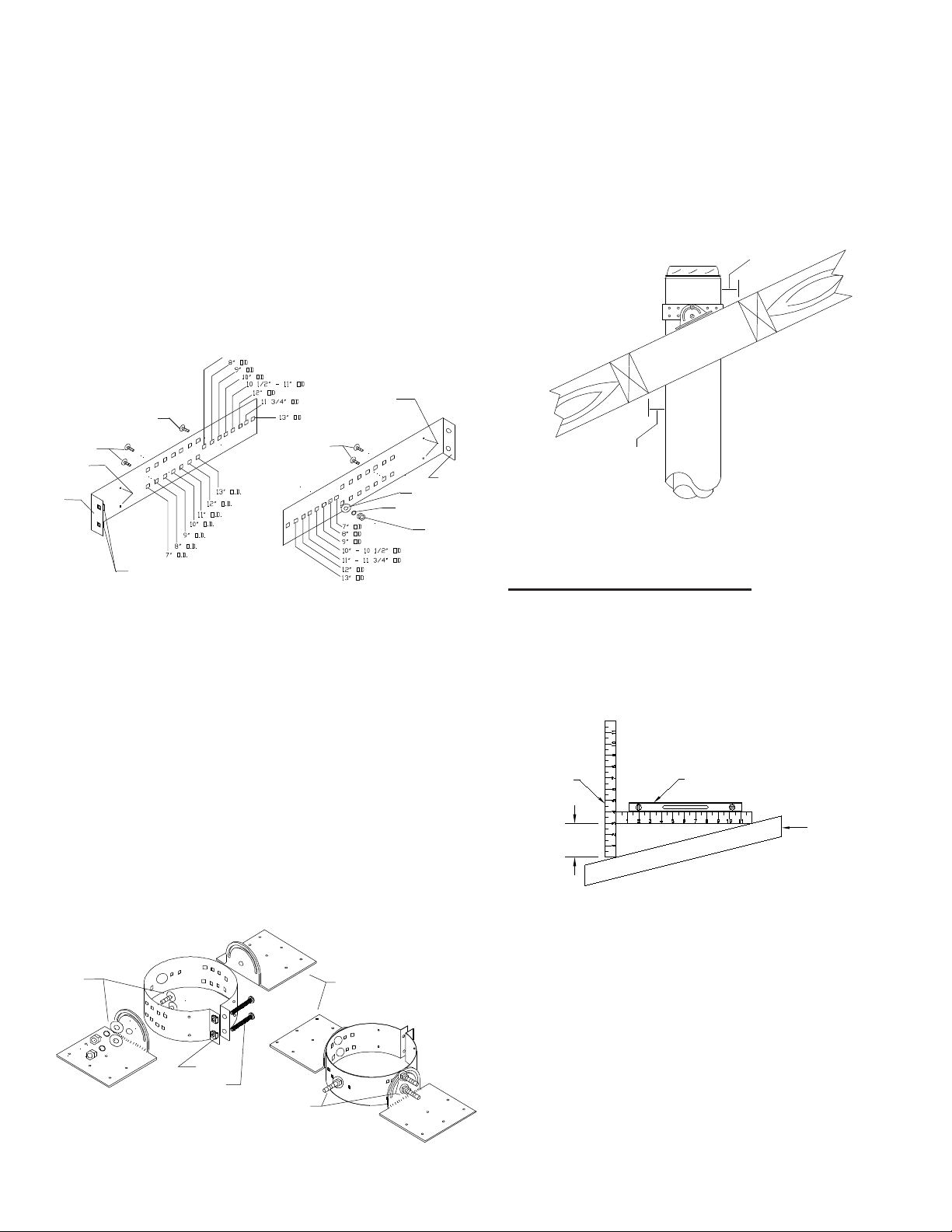
FIGURE27 RoofPitchCalculation
Ensure that you have the proper roof flashing by checking your roof
pitchusingalevelandtworulers(seeFig.22)orbyusingaroofpitch
card.
The FRA-A flashing is for roof pitches from 0/12 to 6/12.
The FRA-P flashing is for roof pitches from 7/12 to 12/12.
ROOF FLASHING: (FRA)
Frame a RECTANGULAR opening to suit the pitch of the roof and
ensure that a 2" (50mm) minimum clearance is maintained to
combustibles.
In new construction, slide a Roof Flashing Assembly suitable to
your roof pitch over the chimney.
On an existing roof, center and install the flashing before extending
thechimneyabovethe roof. Do not nail the flashing to the roof yet.
NOTE: Prepare roof area by removing shingle nails and cutting
roofingmaterialallowing 2" clearance to the chimney. Slide the top
edge(nearesttheroofpeak)ofthe flashingsuitablefortheroofpitch
under the roofing shingles. At least half of the flashing sides
should be UNDER the shingles and the lower end OVER the
shingles to provide a watershed. Trimming off the shingles may
be neccessary around the

14
If the chimney extends 5 feet or more above the roof deck, a
Universal Roof Brace Kit is required (see Figure 35).
ROOF BRACE KIT (URBK)
of the flashing for a better fit. Ensure that the chimney is level and
plumb before nailing flashing to the roof. Nail flashing to the roof
deck(undertheshingles)alongtheupperedgeanddowneachside
with 12 nails with neoprene washers or cover the nails with a
suitable non hardening waterproof caulking . Seal the shingles to
the plate in the same manner. As a precaution, apply a bead of
caulking along all seams of the flashing above the roof as per
Figure 28.
Shingles
Flashing
Nails
RoofFlashingInstallation
Apply a bead of
silicone caulking
along back seamApply a
bead of
silicone
caulking
alongseam
of cone
On steep roofs, it is recommended that an ice deflector or cricket
fabricated from heavy-gauge galvanized steel be installed. The
wedge-shaped deflector is installed against the chimney on the
upper slope. Its function is to split ice and snow as they slide
down the roof, preventing damage to the chimney. This is not a
supplied item. Contact a sheet metal fabrication shop in your
area for your custom ice deflector.
The flashing and storm collar should be painted to match the roof
shingles. This will extend its life and improve the appearance.
The chimney may be painted also with a HEAT RESISTANT
paint. ToimproveadhesiontotheCFSentinelchimney,degrease,
clean, prime before painting. Follow the paint manufacturer's
instructions.
Apply non-hardening high temperature silicone caulking just
above the top of the flashing cone where it meets the chimney
outer casing. Slide the tab end of the storm collar into the slot
end. DONOTBENDTHE TAB OVER YET. Slide the collar down
the chimney until it contacts the flashing and the caulking. Bend
the tab back over the slot for a snug fit. Apply additional caulking
above the storm collar as required.
Continue adding chimney lengths until the proper height is
achieved (See figure 30). Install the Round Top as per the
instructions under the Round Top section.
Figure 28
TheUniversalRoof Brace Kit (URBK)willprovidelateralsupport
to the chimney above the roof line. The URBK is required when
the chimney extends 5 feet (1600mm) or more above the roof
penetration. The URBK contains Telescoping Legs, Support
Band, Roof Angle Brackets and hardware package.
The Universal Roof Brace Kit (URBK) accommodates most
models of chimneys with outer diameters ranging from 7"
through 13".
SingleRowof Holesusedto assemble
SupportBandtoODofthe Chimney
DoubleRowof Holes used
toattachTelescoping Legs
toSupportBand
Figure 29
Support Band Holes Identifier
SupportBandElevator
boltThroughAppropriate
Holesofbothhalves
Figure 30
1/4”Nut
LockWasher
Large
Washer
Form
Tab
Assembly of Universal
Support Band (2 Halves)
CageNuts
Singlerow
selectionholes
usedtoform
SupportBand
A. Measure the outside (OD) diameter of your chimney.
B. From the single row holes (see Figures 29 and 30), select
the hole in each halves that corresponds to the outside
diameter identified with the chimney being installed. Place
the two halves together. Insert an elevator bolt through the
chosen holes (Ex - for an 10” OD chimney, place the elevator
boltthrough theholesidentified for10”OD). The elevatorbolt
should be oriented opposite the direction the formed tabs are
pointed. Secure the center bolt with washers and 1/4”
flanged nut (see Figure 31). NOTE: On smaller diameter
chimney the excess band material can be cut off.
Elevatorboltfor
TelescopingLegs
ThroughAppropriate
Holesofbothhalves
Doublerowsselection
holesusedto
attachTelescopingLegs
NOTE: Upperor Lower
rowcanbe utilized
SecuringHoles
toChimney
(Only1
required)
SingleRowof Holesusedto assemble
SupportBandtoODofthe Chimney
DoubleRowof Holes
usedtoattach
TelescopingLegsto
SupportBand
SecuringHoles
toChimney
(Only1
required)
C. Form the band into a circle and loosely connect tabs using
the supplied 2” bolts into the 2 cage nuts located on1 form
tab.
15
Figure 31 Topview assembly of Support Band -
Elevator Bolt, Washers and Nut
FlangedNut
FlatWasher
SupportBand
Halves
Elevator
Bolt
D. From the double rows of holes (upper or lower row) select the
hole in each halves that corresponds to the OD of the
chimney. Insert 2 elevator bolts (1 per side) through both
holes.
LockWasher
CageNuts
E. Position the Support Band approximately two thirds of the
way up the chimney height (see Figure 35). The preferred
location is next to a joint, immediately above or below a
Locking Band. Secure Support Band by tightening the 2”
bolts.
NOTE: Only one chimney joint should be above a Roof Brace
Kit, the addition of a secondary one may be required.
F. Assemble the telescoping legs by sliding the supplied hose
clamp over larger diameter leg and then inserting smaller
diameter leg into larger diameter leg. Temporarily hold legs
together by tightening the hose clamp over the cut section of
larger diameter leg (see Figure 32). Repeat for the other
telescoping leg assembly.
SmallerDiameter
TelescopingLeg
CutSection of Larger
TelescopingLeg
LargerDiameter
TelescopingLeg
PilotHole for
SecuringScrew
HoseClamp
Figure 32
Assembly of Telescoping
Legs with Hose Clamp
ElevatorBolt
Angledendof
TelescopingLeg
FlatWasher
LockWasher
FlangedNut
ElevatorBolt
Angledendof
Telescoping Leg
FlatWasher
LockWasher
FlangedNut
Figure 33
Assembly of Telescoping
Legs to Support Band
FlangeNut
SmallerDiameter
Telexcoping Leg
RoofShingles
Rafteror framing
structure
1”Bolt
AngleBracket
2”Lag Screws
Figure 34
Securing
Angle Bracket
G. Attach each of the telescoping legs (angled end) to the 2
elevator bolts on the Support Band with supplied washers
and nut (see Figure 33).
H. Attach one end of each telescoping leg assembly to each of
the Angle Brackets using one (1) 1/4-20 X 1” bolt and nut (see
Figure 34).
2”Lag Screws
K. The two telescoping legs should form an angle of about 60°
to give support to the chimney in all directions. The angle of
the telescoping legs should not be more than 45° from
horizontal when fastened to the roof (see Figures 33 & 34).
I. Determine the location of the two Angle Brackets on the roof
structure. Ensure the fasteners are into rafters or framing and
not just roof sheathing. Secure the Angle Brackets to the roof
structure using two (2) 1/4 X 2” lag screws per brackets (see
Figure 28). Seal the roof with a suitable non-hardening
waterproof caulking.
J. Make sure the chimney is level and plumb. Check all required
dimensions and angles, adjust if necessary. For added
security, you may lock in place the telescoping legs by using
1/8” x 1/2” stainless steel self tapping screw (supplied)
through the pilot holes found near the hose clamps (Figure 32).
Secure the Support Band to length of pipe by using four (4) 1/
8” x 1/2” stainless steel self-tapping screws (supplied) through
the2securing holes found closesttothetabson the band (See
Figure 29). Cover screw heads with a suitable caulking.

16
SPARKARRESTER(SA)
Use a spark arrester if you have a shingle roof or live in a forested
area. If the chimney is used for venting a gas appliance, use a
spark arrester to keep birds out.
For 6" to 8" diameters a pre-formed spark Arrester is available.
1.Placethe pre-formedSparkArresterdirectly overthedomeand
skirt of the Round Top (Figure 40).
2. Ensure the flanged end of the Spark Arrester is on top of the
dome and the bottom folded edge overlaps the skirt.
ROUNDTOP(RTS)
1. Place RTS Top over an installed chimney Length so that the
three legs slide down over the outside of the chimney (see Figure
36.
2. Press down evenly on the lower skirt so that the skirt seats
tightly on the upper edge of the chimney Length (see Figure 37).
3. Be sure the RTS Top is level. Place the Cinch Band over the
Length and all legs so that the Cinch Band rests evenly on the
turned-out flanges (see Figure 38).
4. Firmly tighten the Cinch Band with screw and nut provided
(Figure 39). To remove the RTS Top, simply loosen the Cinch
Band and slide RTS Top off the Length.
FIGURE36 FIGURE37
FIGURE38 FIGURE39
RoundTop
SupportBand
LockingBand
AngleBracket
2”Lag screws
10’
MAX
2/3rd
OF HT.
Hose
Clamp
Figure 35
Placement of Universal
Roof Brace Kit
NOTE: Do periodic inspection of all fasteners including the hose
clamps as high winds can cause the chimney system above the
roof to vibrate and in time loosen some of the fasteners.
Spark
Arrester
Ifclogged:
If the Spark Arrester becomes clogged with creosote, it should be
cleaned or replaced. Remove Round Top by removing cinch band.
Lightly tap away (from the outside of the SparkArrester) any creosote
residue. If necessary use a soft bristle brush for assistance. If
Spark Arrester is to be removed from the Round Top, release the
bottom edge of the Spark Arrester from the skirt edge and raise
Spark Arrester from Round Top.
Round Top
Cinch Band
CF
Chimney
Length
FIGURE40

17
“Creosote and Soot - Formation and
Need for Removal”
MAINTENANCE AND CLEANING OF
THE CHIMNEY:
The need for chimney maintenance depends on the kind of
appliance and how it is operated. Gas and oil-burning appliances
need very little, but wood-burning appliances may need a great
deal of chimney maintenance.
How you burn wood in your stove or fireplace directly affects the
formation of creosote. Use more dry kindling and paper first to
warmupthe chimney system to a temperature between 350 to500
F. Burn hot, bright fires and fire each load hot. It is important to
load your appliance properly and to avoid smoldering fires. Fast,
effective start-ups are important, as is the moisture content of the
wood being burned. If your wood is not completely seasoned, split
your wood in smaller pieces instead of larger ones. Ideally, the
moisture content of your firewood should be between 18 to 22%.
A good investment in assisting you in monitoring your system is
a surface thermometer for single wall stove pipe or a probe
thermometer for double wall stove pipe. Ensure only low sulphur
content coal (1% or less) such as anthracite is burned.
When wood is burned slowly, it produces tar and other organic
vapors, which combine with expelled moisture to form creosote.
The creosote vapors condense in the relatively cool chimney flue
of a slow-burning fire. As a result, creosote residue accumulates
on the flue lining. When ignited, this creosote creates a chimney
fire with extremely high temperatures.
With a new installation, the chimney should be inspected
frequently(every2wks)todeterminetherateofcreosoteformation.
When familiar with the appliance and chimney characteristics, the
chimney should be inspected at least once every 2 months during
the heating season to determine if a creosote or soot build-up has
occurred. Check spark arrestor screens at least every 2 to 4
weeks. If the spark arrestor becomes clogged with creosote, it
should be cleaned or replaced.
If creosote or soot has accumulated, it should be removed to
reduce the risk of chimney fire. Depending on the rate of buildup
(aslittleas1/16")andasyoulearnwhatisgoingonin the chimney,
you can adjust your cleaning schedule accordingly. Every
chimneyflueandflue pipe shallbeinspectedannuallyandcleaned
as often as may be necessary to keep the chimney and flue pipe
free from dangerous accumulation of combustibles.
Chimney and flue pipe are particularly susceptible to off-seasn
condensation. The incomplete combustion of wood produces
acids which, when combined with moisture, are corrosive. During
the heating season, corrosion tends not to occur because the heat
in the system evaporates the condensation of any water vapour
that may be formed.
Warm, moist air during the summer months passes slowly
through the heating system. It makes any remaining ash or
creosote moist and soggy. Corrosion of steel occurs where these
deposits remain.
Off-season corrosion can be reduced considerably if the system
is thoroughly cleaned after the last fire of the heating season.
Where coal is burned, the system must be thorougly cleaned
within 48 hours of shutting down the system for the season and all
soot be removed from the chimney system. this should be the
Contact a professional certified chimney sweep for chimney
cleaning services and advice if you have any doubts about your
ability to clean your chimney system or if the task is too large.
If chemical cleaner is used to assist in cleaning your chimney,
make sure it is a product which is non corrosive. Selkirk will
assume no liability for damage resulting from the use of chemical
cleaners. It does not replace the need for a mechanical cleaning.
The optimal method for cleaning a chimney is by a mechanical
brushing of the chimney in conjunction with a complete evaluation
by a certified chimney sweep.
CHIMNEY FIRES AND WHAT TO DO ABOUT THEM
Your CF Sentinel chimney is not intended or designed for use as
a combustion or fire chamber. It is very easy to over fire your
woodburning appliance with kindling, scrap lumber, brush or any
fast burning fuel. This can produce flames and high temperatures
all the way up the chimney,and may cause chimney damage. If
you see your appliance or the stove pipeglowing red, you are
risking chimneydamage, or a fire. The creosote may be burning
inside the chimney.
If you see flames coming out the top, you are either overfiring or
there is a chimney fire. The following materials should not be
burned in your woodburning appliance: pressure treated lumber,
rail road ties, salt water driftwood or plastic. Burning such
materials may lead to severe corrosion of the appliance and the
chimney system.
If the fire in your appliance has gotten out of control, or if you
suspect a chimney fire for any reason, follow these steps:
1. Immediately close all dampers and/or air entrance openings to
your appliance.This includes doors on Franklin type stoves. Block
off fireplace openings.
2. Alert your family to the possible danger.
3. Inspect your appliance and chimney surroundings for possible
fire. If in doubt, alert your Fire Department.
4. Do not continue to use your appliance until it and your chimney
have been thorougly inspected. Overheating can cause metal
parts to expand, buckle and crack. If you are not certain, have a
certified wood technician or certified chimney sweep disassemble
all parts so they can be inspected and replaced.
5. Do not use salt or water on the fire in your appliance. Salt is
corrosive and water will cause a dangerous steam explosion. You
might be able to control the fire by using ashes, sand or baking
soda, since baking soda is an ingredient used for dry chemical fire
extinguishers.
6. After a chimney fire, when it is safe to do so, check internal
locations such as the attic and under the roof and keep watching
for two or three hours. There may be delayed smoldering and
subsequent ignition, even if the fire inside the chimney has been
controlled.
To visually inspect the chimney, remove the Round Top by
loosening the the nut and bolt from the securing band. This will
permit the insertion of a flashlight for inspection and a properly
sized plastic chimney cleaning brush. A metal brush may scratch
the liner and lead to premature corrosion.
The Tee Plug can be removed by turning the lugs to the side. Be
sure to replace the Round Top and the Tee Plug when you are
finished inspecting and cleaning the chimney.
WARNING:
DO NOT USE FUEL MATERIALS CORROSIVE TO
THE CHIMNEY LINER SUCH AS DRIFTWOOD,
PLASTICS, CHEMICALLY TREATED WOOD, ETC.
most careful cleaning the system receives all year. Air inlets
should be closed and sealed if necessary to prevent the constant
flow of air through the system.

18
*CF-36
*CF-24
*CF-18
*CF-12
*CF-9
*CR-IT
*CF-EL15K
*CF-EL30K
*CF-CBSP
*CF-WSP
*CF-WB
*CF-CCB
URSP
*CF-FRA-A
*CF-FRA-P
URBK
*CF-AIS
*CF-JS
*CF-IWT
*CF-RTS
*CF-SPA
*CF-AP
SUSI
REPLACEMENT PARTS LIST
DESCRIPTION PART No.
36" Chimney Length
24" Chimney Length
18" Chimney Length
12" Chimney Length
9" Chimney Length
Insulated Tee/Tee Plug
15oInsulated Elbow Kit
30oInsulated Elbow Kit
Ceiling Support Package
Wall Support Package
Wall Band
Cathedral Ceiling Support
Roof Support Package
Flashing Assembly 0/12-6/12
Flashing Assembly 7/12-12/12
Universal Roof Brace
Attic Insulation Shield
Joist Shield
Insulated Wall Thimble
Round Top
Smoke Pipe Adapter
Anchor Plate
Universal Shielding Insulation
SENTINEL CF
An * asterisk denotes the diameter of chimney (6", 7" or 8").
BURN ONLY SEASONEDFIREWOOD!
Wood burns completely only at very high temperatures with
enoughoxygenpresent. Thefuel,heat, andoxygenhavetomix
together in the same place at the same time. Although all
stages of burning wood actually occur at the same time, it will
burn in 3 stages: boiling off the water, vaporizing wood gases
and burning the charcoal.
Wood burning appliances will burn best with clean, well sea-
soned dry firewood with an ideal moisture content of 18% to
22%. The denser or heavier the wood when dry, the greater its
heat value. Seasoned firewood is essential for an optimum
performance. Seasoned wood will burn hot, emit less smoke
and create less creosote.
Un-seasoned wood when burned, must release water stored
within the wood.This cools the fire, creates creosote and
hampers a complete burn. Be careful of wood advertised as
seasoned. You may want to invest in a moisture meter.
Signs of seasoned firewood are:
- Dark colored; wood darkens with age;
- Cracks in the end grain; radiating from the center of the log like
bicycle spokes;
- Light in weight; which indicates low moisture content - but
hardwood will weigh more than softwood;
- Sound; hit 2 pieces together, wet will have a dull "thud" sound
where as dry will ring like a bat hitting a baseball;
- Easily peeled or broken bark; no green should show under the
bark;
- Burn some; if it hisses, then it is to wet.
The time it takes to season wood varies from 6 to 18 months.
Hardwood dries slower than softwood and some may take well
over a year to dry. To speed-updrying:
- Cut to length;
- Split in a variety of sizes no larger than 6" exposing the wet
interior and increasing the surface area of each piece;
- Stack loosely in a criss cross pattern to get good air circulation;
- Store above ground at least a foot and away from buildings in
a sunny, well ventilated area;
- Cover the top to keep rain and dew off the wood;
- Leave sides open to breezes; for air circulation.
AVOID BURNING "green", "unseasoned" "wet" wood. Heat is
wasted as it must first dry and evaporate the moisture content in
the firewood. As the water evaporates it will form into creosote
which will then condense in the relatively cool firebox and
chimney and will not permit a clean hotburn.
19
H
W
NOTE: It is of utmost importance that this chimney be
installed in accordance with these instructions. Certifica-
tion of the chimney is void if the installation instructions
are not followed. The CF Sentinel chimney requires 2"
(50mm) clearance (air space) to combustible material.
Refer to the following sections in these instructions to
complete your installation to a masonry fireplace:
- Pre-Installation Guidelines
- CF Sentinel Joint Security
- Framing Details
- Attic Insulation Shield
- Firestop Joist Shield
- Elbow Installation
- Roof Support
- Roof Flashing
- Roof Brace Kit
- Round Top
- Smoke Pipe Adaptor
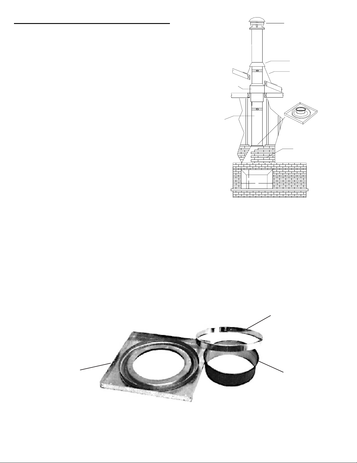
Model CF Sentinel Anchor Plate provides a connection from a
masonry fireplace to a Selkirk Model CF Sentinel chimney. The
following steps describe the installation of this part (component)
and the above mentioned sections of these instructions are to be
followed.
1. Mount four (4) 1/4" diameter bolts, 3" long securely into the
top of the masonry fireplace around the outlet opening. Use the
4 holes on the anchor plate as a template to locate the placement
of these bolts.
2. Apply a bed of mortar approximately 3/4" in depth and 3" in
width completely around the fireplace opening. Make sure the
threadedendsoftheboltsprotrudeaminimumof1"abovethebed
of mortar.
3. While the mortar is still damp, place and level the Anchor Plate
overthe extended studs. Secure using a washer andnut for each
bolt.
4. Check the Anchor Plate for level and allow mortar to set.
5. Place the flue extension (crimped end down) into the opening
of the Anchor Plate. Place a section of chimney onto the Anchor
Plate and secure to the Anchor Plate with a Locking Band and
stainless steel sheet metal screws (see CF Sentinel Joint
Security section of these instructions and Figure 4). Up to 85 feet
of chimney may be stacked on the Anchor Plate.
ANCHOR PLATE - MASONRYFIREPLACE
AllMasonryorSteelShell
ModelSentinelCF
ChimneyLenght-Requires
2"(50mm)clearanceto
Combustibles
AtticInsulationShield
Flashing
Stormcollar
RoundTop
"LISTED" FACTORY-BUILT FIREPLACES
When Selkirk chimney Model CF Sentinel is approved with a
"Listed" factory-built fireplace, the chimney and fireplace are
tested in combination as a complete system and the fireplace
instructions must be followed.
Where required in the "Listed" factory-built fireplace installation
instructions, an Anchor Plate can be used to provide a connection
from a "Listed" factory-built fireplace to the insulated chimney
Model CF Sentinel.
AnchorPlateAssembly
Ensure that you obtain any necessary building permits and that your installation will conform with all federal, provincial,
municipal installations and fire codes for all requirements affecting your installation. Check with your local Building Code
for masonry fireplace requirements.
LockingBand
FlueExtension
Anchorplate(base)
20
2-7/8"
7-3/4"
8-1/4"
11-1/2"
14-3/8"
18-5/8"
20-1/4"
25-1/8"
26-1/8"
28-5/8"
32-3/8"
38-7/8"
AABBAB
13"
20-1/4"
21-1/2"
27"
31-7/8"
39-3/4"
42-1/2"
49-7/8"
50-3/4"
56-1/4"
61"
69-1/4"
3-3/4"
8-3/8"
9-3/8"
11-5/8"
15-1/4"
20-1/4"
22"
26"
26-3/4"
29-3/4"
34-3/8"
39-1/4"
14"
21-1/4"
22-3/4"
27-1/2"
33"
40-3/8"
42-1/2"
50-3/8"
52"
56-1/2"
61-5/8"
70-7/8"
3-3/4"
7-3/4"
7-5/8"
11-3/8"
14-1/2"
18"
21"
24-1/4"
24-3/4"
28-3/8"
32-1/4"
37-1/4"
14-1/4"
22-1/8"
23-1/2"
28-3/4"
34-1/4"
42-1/4"
44-1/4"
52-3/8"
53-7/8"
58-7/8"
64"
72-1/2"
1"
3-1/4"
4"
5-1/2"
7-1/8"
9-5/8"
10-3/8"
12-1/2"
13-1/4"
15-7/8"
22-1/4"
23-1/2"
AA
BBAB
11"
19-1/2"
20-7/8"
26-1/2"
32"
40-5/8"
43-7/8"
52-1/4"
54"
59"
64-7/8"
75-1/8"
1-1/4"
4"
4-1/4"
5-5/8"
7-1/8"
10-1/4"
10-3/4"
13"
13-1/2"
15-5/8"
17-7/8"
20-1/2"
11"
19-1/2"
21-1/8"
26-3/4"
32-5/8"
40-7/8"
43-7/8"
52-1/8"
53-5/8"
59"
65-1/8"
75-3/8"
1-3/4"
4-1/8"
4-3/8"
6"
8"
10"
11-1/8"
13-1/8"
14-1/2"
15-1/8"
17-3/8"
21-1/4"
10-3/4"
19-1/4"
20-7/8"
26-3/4"
32-3/4"
41-1/8"
44"
52-1/8"
53-3/4"
59-3/4"
65-5/8"
75-1/2"
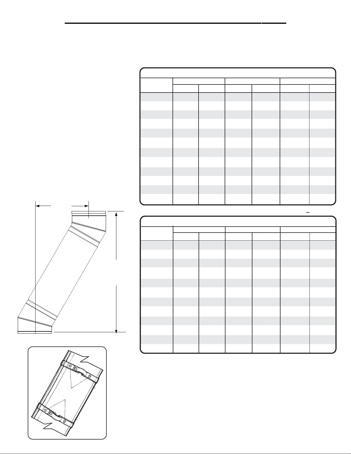
CHART 1 - OFFSET CHIMNEY INSTALLATION
When the chimney path cannot be perfectly straight, the need to install a chimney offset must be used when it becomes necessary
to offset the chimney in order to clear a joist or an obstacle. The two (2) charts below will assist you in selecting the proper combination
of elbow angle and chimney length(s) that will provide the necessary degree of offset within an available height.
1. Select the column with the proper chimney
diameter of your system.
2. Determine the distance of the offset required
by dropping a plumb bob for an accurate mea-
surement. The offset is measured at the chim-
ney centre line as per the "A" measurement in
the diagram.
3. On the chart, find the predetermined distance
(under the "A" column) required for the 15o
elbow. For greater offset, use the 30ooffset
chart.
4. After finding the offset, look under column "B"
to find the specified height and appropiate "chim-
ney lengths" required in the left column.
NOTE:
•Sentinel CF chimney is limited to offsets not exceeding 30 degrees. Combining offsets for greater
angle is not permitted.
•Two pairs of (four) 15oor 30oelbows may be used per interior installation.
•Locking bands must be used at each joints. For added security on multiples lengths forming
an offset, fasten the joints using two (2) #6 x 1/2" stainless steel sheet metal screws through
the pre-punched holes in the locking bands (see diagram on the left).
•Never install an elbow in a joist area. Chimney sections must pass vertically through framed
joist areas.
•Elbow support will support 30 feet of chimney and the maximum length of chimney allowed
between elbows is 6 feet.
StainlessSteel
SheetMetal
Screws
"A"
Offset
"B"
Height
30oOFFSET CHART
Chimney 7" Diameter6"Diameter 8" Diameter
Lengths
none
9"
12"
18"
24"
9" + 24"
36"
9" + 36"
12" + 36"
18" + 36"
24" + 36"
12"+24"+36"
All measurements in these charts are in inches. Construction tolerances + one inch.
15o OFFSET CHART
Lengths
Chimney 7" Diameter6"Diameter 8" Diameter
none
9"
12"
18"
24"
9" + 24"
36"
9" + 36"
12" + 36"
18" + 36"
24" + 36"
12"+24"+36"
Table of contents
Other Selkirk Ventilation Hood manuals


Popular Ventilation Hood manuals by other brands


Sirius Range Hoods
Sirius Range Hoods SUT900 installation instructions

INOXPAN
INOXPAN Pando User and installation manual

Franke
Franke FPJ 615 V BK A user manual

Pando
Pando P-960 installation manual

Electrolux
Electrolux LFP316AS user manual

BKI
BKI Ventless Hood System FH-28 Installation and operation manual

Haier
Haier HPH90ILX1 Quick reference guide

Bosch
Bosch DAH9465UC installation instructions

BOMANN
BOMANN DU 623.3 instruction manual

Miele
Miele DA 3160 Operating and installation instructions

Küppersbusch
Küppersbusch KD 9450 Instruction booklet

Whirlpool
Whirlpool 99043751B Installation Instructions and Use & Care Guide