SELO SP 250 User manual
USER’S MANUAL
SCHNITZEL PRESS
SP 250 Rev 05/ SP 400 Rev 05
SELO
ORDER NUMBER SELO B.V.
Postbus 357
NL-7570 AJ Oldenzaal, The Netherlands
Tel: (31) 541 – 58 20 00
Fax: (31) 541 – 52 15 95
Website www.selo.com
Visitor’s address:
Eektestraat 1
DB 05045 7575 AP Oldenzaal, The Netherlands
Version 1.3 Date: January 2005

SCHNITZEL PRESS
User’s manual
Version 1.3
01-2005 Type : SP250 Rev 05 / SP400 Rev 05 Selo
Selo B.V. 2
Copyright Selo B.V., The Netherlands, 2006
All rights reserved.
All technical and technological information included in this manual, as well as any drawings and
technical descriptions made available by us, are the property of Selo B.V. and may not be copied,
reproduced or in any way made available to third parties without our prior express written permission.
If there are data cited in this manual that deviate from that stated in one or more written agreement(s)
concluded with Selo B.V., then that written in this (these) agreement(s) is of overriding importance.
In addition, Selo B.V. reserves the right to revise this publication and implement modifications to the
content over certain periods of time without the obligation to give advance notice of such a revision or
modification.
In spite of all the care taken in the composition of this user's manual, Selo B.V. can accept no liability
for any damage, which may be the result of any error, which may appear in this user’s manual. No
rights can be derived from the text of this user’s manual. Should you encounter any imperfection in the
text, we would be very appreciative if you were to communicate this to us. Suggestions on how to
improve this user’s manual are also more than welcome.
SCHNITZEL PRESS
User’s manual
Version 1.3
01-2005 Type : SP250 Rev 05 / SP400 Rev 05 Selo
Selo B.V. 3
Foreword
I How to use this manual
This manual is designed to help you use and maintain the Schnitzel press in a safe way.
The manual has been compiled for users of the FMS Mixer.
The manual is divided into eight chapters and also includes tables, drawings, diagrams, explanatory
notes and a number of appendices, to give you easy access to the information you are looking for.
Foreword
Contains information on how to use this manual.
Contents
Contains a numbered list of all of the chapters and sections of this manual.
Chapter 1 Introduction
Contains general information regarding the Schnitzel press, describes how the system works and sets
out the requirements that apply to the conditions of use and the qualification requirements that apply
to the personnel responsible for operating the machine.
Chapter 2 Safety
Describes the most significant safety risks, the safety devices installed in the machine, the safety
precautions that need to be observed and the meaning of the symbols displayed on the Schnitzel
press.
Chapter 3 Transport and storage
Chapter 4 Installation and connecting up the machine
Describes how to install and connect up the Schnitzel press and the procedures to be followed in
programming the settings of the machine.
Chapter 5 Operating
Explains how to operate the machine and how to solve any problems that may be encountered.
Chapter 6 Cleaning and maintenance
Appendices
Contain additional information and forms and checklists for inspection and control.
II Notation of important points
Certain parts of the text of this manual call for special attention. These parts of the text are indicated as
follows:
Tip : Gives the user suggestions and advice on how certain tasks can be carried
out more easily or more efficiently.
Please note! A comment that provides important additional information, alerting the user
to possible problems.
Warning : Important points to be observed. In failing to observe these warnings the
user may sustain (serious) injury or cause serious damage to the product.

SCHNITZEL PRESS
User’s manual
Version 1.3
01-2005 Type : SP250 Rev 05 / SP400 Rev 05 Selo
Selo B.V. 4
Table of contents
CHAPTER 1 INTRODUCTION ........................................................................................5
1.1 PRODUCT DESCRIPTION..................................................................................................5
1.2 DESCRIPTION OF MAIN COMPONENTS..............................................................................6
1.3 PURPOSE.......................................................................................................................6
1.4 OPERATING CONDITIONS ................................................................................................6
1.5 OPERATOR REQUIREMENTS............................................................................................7
1.6 CONTROLS.....................................................................................................................7
CHAPTER 2 SAFETY....................................................................................................10
2.1 INTRODUCTION.............................................................................................................10
2.2 SAFETY AND HEALTH RISKS..........................................................................................10
2.3 SAFETY DEVICES..........................................................................................................10
2.4 SAFETY MEASURES TO BE TAKEN INTO ACCOUNT..........................................................10
2.5 SAFETY MEASURES DURING OPERATION .......................................................................11
CHAPTER 3 TRANSPORT AND STORAGE................................................................12
3.1 TRANSPORT.................................................................................................................12
3.2 STORAGE.....................................................................................................................12
CHAPTER 4 INSTALLATION AND START-UP ...........................................................13
4.1 INTRODUCTION.............................................................................................................13
4.2 INSTALLATION..............................................................................................................13
CHAPTER 5 OPERATION ............................................................................................16
5.1 INTRODUCTION.............................................................................................................16
5.2 OPERATION..................................................................................................................16
5.3 SETTINGS ....................................................................................................................16
5.4 OPERATING THE SCHNITZEL PRESS...............................................................................16
5.5 OPERATION FAILURES..................................................................................................17
CHAPTER 6 CLEANING AND MAINTENANCE...........................................................19
6.1 INTRODUCTION.............................................................................................................19
6.2 CLEANING....................................................................................................................19
6.3 INSPECTION .................................................................................................................20

SCHNITZEL PRESS
User’s manual
Version 1.3
01-2005 Type : SP250 Rev 05 / SP400 Rev 05 Selo
Selo B.V. 5
CHAPTER 1 INTRODUCTION
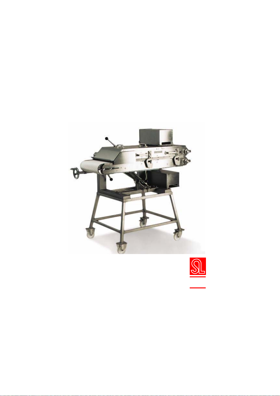
The Selo Schnitzel Press is a machine for pressing veal, beef, pork or poultry.
Product examples: schnitzels, meat rolls, braising steak, chicken fillet, turkey, meat.
The pressing action is established by a combination of two specially profiled belts (rep 218/275), one
on top of the other.
The belts are driven independently of each other. The machine is equipped with a continuous
thickness adjuster.
The pieces of meat should be placed manually onto the feed section of the machine. The feed side is
protected by a protective cover with proximity switch.
The machine is operated by means of switches on the control panel.
The machine is made of stainless steel for as much as is possible. The belts are coated with white
“Nomex 65” PVC. (Meet the FDA requirements.)
1.1 Product description
A. Schnitzel press
B. rolling undercarriage
C. switch box with control
panel
Figure 0.1 Overview of main components
B
C
A
SCHNITZEL PRESS
User’s manual
Version 1.3
01-2005 Type : SP250 Rev 05 / SP400 Rev 05 Selo
Selo B.V. 6
1.2 Description of main components
•SWITCH BOX of the schnitzel press
The switch box is fitted with equipment for switching the motors. This equipment consists of
the following parts:
•Contactors;
•Transformer;
•Thermal safety device control current 2A;
•Thermal motor safety switch;
•Phase-sequence monitoring;
•Three push buttons for starting/stopping/reversing the belt
•Warning light
•Three contact plugs
The switch box’s stop button also serves as an emergency stop.
Electrical installation
The schnitzel press’s switch box is fitted with two circuits.
1. Main electrical circuit 400V (see appendix C).
2. Control current circuit 24V (see appendix C).
Electrical circuit
The main electrical circuit and control current circuit are illustrated in appendix C.
Transport belts
Description: “Nonex 65” PVC coating.
Warning:
Please note the arrow indicating the correct feed direction of
the belts when (re)assembling them (this arrow is printed on
the inside of the belt(s)).
Please follow the instructions in Chapter 6 “Cleaning and
Maintenance” when assembling a new belt.
Motor reductor 400 V
For type SP – 250 Rev 05: Electromotor 27 rpm, 0.15 kW, 3 phase, 50 Hz, 0.6 A, see type plate.
For type SP – 400 Rev 05: Electromotor 25 rpm, 0.37 kW, 3 phase, 50 Hz, 1.24 A, see type plate.
Switches
Mechanically forced type.
All the technical specifications of the schnitzel press are included in appendix A of this user’s manual.
Contactor
Mechanically forced type.
All the technical specifications of the schnitzel press are included in appendix A of this user’s manual.
1.3 Purpose
The schnitzel press may only be used for pressing veal, beef, pork or poultry.
Product examples: schnitzels, meat rolls, braising steak, chicken fillet, turkey, meat.
The schnitzel press should not be used for other purposes.
1.4 Operating conditions
The schnitzel press may only be used under the following operating conditions.
•The schnitzel press should be placed on a solid, level surface.
•The schnitzel press should be stable and level.
•Before operating the schnitzel press, the brake of the swivelling wheels (if the undercarriage is
supplied) should be secured.
SCHNITZEL PRESS
User’s manual
Version 1.3
01-2005 Type : SP250 Rev 05 / SP400 Rev 05 Selo
Selo B.V. 7
1.5 Operator requirements
The schnitzel press may only be used by people that have been instructed and are familiar with its
operation.
Warning: Selo B.V. recommends the use of safety shoes with antiskid soles
for all actions performed to the schnitzel press.
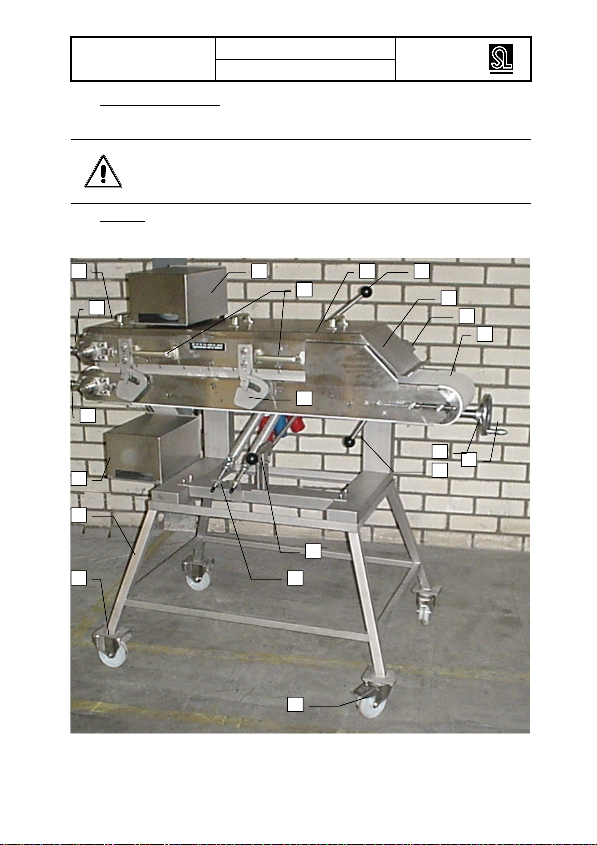
1.6 Controls
The schnitzel press is controlled using push buttons installed on the switch box. The control panel and
controls are illustrated in figure 1.2; the functions relating to the buttons are outlined in table 1.1.
3
17
2 12
11 20
10
15
14
13
16
1
8
7
6
5
4
19
18
9
17

SCHNITZEL PRESS
User’s manual
Version 1.3
01-2005 Type : SP250 Rev 05 / SP400 Rev 05 Selo
Selo B.V. 8
Figure 1.2 Controls
Item Description Item Description
1 Removable protective cover 16 Locking/unlocking upper belt/ thickness
adjustment cam
2 Removable protective cover 17 Handle for tipping upper belt
3 Protective motor cover 18 Upper belt scraper
4 Protective motor cover 19 Feed belt scraper
5 Undercarriage 20 Switch box
6 Frame wheel 21 24V socket, feed valve safety
7 Swivelling wheel 22 400V socket, power supply for drive motors
8 Upper belt tipping fastener 23 Warning light “Machine is live”
9 Unlocking handle for upper belt tipping
position 24 Start button
10 Hand wheel for upper belt thickness
adjustment / tipping position 25 Stop button
11 Lower belt tightening lever 26 Reverse key switch
12 Upper belt tightening lever
13 Safety feed valve
14 Safety contactor
15 Feed belt
22 22 21
20
26
252423

SCHNITZEL PRESS
User’s manual
Version 1.3
01-2005 Type : SP250 Rev 05 / SP400 Rev 05 Selo
Selo B.V. 9
Table 1.1 Control functions
Control Function
Push button ‘Start’ The schnitzel press is activated, the transport belts are starting.
Push button ‘Stop’ The schnitzel press stops immediately.
Push button ‘Reverse’ The ‘Reverse’ switch should be used in combination with the ‘start’
button so as to move the belts into the opposite direction. (This
operation is only possible when the start button and the reverse
button are operated simultaneously.) Function tip: the belts reverse
2 cm per button push
Safety contactor The schnitzel press’s power supply is interrupted. The machine
stops as soon as the safety feed valve is opened.
Attention: When the safety feed valve of the schnitzel press is opened, the
machine stops. You should push the 'Start' button again so as to
complete the operation; the machine will start again.
Machine type plate

SCHNITZEL PRESS
User’s manual
Version 1.3
01-2005 Type : SP250 Rev 05 / SP400 Rev 05 Selo
Selo B.V. 10
CHAPTER 2 SAFETY
2.1 Introduction
This chapter outlines all safety aspects. It is of the utmost importance that everyone operating the
schnitzel press is informed on the contents of this chapter.
Tip: If the safety aspects are not clear to you, please ask the
manufacturer for more information.
The main safety and health risks related to the schnitzel press are outlined in paragraph 2.2.
Paragraph 2.3 then describes the safety devices that have been installed on the schnitzel press.
Furthermore, paragraph 2.4 states the safety measure that should be considered by the operator of
the schnitzel press.
2.2 Safety and health risks
The following safety and health risks should be taken into account for the schnitzel press (the numbers
refer to the paragraphs in this manual explaining the mentioned risks):
Decreased stability of the machine caused by incorrect installation............................................3.1, 3.2
Direct or indirect electrical contact ...........................................................................2.3.2, 2.3.3, 4.2, 6.2
Correct or incorrect securing of the wheel blocking ............................................................................3.2
Malfunction of one of the switches......................................................................................................5.5
Damage to the cables or connectors................................................................................................6.3.1
Detaching of the protective covers and/or screen covers from the schnitzel press (during transport)3.2
Reversion of the top part caused by an incorrect action / installation.................................................6.2
Hands getting stuck between feed valve and transport belt................................................................2.4
Chance of blisters when touching the belt at the scrapers (conveyance side)...................................2.4
The designers of the schnitzel press were aiming at reducing these risks as much as possible; the
safety devices for this purpose are listed in paragraph 2.3. In order to protect himself against the
remaining risks, the operator of the schnitzel press should take the required safety measure into
account. These are listed in paragraph 2.4.
2.3 Safety devices
The following safety devices have been installed so as to make the operation of the schnitzel press as
safe as possible.
The schnitzel press is fitted with a stop button and safety contactor for stopping the machine
immediately in case of emergency.
The electromotors are thermally protected, preventing overheating.
A safety valve with safety contactor is mounted above the feed belt. The schnitzel press stops
immediately when the safety valve is pushed upwards.
The safety contactor and 'stop' button can also be used together as an emergency stop.
2.4 Safety measures to be taken into account
A number of safety measures should be taken into account in view of a safe operation of the schnitzel
press.
SCHNITZEL PRESS
User’s manual
Version 1.3
01-2005 Type : SP250 Rev 05 / SP400 Rev 05 Selo
Selo B.V. 11
Personal protection
Selo B.V. advises the use of safety shoes and antiskid soles while operating the schnitzel press.
Safety precautions:
Make sure that the operation, small maintenance jobs and actions for installing, constructing or
moving the schnitzel press are only performed by qualified personnel, i.e. personnel that is
competent and familiar with the contents of this manual.
Make sure that the schnitzel press is installed correctly and in a stable way.
Check whether the voltage source complies with the local regulations.
The connection and the circuit in the schnitzel press are performed by a safety earth. Make sure
you have the correct earth connection.
Use earthed leads and extension leads having a diameter that is large enough and a voltage
source equipped with an earth leakage circuit breaker.
Make sure that the wall socket and any connections between the extension leads are well
protected against humidity. Do not pull the plug out of the wall socket or extension lead by the lead.
2.5 Safety measures during operation
Warning: Never operate the schnitzel press when the switch box and/or
connections are wet.
Attention! : Remove the reverse key from the schnitzel press and keep it in a
safe place.
Warning: Be careful when placing meat on the feed belt. Make sure that your
hands do not get stuck between the feed belt and the feed valve.
Warning: Watch out for the scrapers at the conveyance side on the feed belt
when handling pressed meat. Make sure that your hands do not
touch the belt and/or scrapers.
Keep the space around the schnitzel press free of materials and other obstacles.
Do not put any loose tools or objects on the schnitzel press or switch box. These can end up or fall
between moving parts.
If you leave the schnitzel press unattended, the power supply should be disconnected from the
switch box.
Safety measures during inspection, cleaning and maintenance
Make sure that maintenance and repair works should only be performed by expert and skilled
people. This type of work may only be performed when the schnitzel press is switched off.
Make sure that the power is disconnected when opening the switch box and during maintenance.
Measures for keeping the schnitzel press in good condition
Make sure that the schnitzel press is always in good condition.
When the schnitzel press is used at regular intervals, it should be checked at least once a year.
Pay special attention to the electric cables, which may not be damaged, and the belts, which
should be in good condition, and the correct functioning of the operation.

SCHNITZEL PRESS
User’s manual
Version 1.3
01-2005 Type : SP250 Rev 05 / SP400 Rev 05 Selo
Selo B.V. 12
CHAPTER 3 TRANSPORT AND STORAGE
3.1 Transport
When the schnitzel press is transported the rolling undercarriage and the schnitzel press must be
transported separately. Protective and security covers must be attached to the machine.
Transport in the production area
In the production area, the schnitzel press can be transported on the rolling undercarriage that is
especially for that purpose.
3.2 Storage
Perform the following actions before storing the schnitzel press:
Before storing the schnitzel press, perform a general check-up. Check all the vital parts:
-Safety contactor;
-Switches;
-Switch box;
-Wheels.
If necessary, replace the damaged parts.
Before storage, the schnitzel press must be cleaned.
Place the schnitzel press on a level and stable surface.
Secure the wheels.
SCHNITZEL PRESS
User’s manual
Version 1.3
01-2005 Type : SP250 Rev 05 / SP400 Rev 05 Selo
Selo B.V. 13
CHAPTER 4 INSTALLATION AND START-UP
4.1 Introduction
This chapter describes how the schnitzel press should be prepared for operation. Paragraph 4.2
discusses the basic operations for the installation. The required settings are described in paragraph
4.3. In conclusion, paragraph 4.4 indicates which checks must be performed before the schnitzel press
may be operated.
4.2 Installation
Warning:
Make sure that the following regulations are met before connecting
the electric power:
- The voltage source meets the local regulations;
- You have a correct earth connection;
- The used extension cords are earthed and have a sufficient
diameter;
- The voltage source is provided with an earth leakage circuit
breaker;
- The wall socket and any connections between the extension
cords are well protected against humidity.
1. Place the schnitzel press on a level and stable surface which is free of materials.
2. Secure the wheels of the rolling undercarriage (if the undercarriage has been supplied).
3. Set the thickness adjustment of the machine.
A set of adjusting tools has been supplied in the packing of the switch box.
This set contains two bars with an end piece of 12 mm and two blocks of 8 mm thick.
Warning:
When mounting a new switch box or a switch box of another
schnitzel press, the rotation direction must first be checked. A
phase-sequence control is installed in the new switch boxes. So
before using the schnitzel press, check the rotation direction of the
belts!

SCHNITZEL PRESS
User’s manual
Version 1.3
01-2005 Type : SP250 Rev 05 / SP400 Rev 05 Selo
Selo B.V. 14
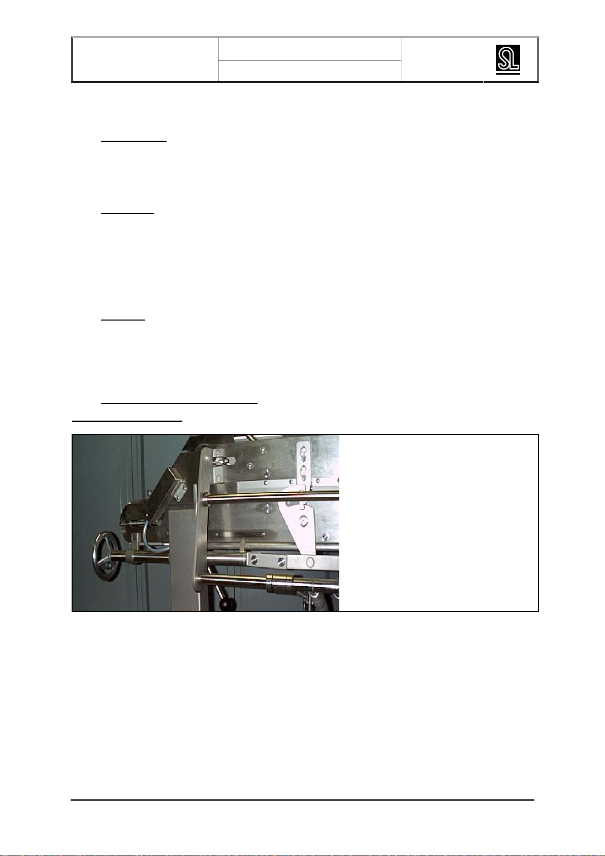
•Turn the hand wheel to create the
required distance between the upper
and lower belt.
•Place the calibres as shown.
•(Place the 12 mm calibres between
the first two small rollers)
•Place the 8 mm calibres between the
two large rollers on the conveyance
side.
•Lower the upper belt by turning the
height adjusting hand wheel. Stop as
soon as the rollers have contact with
the first calibres.
•Loosen the fixing screws of the
upper belt so the top part touches
the four calibres.
•Turn the thickness adjustment hand
wheel to 13.5.
•Secure the fixing screws.
•Turn the hand wheel to the right (up)
and remove the calibres.
13,513,5

SCHNITZEL PRESS
User’s manual
Version 1.3
01-2005 Type : SP250 Rev 05 / SP400 Rev 05 Selo
Selo B.V. 15
4. Place the switch box on top of
the schnitzel press (between the
two handles of the safety lid of
the upper belt).
5. Connect the plugs of the
schnitzel press to the switch box
(the two red plugs can be
exchanged).
6. If necessary, adjust the
scrapers of the upper and lower
belt.
The schnitzel press is now ready
for use.
See chapter 5 ‘operation’ for more
information on the operation of the
schnitzel press.
SCHNITZEL PRESS
User’s manual
Version 1.3
01-2005 Type : SP250 Rev 05 / SP400 Rev 05 Selo
Selo B.V. 16
CHAPTER 5 OPERATION
5.1 Introduction
The actual operation of the schnitzel press is very easy. It is, however, very important to take all the
safety regulations into account when working with the schnitzel press. The first part of this chapter is
dedicated to the operational actions that must be performed on the schnitzel press, followed by a
discussion of the possible failures, causes thereof and solutions for repairing the failures.
5.2 Operation
The pressing action is established by a combination of two specially profiled belts, one on top of the
other.
The belts are driven independently of each other. The machine is equipped with a continuous
thickness adjuster.
The pieces of meat should be placed manually onto the feed section of the machine. The feed side is
protected by a protective cover with safety contactor.
The machine is operated by means of switches on the control panel.
5.3 Settings
When the schnitzel press is used for the first time, the instructions of chapter 4 'Installation and start-
up' should be followed strictly.
When all the plugs of the switch box are connected, connect the plug of the switch box to the wall
socket. The light of the switch box will then be switched on. (The switch box is live, the schnitzel press
is now ready for use.)
5.4 Operating the schnitzel press
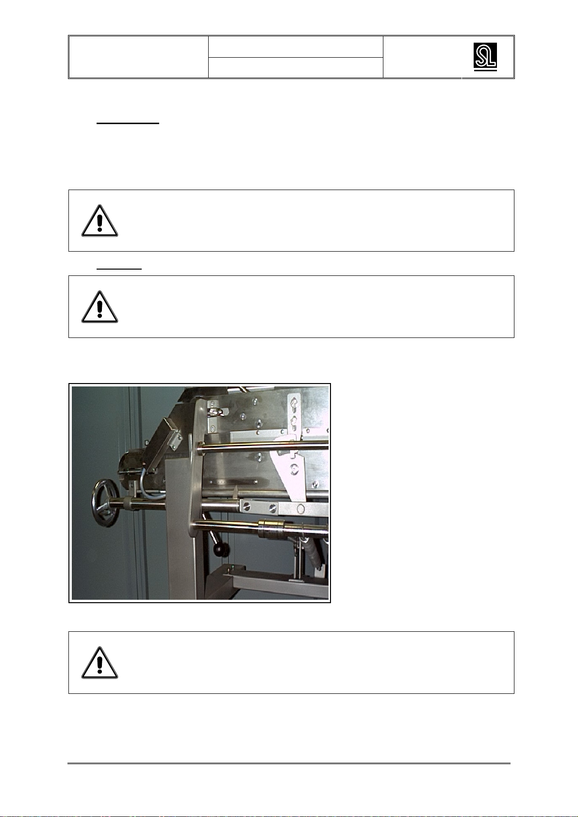
Thickness adjustment:
When the hand wheel is turned to the
right, the distance between the two belts
increases.
(in the end position, the upper part can
be tilted, the thickness indication is
approximately 15)
Before operating the schnitzel press, make sure that the area around the schnitzel press is free from
obstacles.
The schnitzel press is operated with push buttons that are mounted on the switch box. If the ‘Start’
button is pressed, the belts will start running. If the ‘Stop button is pressed, the belts will stop. If the
‘reverse’ switch is operated with the matching key and is kept on position [I] while you press the ‘start’
button, the belts will run in the opposite direction (2cm each time). If the stop button is pressed, the
schnitzel press stops immediately.

SCHNITZEL PRESS
User’s manual
Version 1.3
01-2005 Type : SP250 Rev 05 / SP400 Rev 05 Selo
Selo B.V. 17
5.5 Operation failures
Practice has shown that approximately 95% of the failures are not in the switch box. So first of all look
for the failures outside of the switch box and check the fuses and automatic parts in the building
terminal box, the voltage of the main power circuit and the thermal magnetic motor protection switch in
the switch box. In any case, check the fuses, the end switches and the wiring outside of the switch box.
In table 5.1 you can find an overview of failures, matching causes and actions to repair the failures.

SCHNITZEL PRESS
User’s manual
Version 1.3
01-2005 Type : SP250 Rev 05 / SP400 Rev 05 Selo
Selo B.V. 18
Table 5.1 List of failures
Observation Possible cause Action
Machine does not start
up The plug of the supply cable is
not plugged in check the extension cord, plugs, contactors
and motors. After that, switch the thermal
motor protection switch back on manually.
Plug(s) of motor cable of
upper and lower belt not
plugged in on the switch box.
Repair.
Safety feed valve 227 is up
which means that the safety
contactor is interrupting the
supply
Close valve.
Plug of the cable contactor is
not plugged in on the switch
box.
Repair.
Machine does not start
up and the light of the
switch box is off.
Phases of the supply cable
have been connected
incorrectly
Contact Selo Service for correctly wiring
the switch box
Motor is not running, is
humming or is becoming
exceptionally hot.
Error in the main electrical
circuit. ATTENTION! Make sure that the
machine is not live when you are
performing the measurements.
Use a volt meter to check the main
electrical circuit including the fuses in the
switch box of the structure, the extension
cord, the plugs in the thermal motor
protection switch in the switch box of the
schnitzel press or until the connection to
the motor. Check if the wiring is fixed well.
motor is not running, is
humming or is becoming
exceptionally hot. A
cracking sound comes
from the reductor when
switching the motor on
and off.
the gear wheels in the
reductor are broken. Contact Selo Service B.V.
motor is not running, is
humming or is becoming
exceptionally hot. A
stinking sickly smell
comes from the motor.
the motor is entirely or partly
burnt. Contact Selo Service B.V.
motor becomes
extremely hot. One or two windings of the
motor have stopped working
properly. The motor is burnt
for approx. 40%. Also see:
stinking smell comes from
motor.
Contact Selo Service B.V.
thermal safety 2A is
switched off Short circuit in the control
current circuit. ATTENTION! Make sure that the
machine is not live when you are
performing the measurements.
Check if the wiring is fixed well. Check the
transformer and the coils of the contactors.
If the schnitzel press shows a failure which is not included in table 5.1 or which you cannot repair by
means of this table, please contact Selo Service B.V.
SCHNITZEL PRESS
User’s manual
Version 1.3
01-2005 Type : SP250 Rev 05 / SP400 Rev 05 Selo
Selo B.V. 19
CHAPTER 6 CLEANING AND MAINTENANCE
6.1 Introduction
The schnitzel press is designed and constructed in such a way that maintenance can be reduced to a
minimum. There are no lubrication points on the schnitzel press and all the bearings in the drive and
motor unit are self-lubricating.
However, make sure that no hard materials, dust or dirt gets between the turning parts; keep the
schnitzel press clean and tidy.
Warning: Maintenance and repair works must be performed by expert and
competent people, preferably qualified engineers of the
manufacturer or from your own technical service.
6.2 Cleaning
Warning: Switch off the main power supply.
1. Remove the plugs from the switch box.
2. Disconnect the control panel and put it in a dry place.
3. The height of the adjustment cams
can be adjusted with the hand wheel
on the feed side.
4. When the wire pot with indicator
reaches the front position, the top
part is free of the height adjustment
brackets.
5. You can tip over the upper part of the machine using the two handles located on the front of the
schnitzel press.
Warning:
When tipping over the upper belt, you should use the two handles
(figure 1.2 rep 17), lift the upper part until the bolting handle locks.
By lifting the upper part slightly and holding the lever up, you can
slowly lower the upper part.
6. Both conveyers will slacken by pulling the tightening levers.
7. Disassemble the scrapers and remove the belts.
SCHNITZEL PRESS
User’s manual
Version 1.3
01-2005 Type : SP250 Rev 05 / SP400 Rev 05 Selo
Selo B.V. 20
Warning: When the machine is cleaned with a high-pressure cleaner, the
plugs and motors may not be sprayed. Make sure that the
removable protective motor covers are present.
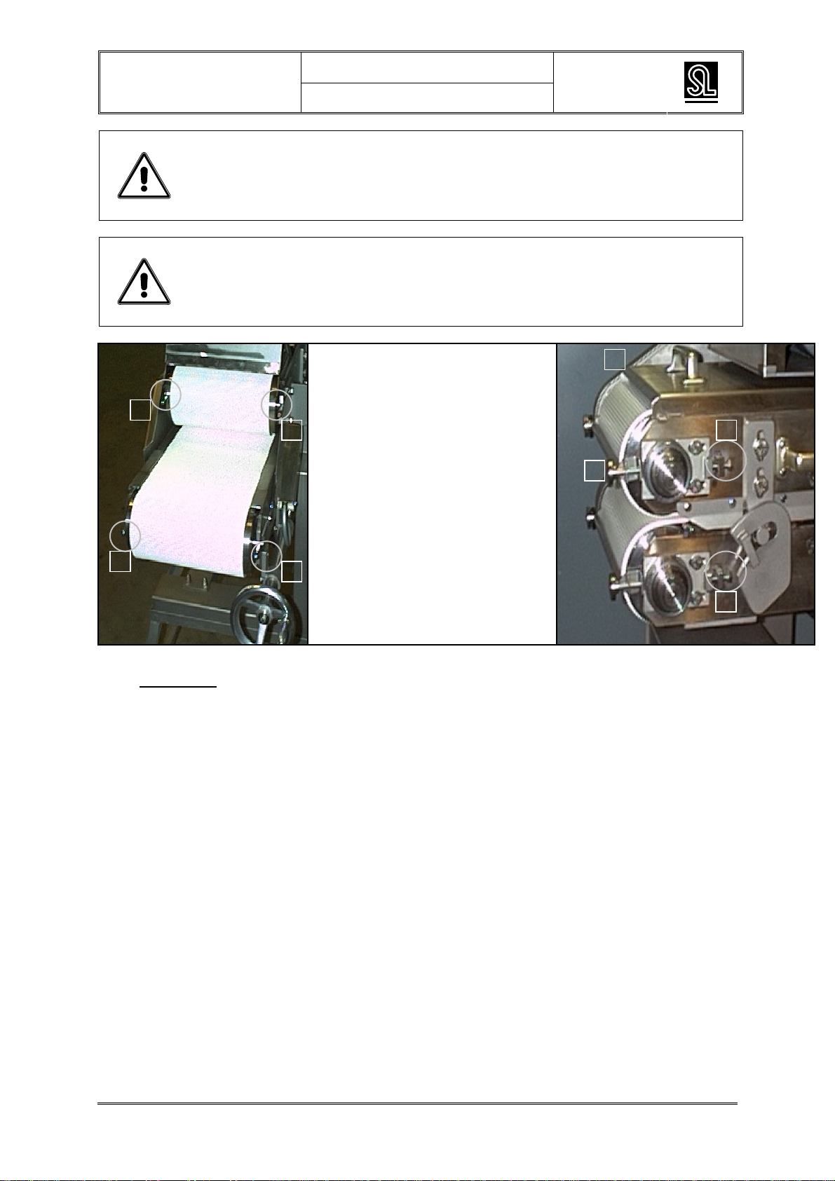
Warning: When mounting a new belt, the tension and position of the scraper
must be adjusted and the belt must run straight. That can be done
with the adjustment bolts on the feed and conveyance side.
Adjustment of the tension and
making sure that the upper belt is
running straight on the feed and
conveyance side
A1, A2: Adjusting screws on the feed
side, upper belt
B1, B2: Adjusting screws on
the feed side, lower belt
Conveyance side: Attention! First
unscrew the fixing bolts. *
C1, C2: Adjusting screws on the
conveyance side, upper belt
D1, D2: Adjusting screws on the
conveyance side, lower belt
6.3 Inspection
Monthly
During the weekly inspection, pay extra attention to the following points:
The electrical insulation;
Correct functioning of the switches;
Correct functioning of the control tools.
A1
A2
B1 B2
C1
C2
D1
D2
*
*
*
*
This manual suits for next models
1
Table of contents
Popular Commercial Food Equipment manuals by other brands


Diamond
Diamond AL1TB/H2-R2 Installation, Operating and Maintenance Instruction

Salva
Salva IVERPAN FC-18 User instructions

Allure
Allure Melanger JR6t Operator's manual

saro
saro FKT 935 operating instructions

Hussmann
Hussmann Rear Roll-in Dairy Installation & operation manual

Cornelius
Cornelius IDC PRO 255 Service manual

Moduline
Moduline HSH E Series Service manual

MINERVA OMEGA
MINERVA OMEGA DERBY 270 operating instructions

Diamond
Diamond OPTIMA 700 Installation, use and maintenance instructions

Diamond
Diamond G9/PLCA4 operating instructions

Cuppone
Cuppone BERNINI BRN 280 Installation

Arneg
Arneg Atlanta Direction for Installation and Use