SELVAS Healthcare ACCUNIQ BC300 User manual


2
The device bears the CE label in accordance with the provisions of Medical Device Directive
93/42/EEC.
THE PERSONS RESPONSIBLE FOR PLACING DEVICES ON THE EC MARKET UNDER MDD
93/42/EEC
SELVAS Healthcare, Inc.
29, Gongdan 4-ro, Jillyang-eup, Gyeongsan-si, Gyeongsangbuk-do, 38470
Republic of Korea
TEL: 82-53-856-0993, FAX: 82-53-856-0995
VITAKO Sp. z o.o.
ul. Stanisława Żaryna 7c 02-593 Warszawa, POLAND
TEL: +48 22 400 8000

3
CONTE
NTS
INTRODUCTION ······································································································· 5
1. INTENDED USE........................................................................................................................ 5
2. WORD DEFINITIONS................................................................................................................ 5
3. CLASSIFICATION AND COMPLIANCE.................................................................................... 6
4. SAFETY PRECAUTIONS.......................................................................................................... 6
5. SAFETY SYMBOLS AND INFORMATION................................................................................ 9
6. Guidance for Electromagnetic compatibility(EMC) ................................................................... 11
ABOUT BODY COMPOSITION ......................................................................................................17
TERM AND FUNCTION OF EACH PART ·······································································19
1. Main Body ··········································································································19
2. Basic Package ····································································································24
3. Options ··············································································································25
INSTALLATION ··········································································································27
1. Installation of product ····························································································27
2. Power Supply ······································································································29
3. Peripheral Device Installation ·················································································30
1) Connecting Computer ························································································30
2) Connecting Printer ····························································································31
3) Connecting Blood Pressure Monitor ······································································32
4) Replacing Thermal Paper (Option) ·······································································33
SYSTEM SETUP ·······································································································34
1. Entering SYSTEM SETUP ·····················································································34
2. Menu in SYSTEM SETUP ·····················································································34
3. Selecting a Menu in SYSTEM SETUP ·····································································34
4. Exiting SYSTEM SETUP ·······················································································35
5. Moving to SYSTEM SETUP ···················································································35
6. Setup ·················································································································36

4
MEASUREMENT AND ANALYSIS ·················································································44
1. Precautions for Measurement ·················································································44
2. Correct Posture ···································································································46
1) How to Touch Plate Electrodes ············································································46
2) How to Touch Handle Electrodes ··········································································46
3) Measuring Posture ····························································································47
3. Measuring Procedure ···························································································48
1) Basic Analysis ··································································································48
2) Analysis Using Blood Pressure Monitor/Software Program ········································54
STORAGE OF DATA USING USB MEMORY····································································55
RESULT INTERPRETATION ························································································57
STORAGE & MAINTENANCE ······················································································61
ERROR & REPAIR ·····································································································62
1. Kinds of Error & Repair ·························································································62
2. Error & Repair ·····································································································63
AFTER SERVICE ·······································································································64
1. AFTTER SERVICE ······························································································64
2. PACKING AND TRANSPORT ···············································································64
SPECIFICATION ········································································································65
WARRANTY ··············································································································67

5
INTRODUCTION
We highly appreciate that you chose our company’s product.
You are kindly requested to be familiar with these directions before using this product and always
keep it together with the product. In case you are not sure about any directions or problems arising
while using the product, please contact our service center.
We will provide you with detailed instructions.
1. INTENDED USE
This device measures impedance by bioelectrical impedance analysis method and provides lots of
information using measured impedance and inputted personal data (height, age, gender, weight).
It shows body composition of MBF, LBM, SLM, TBW, protein mass, mineral mass, etc. and
information to BMI, PBF, BMR, abdominal analysis, AMB, segmental analysis, control guide, etc.
2. WORD DEFINITIONS
To ensure safe operation and long term performance stability, it is essential that you fully
understand the functions, operating and maintenance instructions by reading this manual before
operating your unit.
Particular attention must be paid to all warnings, cautions and notes incorporated herein.
The following conventions are used throughout the manual to denote information of special
emphasis.
Warning
"Warning" indicates important information to the presence of a hazard which
may cause severe personal injury, death of substantial property damage if the
warning is ignored.
Caution
"Caution" indicates important information to the presence of a hazard which may
cause minor personal injury or property damage if the caution is ignored.
Note
"Notice" indicates important information to notify installation, operation or
maintenance of this device. "Notice" is important but not hazard-related. Hazard
warnings are not included here.

6
3. CLASSIFICATION AND COMPLIANCE
1) This device is classified as;
- Class 1 type-BF against electric shock
- Ordinary equipment without protection against ingress of water
- Equipment not suitable for use in presence of a flammable anesthetic mixture by standard of EN
60601-1: 2006(Basic safety and essential performance of Medical Electrical Equipment)
2) This device is complied with Class A for Noise-Emission, Level B for Noise-immunity, by
standard of IEC 60601-1-2:2007(Electromagnetic Compatibility Requirements).
4. SAFETY PRECAUTIONS
This device is designed and manufactured with consideration of safety of the operator and subject
and also to the reliability of the unit.
The following precautions must be observed for additional safety;
1) The unit must be operated only by, or under supervision of a qualified person with our
company or our distributors.
2) This device is specified as Class 1 type BF unit under the standard of EN 60601-1:
2006(Basic safety and essential performance of Medical Electrical Equipment).
Therefore, patients must not touch or handle inner side of the system at any time.
3) Do not modify the unit. If any modification is needed, ask our company or its authorized
dealer for service.
4) The unit has previously been adjusted in the factory for optimum performance.
Do not attempt to adjust switches or any other things except those specified in this manual for
operation.
5) If you have experienced any trouble with the unit, switch it off immediately, and contact
our company or its authorized dealer for assistance.
6) If you plan to connect any device of other manufacturers electrically or mechanically to
the unit, contact our company or its authorized dealer for instructions before doing so.
When you connect computer or other system to the unit (RS-232C), the attached systems
should be those certified by IEC 950 or equivalent standards for data processing equipment.
Configurations shall comply with the system standard EN 60601-1:2006.
Everybody who connects additional equipment to the signal input part or signal output part
configures a medical system standard EN 60601-1:2006.
If in doubt, consult the A/S department of local distributor.
7) Avoid the following environments for storage;
- Where the ambient temperature falls -25°C or exceeds 70°C.
- Where the atmospheric pressure falls below 70kPa (700mbar) or exceeds 106kPa (1060mbar).
- Where the humidity is over 93% non-condensing.

7
- Where the unit is exposed to spray or splashing water.
- Where the unit is exposed to dust.
- Where the unit is exposed to water vapor.
- Where the unit is exposed to salty atmosphere.
- Where the unit is exposed to explosive gas.
- Where the unit is exposed to excessive shocks or vibrations.
- Where the angle of inclination of mounting surface exceeds 10 degrees.
- Where the unit is exposed to direct sunlight.
8) This equipment has been tested and found to comply with the limits for medical devices
to the IEC 60601-1-2:2007. These limits are designed to provide reasonable protection
against harmful interference in a typical medical installation. This equipment generates
uses and can radiate radio frequency energy and, if not installed and used in accordance
with the instructions, may cause harmful interference to other devices in the vicinity.
However, there is no guarantee that interference will not occur in a particular installation. If
this equipment does cause harmful interference to other devices, which can be determined
by turning the equipment off and on, the user is encouraged to try to correct the interference
by one or more of the following measures:
- Reorient or relocate the receiving device.
- Increase the separation between the equipment.
- Connect the equipment into an outlet on a circuit different from that to which the other device(s)
are connected.
- Consult the manufacturer or field service technician for help.
9) Do not to touch signal input, signal output or other connectors, and the patient
simultaneously.
10) a statement that MEDICAL ELECTRICAL EQUIPMENT needs special precautions
regarding EMC and needs to be installed and put into service according to the EMC
information provided in the ACCOMPANYING DOCUMENTS;
11) a statement that portable and mobile RF communications equipment can affect
MEDICAL ELECTRICAL EQUIPMENT.
12) Please consult a physician or a trained health professional for interpretation of
measurement results.
Caution
Measurements may be impaired if this device is used near televisions,
microwave ovens, X-ray equipment or other devices with strong electrical fields.
To prevent such interference, use the meter at a sufficient distance from such
devices or turn them off.
8
Note
Incorrect operation or failure of user to maintain the unit spares the
manufacturer or his agent of the responsibility for system’s non-compliance with
specifications or responsibility for any damage or injury.
This manual is made for informational purpose and this manual and product are
not meant to be a substitute for the advice provided by your own physician or
other medical problem. You should not use the information contained in the
product for diagnosis or treatment of health problem or prescription of
medication by yourself.
If you have or suspect that you have a medical problem, consult with your
physician promptly.
Defective unit or accessories must be packed in the replacement cartons to be
shipped off from you to our company.
Shipping and insurance costs for return of defective unit must be prepaid by the
users.
Note
The equipment shall be connected to a center tapped single phase supply
circuit when users in the United States connect the equipment to a 240 V supply
system.

9
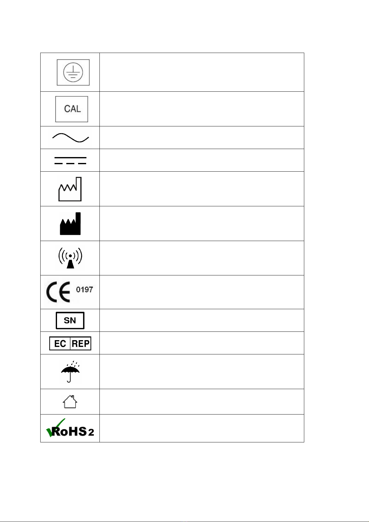
5. SAFETY SYMBOLS AND INFORMATION
The International Electrotechnical Commission (IEC) has established a set of symbols for medical
electrical equipment which classifies a connection or warning of any potential hazard.
The classifications and symbols are shown below. Save these instructions for your safety.
Degree of protection against electric shock: TYPE BF
Please observe operating instructions
General warning sign
General prohibition sign
General mandatory action sign
Caution
Waste Electrical and Electronic Equipment (WEEE)
The device could be sent back to the manufacturer for recycling or
proper disposal after their useful lives. Alternatively the device shall be
disposed in accordance with national laws after their useful lives.
/
"ON / OFF" key : Turn the power ON / OFF
Class II equipment
10
This symbol is used inside system.
Identifies the point where the safety ground of the system is fastened to
the chassis.
Do not open. This is for factory only.
Alternating current
Direct current
Date of manufacture
Manufacturer
Non-ionizing radiation
CE mark
Serial No.
Authorized representative in the European community.
Keep dry
For indoor use only
RoHS2

11
6. Guidance for Electromagnetic compatibility (EMC)
Details about the electromagnetic compatibility (EMC) of the ACCUNIQ BC300 are given below.
Before using the ACCUNIQ BC300, be sure to read and understand the following information.
1) Guidance and manufacturer’s declaration – electromagnetic emissions
The ACCUNIQ BC300 is intended for use in the electromagnetic environment specified below. The
customer or the user of the ACCUNIQ BC300 should assure that it is used in such an environment.
Emissions test Compliance Electromagnetic environment – guidance
RF emissions
CISPR 11 Group 1
The ACCUNIQ BC300 uses RF energy only for its
internal function. Therefore, its RF emissions are
very low and are not likely to cause any
interference in nearby electronic equipment.
RF emissions
CISPR 11 Class B
Harmonic
emissions
IEC 61000-3-2
Class A
Voltage
fluctuations/
flicker emissions
IEC 61000-3-3
Compliance
The ACCUNIQ BC300 is suitable for use in all
establishments, including domestic
establishments and those directly connected to
the public low-voltage power supply network that
supplies buildings used for domestic purposes.

12
2) Guidance and manufacturer’s declaration – electromagnetic immunity
The ACCUNIQ BC300 is intended for use in the electromagnetic environment specified below. The
customer or the user of the ACCUNIQ BC300 should assure that it is used in such an environment.
Immunity test IEC 60601 test
level
Compliance
level
Electromagnetic environment-
guidance
Electrostatic
discharge(ESD)
IEC 61000-4-2
±6kV: Contact
±8kV: Air
±6kV: Contact
±8kV: Air
Floors should be wood, concrete
or ceramic tile. If floors are
covered with synthetic material,
the relative humidity should be at
least 30 %.
Electrical fast
transition/burst
IEC 61000-4-4
±2kV: Power
supply lines
±1kV:
Input/output
lines
±2kV: Power
supply lines
±1kV:
Input/output
lines
Mains power quality should be
that of a typical commercial or
hospital environment.
Surge
IEC 61000-4-5
±1 kV
differential
mode
±2 kV common
mode
±1 kV
differential
mode
±2 kV common
mode
Mains power quality should be
that of a typical commercial or
hospital environment.
Voltage drops,
dips, and
fluctuations of
input power
supply line IEC
61000-4-11
<5 % UT
(>95 % dip in
UT)
for 0,5 cycle
40 % UT
(60 % dip in UT)
for 5 cycles
70 % UT
(30 % dip in UT)
for 25 cycles
<5 % UT
(>95 % dip in
UT)
for 5 sec
<5 % UT
(>95 % dip in
UT)
for 0,5 cycle
40 % UT
(60 % dip in
UT)
for 5 cycles
70 % UT
(30 % dip in
UT)
for 25 cycles
<5 % UT
(>95 % dip in
UT)
for 5 sec
Mains power quality should be
that of a typical commercial or
hospital environment. If the user
of the ACCUNIQ BC300 requires
continued operation during power
mains interruptions, it is
recommended that the ACCUNIQ
BC300 be powered from an
uninterruptible power supply or a
battery.

13
Magnetic field
of commercial
frequency
(50/60Hz)
IEC 61000-4-8
3 A/m 3 A/m
Power frequency magnetic fields
should be at levels characteristic
of a typical location in a typical
commercial or hospital
environment.
Note
UT is the a.c. mains voltage prior to application of the test level.

14
3) Guidance and manufacturer’s declaration – electromagnetic immunity 2
The ACCUNIQ BC300 is intended for use in the electromagnetic environment specified below. The
customer or the user of the ACCUNIQ BC300 should assure that it is used in such an environment.
Immunity test IEC 60601 test
level
Compliance
level
Electromagnetic environment-
guidance
Conducted RF
IEC 61000-4-6
Radiated RF
IEC 61000-4-3
3 Vrms
150 kHz to 80 MHz
3 V/m
80 MHz to 2,5 GHz
3 Vrms
3 V/m
Portable and mobile RF
communications equipment should
be used no closer to any part of the
ACCUNIQ BC300, including
cables, than the recommended
separation distance calculated from
the equation applicable to the
frequency of the transmitter.
Recommended separation
distance
d =1.2
d =1.2 80 MHz to 900 MHz
d =2.3 900 MHz to 2,5 GHz
where P is the maximum output
power rating of the transmitter in
watts (W) according to the
transmitter manufacturer and d is
the recommended separation
distance in meters (m).
Field strengths from fixed RF
transmitters, as determined by an
electromagnetic site survey,a
should be less than the compliance
level in each frequency range.b
Interference may occur in the
vicinity of equipment marked with
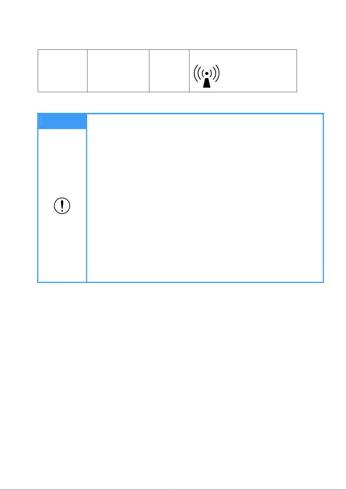
15
the following symbol:
Note
1. At 80 MHz and 900 MHz, the higher frequency range applies.
2 These guidelines may not apply in all situations. Electromagnetic propagation is
affected by absorption and reflection from structures, objects and people.
a Field strengths from fixed transmitters, such as base stations for radio
(cellular/cordless) telephones and land mobile radios, amateur radio, AM and
FM radio broadcast and TV broadcast cannot be predicted theoretically with
accuracy. To assess the electromagnetic environment due to fixed RF
transmitters, an electromagnetic site survey should be considered. If the
measured field strength in the location in which the ACCUNIQ BC300 is used
exceeds the applicable RF compliance level above, the ACCUNIQ BC300
should be observed to verify normal operation. If abnormal performance is
observed, additional measures may be necessary, such as reorienting or
relocating the ACCUNIQ BC300.
b Over the frequency range 150 kHz to 80 MHz, field strengths should be less
than 3 V/m.
16
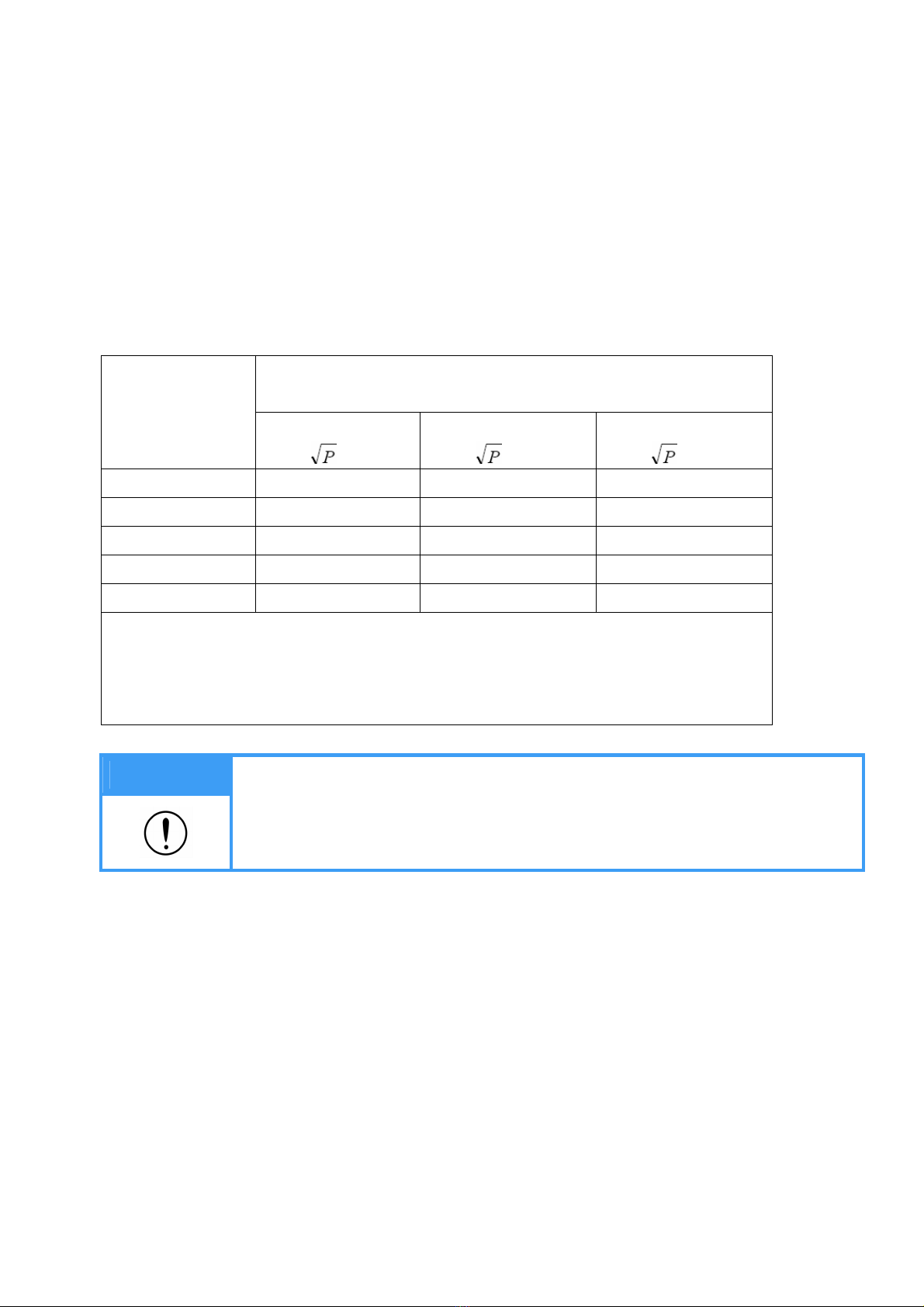
4) Recommended separation distances between portable and mobile RF communications
equipment and the ACCUNIQ BC300
The ACCUNIQ BC300 is intended for use in an electromagnetic environment in which radiated RF
disturbances are controlled. The customer or the user of the ACCUNIQ BC300 can help prevent
electromagnetic interference by maintaining a minimum distance between portable and mobile RF
communications equipment (transmitters) and the ACCUNIQ BC300 as recommended below,
according to the maximum output power of the communications equipment.
Separation distance according to frequency of transmitter
m
Rated maximum
output power
of transmitter
W
150 kHz to 80 MHz
d =1.2
80 MHz to 900 MHz
d =1.2
900 MHz to 2,5 GHz
d =1.2
0.01 0.12 0.12 0.23
0.1 0.38 0.38 0.73
1 1.2 1.2 2.3
10 3.8 3.8 7.3
100 12 12 23
For transmitters rated at a maximum output power not listed above, the recommended
separation distance d in meters (m) can be estimated using the equation applicable to
the frequency of the transmitter, where P is the maximum output power rating of the
transmitter in watts (W) according to the transmitter manufacturer.
Note
1. At 80 MHz and 900 MHz, the separation distance for the higher frequency
range applies.
2. These guidelines may not apply in all situations. Electromagnetic propagation
is affected by absorption and reflection from structures, objects and people.

17
ABOUT BODY
C
OMPOSI
TION
1. Body Composition
Human body consists of body fat and lean body. Lean body means non-fat constituents of human
body like body water, muscles, bones, etc.
Body water is divided into intra- and extra-cellular water and the ratio between them is controlled
and maintained within a certain range. Body fat is piled beneath the skin and between abdominal
organs. Body fat is hydrolyzed to make energy needed to normal physiological function when
energy supply through food intake is not sufficient, but excessive fat in the body itself is a kind of
disease and causes lifestyle diseases.
Healthy people maintain the balance of body composition in a steady proportion but unhealthy
people persons fail to keep this balance. When the balance in body composition is broken,
diseases like obesity, malnutrition, osteoporosis, etc. can be caused.
2. Obesity
Various methods can be used to assess obesity but the key factor in obesity assessment is the
amount of fat accumulated in the body.
In general, obesity is defined as the state of not only excessive weight compared with height
(visible obese) but also excessive body fat compared with weight (invisible or visible obese).
Strictly speaking obesity is the state that body fat occupies considerably high ratio to weight.
3. Necessity of Body Composition Analysis
Body Composition Analysis is a good indicator to find possible health problems. Body composition
analysis enables professionals to find obesity or imbalance in body composition at early stage and
helps subjects keep their body healthy. Body composition analyzer is a useful preventive
diagnostic device.
4. Waist to hip ratio
Waist to hip ratio (W.H.R.) shows the distribution of fat stored in one’s abdomen and hip. It is
simple but useful to assess body fat distribution. Body fat is stored in two distinct ways. They are
often called 'apple' and 'pear' type. Apple type shows bigger girth of waist than hip and pear type
has bigger girth of hip than waist. If body fat in abdomen increases more, the risk to
cardiovascular diseases, diabetes, etc. becomes higher.

18
5. Abdominal Fatness
Body fat is divided into subcutaneous fat and visceral fat. Visceral obesity is considered to be a
critical risk factor along with Percent of body fat.
Lipoprotein lipase can be easily activated in visceral fat, and it cause visceral fat to be dissolved
easily. Dissolved visceral fat goes into liver through the vessel and it cause fatty liver or increasing
lipid in the blood. It also elevates the risk of hyperinsulinemia, hypertension, and cardiovascular
disease.
Visceral fat generally occupies 10 ~ 20 % of body fat, and visceral obesity is assessed based on
the indicators below.
- the cross sectional fat area between L4 ~ L5 is 100 cm2 and over
- the visceral fat to subcutaneous fat ratio is 0.4 and over
- the waist to hip ratio (W.H.R.) is over 0.9 (male) / 0.85 (female)
- the circumference of waist is over 102 cm (male) / 88 cm (female)
Visceral fat increases after their 30s in men and after Menopause in women. It is more common
in men than women and the old than the young. Visceral fat tends to increase with aging.
Because the combustion rate per minute of visceral fat is higher than that of subcutaneous fat,
visceral fat can be easily reduced by exercise or dietary control in case of abdominal obesity.
W.H.R. is the ratio of waist to hip circumference and has relation to one’s figure.
6. Segmental Analysis
This device analyzes soft lean mass of five body parts; trunk, right arm, left arm, right leg, and left
leg. This function can be used as an assessment tool to evaluate the result of exercise or
rehabilitation treatment.
7. Age Matched of Body
It is the estimated physical age of the subject considering body composition analysis result,
gender, and biological age. This is calculated by comparing the optimal body composition based
on the gender and biological age of the subject with the actual analyzed body composition. It can
be used to evaluate the subject’s health and body development.

19
TERM
AND FUNCTION
OF EACH PART
1. Main Body
1) Front Part
▪ Color LCD screen
It displays the procedure and results.
▪ Handle Electrode
Handle Electrode measure the impedance by sending harmless electric current to the body.
Hold them with the hands during measurement.
▪ Key pad
Key pad consist of numeric buttons from 0 to 9, alphabet, ‘ ’, ‘ ’, ‘ ’, ' • ', 'CE', '◀', '▶',
'BACK', and 'NEXT'.
▪ Thermal Printer (Option)
Thermal printer allows the speedy and convenient printing.
Thermal printer (option)
Handle Electrode
Key Pad
Color LCD

20
2) Rear Part
▪ Blood pressure monitor (RS-232C) port: Connecting blood pressure monitor (OPTION) by
SELVAS Healthcare, Inc.
▪ Printer (USB(A)) port: Connecting the printer offered with this device.
▪ Computer (USB(B)) port: Connecting a computer.
▪ Adapter port (ADAPTER): Connecting an adapter.
▪ Power switch: It can be used to turn on/off the power.
▪ ZIGBEE port: In case of using wireless communication with computer, it can be used to
connect ZIGBEE (Wireless communication). Wireless connecting is possible
with Body Pass Plus or Easy Body Plus. (Wireless communication – Option)
When you choose a height meter as option, it will be connected to ZIGBEE port.
It is impossible to use both ZIGBEE (Wireless communication) and height meter.
When height meter is connected, you can not use wireless communication.
Blood Pressure monitor port
Printer port
Computer port
Adapter port Power switch
ZIGBEE port
Other manuals for ACCUNIQ BC300
1
Table of contents
Other SELVAS Healthcare Scale manuals


