Regulus PS 500 N25 User manual

www.regulus.eu
PS N25
PS N25
EN
Installation and Operation Manual
THERMAL STORES
PS 500 N25, PS 1000 N25, PS 1500 N25, PS 2000 N25,
PS 3000 N25, PS 4000 N25, PS 5000 N25

│2
CONTENTS
1 Description .................................................................................................................................................... 3
1.1 Models ............................................................................................................................................... 3
1.2 Tank Protection .................................................................................................................................. 3
1.3 Thermal Insulation ............................................................................................................................. 3
1.4 Connection points on the tank ........................................................................................................... 3
1.5 Packaging .......................................................................................................................................... 3
2 General Information ...................................................................................................................................... 3
3 Dimensions and Other Technical Data ........................................................................................................ 4
4 Operation ....................................................................................................................................................... 5
5 Typical Layout Example with Thermal Store .............................................................................................. 5
6 Installation and Commissioning .................................................................................................................. 7
6.1 Connection to heat sources .............................................................................................................. 7
6.2 Connection to a solar thermal system ............................................................................................... 7
6.3 El. heating element installation ......................................................................................................... 7
6.4 Commissioning .................................................................................................................................. 7
7 Installing Insulation on the Tank ................................................................................................................. 8
8 Maintenance .................................................................................................................................................. 10
9 Disposal ......................................................................................................................................................... 10
10 Warranty ......................................................................................................................................................... 10

3 │
1 - Description
PS N25 Thermal Stores are intended for storing and subsequent distribution of thermal energy from solid-fuel red
boilers, heat pumps, solar collectors, electric boilers etc. These tanks do not enable installation of heat exchangers,
only direct installation of an electric heating element. 230V or 3x230V/400V heating elements (2-12 kW output) can
be installed directly into the 2.5” connections. Tanks are tted with nine connections for heat sources and a heating
system, four connections for installing sensor sheaths and one connection for a safety valve. A 100mm thick insulation
for these tanks can be purchased as a separate item.
1.1 - Models
Seven models of 476, 929, 1506, 2007, 3022, 3991 and 4989 l capacity.
1.2 - Tank protection
The inner surface has no nish, no anticorrosion protection, the outer surface is lacquered in gray.
1.3 - Thermal Insulation
Thermal insulation is available as a separate item. For easier handling, the insulation shall not be tted on the tank
untilit reaches its denite place of installation. The insulation is made of eece, 100 mm thick, with a hard polystyrene
surface. It is closed by a quick lock.
1.4 - Connection points on the tank
8× side connections in a circular section of 90°, G 2.5“ F thread
1× top connection, G 2.5“ F thread
4× side connections for sensor sheaths, G 1/2“ F thread
1× connection for installation of a 3bar safety valve, G 1/2“ F thread
1.5 - Packaging
Thermal stores are delivered standing, each screwed to its separate pallet, packed in bubble wrap.
2 - General Information
This Manual is an integral and important part of the product and must be handed over to the User. Read carefully
the instructions in this Manual as they contain important information concerning safety, installation, operation and
maintenance. Keep this Manual for later reference. The appliance shall be installed by a qualied person according to
valid rules and Manufacturer‘s Instructions, otherwise the Warranty is null and void.
This appliance is designed to accumulate thermal energy of heating water and distribute it subsequently. It must be
connected to a heating system and heat sources.
Using the thermal store for other purposes than above described is forbidden and the manufacturer accepts
no responsibility for damage caused by improper or wrong use. The thermal store must not be used as a hot
water storage tank!

│4
3 - Dimensions and Other Technical Data
Type - model PS 500 N25 PS 1000 N25 PS 1500 N25 PS 2000 N25 PS 3000 N25 PS 4000 N25 PS 5000 N25
Tank code a19272 19376 19379 19370 14454 14457 14331
Insulation code b19274 19378 19381 19372 19345 19352 19358
Storage volume [l] c476 929 1506 2007 3022 3991 4989
Empty weight [kg] d93 119 185 218 309 423 485
Tipping height [mm] V1 1940 2120 1965 2055 2180 2490 2970
Dimensions [mm] ø D1 800 1000 1300 1450 1700 1800 1800
ø D 600 800 1100 1250 1500 1600 1600
B1 1605 1678 1465 1498 1545 1815 2315
B2 245 320 355 390 445 465 465
H1 1915 2080 1885 1955 2065 2355 2855
H2 245 320 355 390 445 465 465
C1 1615 1690 1475 1510 1565 1835 2335
C2 560 635 625 660 545 600 925
C3 1270 1345 1175 1210 1445 1705 1855
T1485 1560 1355 1390 1265 1490 2105
P450 435 450 450 715 780 670
U1 1605 1678 1465 1498 1545 1815 2315
U2 435 510 535 582 645 675 775
U3 1155 1230 1095 1130 1185 1375 1705
U4 685 760 715 750 805 905 1075
U5 1385 1460 1255 1278 1345 1605 2005
Tank code: .............................................................................. a
Insulation code: ...................................................................... b
Storage volume: ..................................................................... c
Max. working pressure in tanks PS 500 N25 a PS 1000 N 25: ... 4 bar
Max. working pressure in tanks PS 1500 N25 ÷ PS 5000 N25: .. 3 bar
Max. working temperature in tank: ......................................... 95 °C
Empty weight: ......................................................................... d
Tipping height without insulation: ........................................... V1
Dimensions
CONNECTIONS
pos. connections
Heat sources
B1 G 2,5" F
B2 G 2,5" F
Heating system
H1 G 2,5" F
H2 G 2,5" F
Control and safety
C1 G 1/2" F
C2 G 1/2" F
C3 G 1/2" F
TG 1/2" F
PG 1/2" F
Control and safety
U1 G 2,5" F
U2 G 2,5" F
U3 G 2,5" F
U4 G 2,5" F
U5 G 2,5" F
øD1
øD
H1

5 │
4 - Operation
In a thermal store, heating water can be heated up by various types of hot-water boilers, renewable energy sources
(heat pumps, solar collectors), or possibly also by electric heating elements.
The thermal store is connected to the energy source using a G 2.5“ connection tting. Should the tank be connected to
a solar thermal system, a heat exchanger shall be used for the connection because heating water is not used as the heat
transfer uid in a solar thermal system. The individual tank outlets are tted according to the circuits to be connected.
5 - Typical Layout Examples with Thermal Store
Example I.
Heat pump and electric heating element.
KEY
1 – Regulus heat pump (RTC, CTC)
2 – pump station for heat pump – CSE TC W iPWM MFB
3 – electric heating elements for heating system
4 – heating system expansion vessel
5 – collector/manifold, HV 60/125-2
6 – pump station for heating system 2 - CSE2 MIX
7 – pump station for heating system 1 - CSE2
8 – thermal store for central heating - PS xxx N+ (K+, N25)
ÚT – central heating (heating system)
KK – ball valve
ZV – check valve
AOV – automatic air vent valve
VK – drain valve
SVE – expansion vessel service valve
PV-ÚT – safety valve for heating system
MFB – Magnet Filterball
THERMOSTAT
BRAIDED HOSE
THERMOMETER
COMPENSATOR

│6
Example II.
Biomass boiler (replace insert/stove) and electric heating element.
KEY
1 – hot water storage tank
2 – el. heating element for DHW w. thermostat
3 – electric heating elements for heating system
4 – thermal store for central heating - PS xxx N+ (K+, N25)
5 – heating system expansion vessel
6 – boiler load unit – thermostatic
7 – biomass boiler (replace insert/stove)
8 – pump station for heating system - CSE MIX
9 – pump station for DHW heating – CSE OTS ZV
10 – pump station for DHW recirculation – CSE TVMIX ZV
11 – safety kit for HW storage tank
12 – DHW expansion vessel
SV – cold water
TV – hot water
CV – hot water recirculation
ÚT – central heating (heating system)
KK – ball valve
ZV – check valve
AOV – automatic air vent valve
PTR – pressure temperature relief valve
REDV – pressure reducing valve (optional)
VK – drain valve
SVE – expansion vessel service valve
PV-ÚT – safety valve for heating system
MFB – Magnet Filterball
F – lter
BVTS – safety relief valve of boiler cooling loop
THERMOSTAT THERMOMETER

7 │
6 - Installation and Commissioning
Installation shall meet valid rules and may be done by qualied staff only.
Defects caused by improper installation, use or handling are not covered by warranty.
After the tank is installed and connected to an existing heating system, it is recommended to clean the entire
heatingsystem using a suitable cleaning agent, e.g. BP 400.
Anti-corrosion protective liquid should be also used, e.g. BP 100 Plus.
6.1 - Connection to heat sources
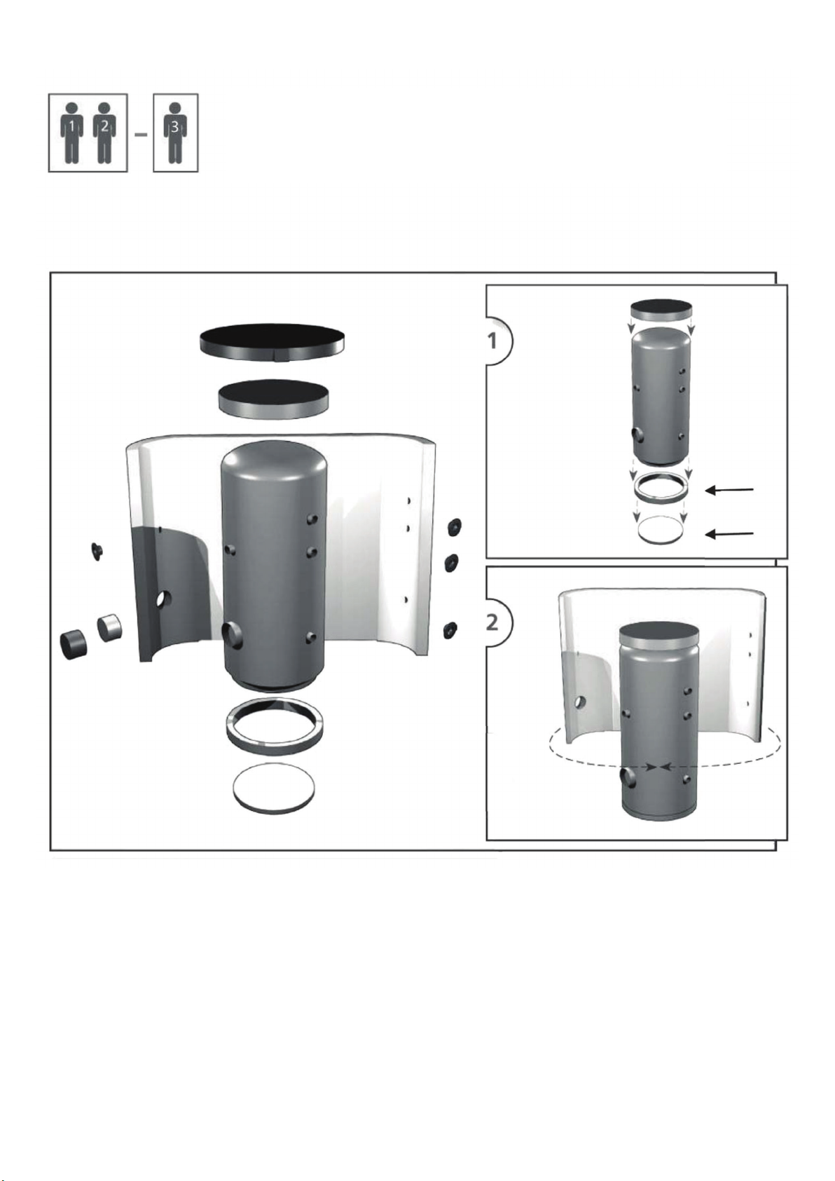
Place the tank on the oor, as close to your heat source as possible. Fit the insulation, cf. Installing Insulation on the
Tank. Connect the heating system according to the recommended connection layout - see Chap. 5.Install a drain valve
at the lowest point of the tank. Install an air vent valve at the highest point of the system. Insulate all the connecting
piping.
6.2 - Connection to a solar thermal system
This thermal store is primarily not designed to be connected to a solar thermal system. However, when needed, such
a connection can be done by means of a heat exchanger between the solar thermal system and the thermal store. In
such an event, all the connecting piping between the tank and this heat exchanger shall be thoroughly insulated.
6.3 - El. heating element installation
These thermal stores can be equipped with electric heating elements of output up to 12 kW depending on the volume of
the thermal store - see the table of max. output of heating elements in hot water tanks and thermal stores. They can be
connected either directly (elements with integrated thermostat) or via the controller of the entire heating system.
All electric heating elements shall be protected by a safety thermostat.
The electric heating element shall be wired by a professionally qualied person only.
6.4 - Commissioning
This tank is not designed for DHW heating.
The tank shall be lled up together with the heating system, respecting valid standards and rules. In order to minimize
corrosion, special additives for heating systems should be used. The quality of heating water depends on the quality of
lling water at commissioning, on the top-up water quality and on the frequency of topping up. This has a strong inuen-
ce on the lifetime of heating systems. Poor quality of heating water may cause problems like corrosion or incrustation,
esp. on heat transfer surfaces.
Fill the heating circuits with the appropriate uids and air-bleed the entire system. Check all connections for leaks
and verify the system pressure. Set the heating controller in compliance with the documentation and manufacturer’s
recommendations.
Check regularly proper function of all control and adjustment elements.

│8
7 - Installing Insulation on the Tank
Product description
Fleece insulation with a hard polystyrene surface, closed by a quick lock.
Warning
Insulation installation shall be done in two or three persons, depending on its size. The PU leather surface coated eece
insulation must not be installed at temperatures below 20 °C. If this cannot be avoided, the insulation shall be pre-
-warmed in another room to at least 20 °C. It is impossible to install insulation of lower temperature, there is a risk of
damage.
Do not use any tools for installation.
Keep away from open re.
Installing insulation
1. Put the bottom insulation under the tank and place the tank following installation instructions.
2. Wrap the insulation around the tank carefully. Check that the insulation adheres to its body perfectly. This can be
reached by rubbing and patting the insulation by hand from its centre evenly in both directions until the insulation
adheres to the tank’s surface completely and no bubbles are left.
3. Use the holes for connections as a rest during the insulation installation.
4. At least one person presses the insulation to the tank, pulling both ends together. The other person closes the quick
lock from the side.
5. Put on the upper insulation and cover.
6. Push on the covering plastic rosettes depending on the size of connections, or put on the ange plug(s) with insula-
tion.
7. Finish the tank installation in compliance with the respective instructions and valid standards and rules.
Warranty on insulation
The insulation is covered by a 24-month warranty. This period starts the next day after the insulation is sold.
□ Warranty shall become null and void if:
○ the procedure described in the Installation Manual was not respected,
○ the product was used for other purposes than intended.
□ Warranty does not cover:
○ usual wear and tear,
○ damage caused by re, water, electricity or another natural disaster,
○ defects caused by failure to use the product in compliance with its intended purpose, by improper use and
insufcient maintenance,
○ defects caused by mechanical damage to the product,
○ defects caused by tampering or incompetent repair.

9 │

│10
8 - Maintenance
If the tank is tted with a heating element, disconnect it from the mains rst. Clean the exterior of the tank with a soft
cloth and a mild detergent. Never use abrasive cleaners or solvents.
Check all tank connections for leaks.
9 - Disposal
Packaging shall be disposed of in compliance with the valid rules. When the product reaches the end of its life, it shall
not be disposed of as household waste. It shall be dropped off at a Local Waste Recycling Centre. Insulation shall be
recycled as plastic and the steel vessel as scrap iron.
10 - Warranty
This product is covered by warranty according to the conditions described in this Manual and according to the Warranty
Certicate. A Warranty Certicate is an integral part of the supply.

11 │

©2022 We reserve the right to errors, changes and improvements without prior notice.
REGULUS spol. s r.o.
E-mail: [email protected]
Web: www.regulus.eu
v1.3-11/2021
This manual suits for next models
6
Table of contents
Other Regulus Storage manuals