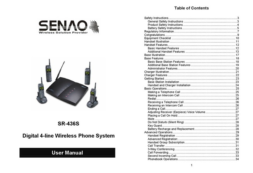
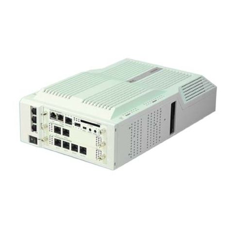
SENAO SP-428 User manual

SP-428 Series
Fully Integrated Wireless PABX in DECT System
User Manual

428 Series
User’s Manual
Contents
CONTENTS
1. Introduction..................................................................................................... 1-1
1.1 System Specification ................................................................................ 1-2
1.2 System Functions ..................................................................................... 1-3
1.3 Options…………………………………………………………………………...1-4
2. Installation....................................................................................................... 2-1
2.1 Before Installation ..................................................................................... 2-1
2.2 Installation of Central Unit........................................................................ 2-3
2.3 Installation of Remote Station(RBS)................................................... 2-6
2.4 Options
……………………………………………………………………………...2-7
2.4.1 Installation of Door Phone/Relay Functional Card ..............................................................2-8
2.4.2 Installation of Trunk Functional Card...................................................................................2-9
2.5 General Notes .......................................................................................... 2-10
3. DECT and SLT Operations ........................................................................... 3-10
3.1 Alarm Clock ............................................................................................. 3-10
3.1.1 Set Station Alarm ...............................................................................................................3-10
3.1.2 Clear Station Alarm............................................................................................................ 3-11
3.2 Auto CO Hunting ..................................................................................... 3-11
3.3 Broker’s Call/ Call Splitting .................................................................... 3-12
3.4 Call Forward............................................................................................. 3-12
3.4.1 Set Call Forward................................................................................................................3-12
3.4.2 Cancel Call Forward ..........................................................................................................3-13
3.4.3 Set Call Forward Inhibit .....................................................................................................3-13
3.5 Call Hold................................................................................................... 3-14
3.5.1 Place Call on Hold .............................................................................................................3-14
3.5.2 Take Hold Line Back..........................................................................................................3-14
3.6 Call Park................................................................................................... 3-15
3.6.1 Set Call Park......................................................................................................................3-15
3.6.2 Retrieve Call Park..............................................................................................................3-15
1

428 Series
User’s Manual
Contents
3.7 Call Pick-Up ............................................................................................. 3-16
3.7.1 General Pick-up.................................................................................................................3-16
3.7.2 Specific Pick-up. ................................................................................................................3-16
3.8 Call Transfer............................................................................................. 3-16
3.8.1 Ring Transfer. ....................................................................................................................3-16
3.8.2 Voice Transfer....................................................................................................................3-16
3.8.3 Busy Transfer ....................................................................................................................3-17
3.9 Do Not Disturb ......................................................................................... 3-17
3.9.1 Enable DND.......................................................................................................................3-17
3.9.2 Disable DND......................................................................................................................3-17
3.10 Digital Tapeless Answering Machine (DTAM)........................................ 3-18
3.10.1 Recording System OGM Message..................................................................................3-18
3.10.2 Listen DTAM voice segment............................................................................................3-19
3.10.3 Recording Personal OGM Messages..............................................................................3-20
3.10.4 DTAM General Operation................................................................................................3-20
3.10.5 Listen Your Message from Outside Area.........................................................................3-23
3.11 Door Phone and Door Lock .................................................................... 3-23
3.11.1 Call Door-phone ..............................................................................................................3-23
3.11.2 Open Door-lock: Idle .......................................................................................................3-24
3.11.3 Open Door-lock: While talking to Door Phone ................................................................3-24
3.12 External Call............................................................................................. 3-24
3.12.1 Make an External Call .....................................................................................................3-24
3.12.2 Make an VoIP External Call.............................................................................................3-25
3.13 Flashing on Trunk Line ........................................................................... 3-25
3.13.1 Send a flash pulse for SLT and Handset.........................................................................3-25
3.13.2 Send a flash pulse for Handset .......................................................................................3-25
3.14 Hot Line .................................................................................................... 3-26
3.14.1 Enable/Disable Hot Line..................................................................................................3-26
3.14.2 Set Hot Line Number.......................................................................................................3-26
3.15 Idle Station Hunting................................................................................. 3-27
3.15.1 Hot Line Activation...........................................................................................................3-27
3.15.2 Idle Station Hunting .........................................................................................................3-27
3.16 Intercom ................................................................................................... 3-27
3.17 Last Number Redial................................................................................. 3-27
3.18 Line Reservation / Line Queuing............................................................ 3-27
3.18.1 Specific Line Reservation ................................................................................................3-28
3.18.2 Auto Line Reservation. ....................................................................................................3-28
2

428 Series
User’s Manual
Contents
3.19 Cancel Line Reservation......................................................................... 3-28
3.20 Message Waiting ..................................................................................... 3-28
3.20.1 Message Waiting. ............................................................................................................3-28
3.20.2 Auto Call Back.................................................................................................................3-29
3.21 Override: Conversation Intrusion .......................................................... 3-29
3.22 Override: DND Override .......................................................................... 3-29
3.23 Paging
……………………………………………………………………………..3-29
3.23.1 Page All ...........................................................................................................................3-29
3.23.2 Answer Paging ................................................................................................................3-30
3.24 Speed Dialling: for External Calls Only ................................................. 3-30
3.24.1 Set Speed Dialling Number .............................................................................................3-30
3.24.2 Clear Speed Dialling Number..........................................................................................3-30
3.24.3 Speed Dialling (for operation)..........................................................................................3-31
3.25 Activate/ De-activate Station Lock ......................................................... 3-31
3.26 Toll Password .......................................................................................... 3-31
3.27 Warning Tone........................................................................................... 3-32
3.28 DISA Voice Access .................................................................................. 3-32
3.28.1 Recording ........................................................................................................................3-32
3.28.2 Play..................................................................................................................................3-34
3.29 Force Warning Tone ................................................................................ 3-35
3.30 Pulse/DTMF Dialling Conversion ........................................................... 3-35
3.31 Modem Switch ......................................................................................... 3-35
3.32 Supplement.............................................................................................. 3-36
3.32.1 Erase DISA/DTAM Block Messages ...............................................................................3-36
3.32.2 Day/Night Mode Switch ...................................................................................................3-36
4. Q & A................................................................................................................ 4-1
APPENDIX ............................................................................................................ A-1
A.1 Default Settings of Service Configuration................................................. A-1
A.1.1 System Configuration ........................................................................................................ A-1
A.1.2 Group Configuration .......................................................................................................... A-2
A.1.3 Trunk line Configuration..................................................................................................... A-2
3

428 Series
User’s Manual
Contents
A.1.4 Station Configuration ......................................................................................................... A-2
A.1.5 Door Phone Configuration ................................................................................................. A-3
A.1.6 Miscellaneous .................................................................................................................... A-3
A.2 Default Setting of Timer/Counter Programming ....................................... A-3
A.3 Default Setting of Toll Restriction .............................................................. A-5
A.3.1 Toll Restriction Assignments ..............................................................................................A-5
A.3.2 Call Screening Assignments .............................................................................................. A-5
A.3.3 Caller ID Assignments ....................................................................................................... A-5
A.4 Default Settings of Passwords and Access Codes................................... A-5
A.4.1 System Passwords Assignments....................................................................................... A-5
A.4.2 System Access Codes Assignments.................................................................................. A-5
A.5 Default Settings of SMDR and DTAM ......................................................... A-6
A.5.1 SMDR Assignments........................................................................................................... A-6
A.5.2 DTAM Assignments............................................................................................................ A-7
A.6 Default Settings of Station Programming.................................................. A-7
A.6.1 System Programming ........................................................................................................A-7
A.7 Default Setting on PBX Board .................................................................... A-7
A.8 Default Setting on Trunk Functional Card ................................................. A-9
APPENDIX B.......................................................................................................... B-1
B.1 External Devices Connection Diagram ...................................................... B-1
B.2 System Module ............................................................................................ B-2
B.2.1 Inside View of System..................................................................................................... B-2
B.2.2 Power Module ................................................................................................................. B-3
B.2.3 PBX module .................................................................................................................... B-4
B.2.4 DECT Module.................................................................................................................. B-6
B.2.5 DISA/DTAM Module ........................................................................................................ B-8
B.2.6 Expansion Cards............................................................................................................. B-8
B.3 External Device Installation .......................................................................B-11
B.3.1 SLT Installation...............................................................................................................B-11
B.3.2 Trunk Line Installation ....................................................................................................B-11
B.3.3 Door Phone Installation..................................................................................................B-11
B.3.4 Door Lock Installation.................................................................................................... B-12
B.3.5 Paging Installation......................................................................................................... B-12
B.3.6 Music Source Installation .............................................................................................. B-12
B.3.7 Backup Battery Installation............................................................................................ B-12
APPENDIX C.......................................................................................................... C-1
C.1 UPT (SYSTEM PROGRAMMING) Brief.......................................................... C-1
4

428 Series
User’s Manual
Contents
APPENDIX D.......................................................................................................... D-1
REMOTE PROGRAMMING MODE FROM USER’S SIDE..................................... D-1
D.1 This chapter provides the remote programming information with
step-by-step instruction. How to Enter Programming Mode from Customer
Side …………………............................................................................................ D-1
5

428 Series
User’s Manual
Introduction
1. Introduction
This chapter provides general information of the system, including system capacity and
specification.
428 Series System Configuration
The 428 series system is a wireless telephone system, which integrates DECT cordless
phones and analogue corded phones with PBX function. The whole system configuration
is described in Figure 1-1. This system allows connection with 4 PSTN lines (expandable
up to 8 PSTN lines), 2 SLTs (Single Line Telephones), 28 DECT handsets and other
optional functions, such as DISA (Direct Inward System Access)/DTAM (Digital
Tapeless Answering Machine), door-phone and relay control.
Loud Speaker
Music Source
PC Console
SMDR Printer
FAX
4 u
p
to 8 C.O.
PSTN Door Phone
Modem
Cord
Phone
Door Lock
DECT Handset
428
48VDC
2B+D
1 Km
428+
428+
Remote Base
Station (BS1)
Re
p
eater
BS3
BS2
Central Unit
428 Series DECT Telephone System
Figure1-1 System configuration
For the enhanced model, 428 plus system, it provides extra 3 Remote Base Stations to
increase the system capacity and radio coverage. The total simultaneous users of DECT
handsets are also extended up to 18 .
To overcome dead zone area of communication, it also can be equipped with repeaters that
have wireless connections to Remote Base Station, just as the repeater and handset have
wireless connection.
In compliance with DECT GAP(Generic Access Profile), 428 series system can be
inter-operable with the DECT handsets of other brands.
1-1

428 Series
User’s Manual
Introduction
The 428 series system is divided into 428 single cell system (called 428) and 428 plus
multi-cell system(called 428+). The Central Unit of 428 system has basic capacity of
- 4 trunks to PSTN.(expandable up to 8)
- 2 SLTs to analogous facilities, such as telephone 、fax and modem.
- One base built in and up to 28 registered handsets and 6 handsets simultaneous
conversation to be supported.
- SMDR helps to analyze and control costs by recording and printing outgoing
messages
- Paging to external speakers and external hold music sources.
- General PBX functions including DISA, DTAM, and caller ID.
To expand its capabilities, the system can be equipped with piggyback board to support
- 2 Door phones and 3 relays interface. Provide home security with using SLT or
handset to communicate with visitors.
- Additional 4 trunks card for increasing PSTN trunk lines of the system up to 8 lines.
1.1 System Specification
Model No.
Description 428 system 428+ system
Number of DECT Handsets 28 28
Number of Single Line Telephones 2
Trunk Port 4, expandable up to 8
RS-232 1
DISA Voice 1 min.
Voice Mail (DTAM) 100 min
Base-station Numbers 1 4
Door Phone Interface 2(additional)
Relay Control 3(additional)
Caller ID DTMF/FSK
Auto Fax Switch 1
Direct Modem Switch 1
Power Failure Transfer 1
Music Input Interface Input Impedance: 10Kohms, Input Level 0.7Vmax
External Broadcasting Interface Output impedance: 600Ohms, Output Level: 0.7V
Internal Battery (mounted on the Main
Board) Voltage : 3VDC
External Battery (to install outside the
cabinet) Voltage : 24VDC 7.0 Ah
1-2

428 Series
User’s Manual
Introduction
Power Requirement 110 – 240Vac 50Hz-60Hz 1.5Amax
220V AC10% 50Hz
Temperature (Operating) 0 ~ 40℃
Humidity (Relative) 30% ~ 90%
Reg. Phone Line Loop Resistance Country adapted
Dimension (mm) ( net ) 340(L)x268(W)x88(H)
Weight (Kg) 2.3
1.2 System Functions
Alarm Clock
Auto Busy Redial
Auto Trunk Line Hunting
Broker’s Call
Call Conference
Call External/Intercom
Call Forward
Call Hold
Call Park
Call Pick-up
Call Transfer
Caller ID
Call Screening
Day/Night Service
DND (Do Not Disturb)
DISA
Door Phone/Door Lock
DTAM (Digital Tapeless Answering Machine)
Flash Time Setting
Flexible Ringing Assignment
Group Management
Hot Line
Idle Station Hunting
Intercom Auto Rely
Intercom Non-blocking
Last Number Redial
Line Reservation/Queuing
Listen to Background Music
Long Speech Warning/Restriction
Message Waiting
Night Trunk Line Transfer
Override: Conversation Intrusion
Override: DND
1-3

428 Series
User’s Manual
Introduction
Broadcasting
Power Failure Phones
Private Line
Pulse/DTMF Dial Conversion
Real Time Clock Setting
Relays
Station Lock
SMDR (Station Message Detail Record)
Station Ring Type Setting
Access Codes Assignment
Password Assignment
Toll Password
Toll Restriction
Warning Tone
1.3 Options
Wireless remote base station------------ needs using 428 plus Central Unit.
Door phone and Door lock interface--- needs Door phone/relay functional card
Expansion 4 trunk lines-------------------needs Trunk functional card
External Battery--------------------------- 24V/7A Battery installed outside the cabinet
to support the Central Unit
1-4

428 Series
User’s Manual
DECT and SLT
Operations
2. Installation
2.1 Before Installation
SAFETY INSTRUCTIONS
1. Please read these safety instructions carefully.
2. Warning: This equipment must only be installed and maintained by service personnel.
3. Please keep this User’s Manual for your reference.
4. Please disconnect this equipment from AC outlet before cleaning. Don’t use liquid or sprayed
detergent for cleaning. Use moisture sheet or cloth for cleaning.
5. For pluggable equipment, the socket-outlet shall be installed near the equipment and shall be easily
accessible.
6. Please keep this equipment from humidity.
7. Install this equipment on the good position; Any dropping or falling would cause the equipment
damaged.
8. Make sure the voltage of the power source when connecting the equipment to the power outlet.
9. Avoid people’s stepping on the power cord; Do not place anything on the power cord.
10. All cautions and warnings on the equipment should be noted.
11. If the equipment is not used for a long time, disconnect the equipment from mains to avoid being
damaged by transient overvoltage.
12. Keep the equipment cleaned and dried.
13. Do not open the equipment. For safety reason, the equipment should only be opened by qualified
service personnel.
14. The DC port on the remote unit shall connect to TNV-1 approved devices.
2-1

428 Series
User’s Manual
DECT and SLT
Operations
15. If one of the following situations happens, get the equipment checked by a service personnel:
a. The Power cord or plug is damaged.
b. Liquid has dropping into the equipment.
c. The equipment has been exposed to moisture.
d. The equipment does not work well or you can not get it worked according to User’s
manual.
e. The equipment has dropped and damaged.
f. If the equipment is broken.
16. DO NOT LEAVE THIS EQUIPMENT IN AN ENVIRONMENT UNCONDITIONED, WHERE
THE STORAGE TEMPERATURE IS OVER 60°C(140°F), IT MAY DAMAGE THE EQUIPMENT.
17. The power supply can be operated under the ambient temperature of 40ºC.
18. The Earthing wire has to connect to safety
ground
by
screw
and
star
washed
before
install
the
equipment.
19. Connection of the Music on hold port and Pager port on this equipment must be to
SELV approved circuits.
20. CAUTION: There is hazardous voltage when connected Door Lock System.
Disconnect the power system before connected the Door Lock System.
21. CAUTION: Danger of explosion if battery is incorrectly replaced.
Replace only with the same or equivalent type recommended by the manufacturer.
Dispose of used batteries according to the manufacturer’s instructions.
2-2

428 Series
User’s Manual
DECT and SLT
Operations
2.2 Installation of Central Unit
Figure 2-1shows the exterior of 428 series Central Unit.
Brand
428
front view side view
1
2
RS232
}
3
4
5
6
7
8
10
9
Figure 2-1 428 series Central Unit
1. Antenna:Should be connected to the Central Unit.
2. Registration button::When press the button, the Central Unit will enter into the
registration mode.
3. Trunk LED:LED will light up when the trunk is used.
4. Power LED:When Central Unit is working correctly, the power LED flashes at a
cadence of every second.
5. RS232 port:Connection for UPT or SMDR device.(e.g. printer or PC terminal.)
6. Audio output port:Connection for speaker terminal.
7. Audio input port:Connection for music source (e.g. radio).
CAUTION: Connection of the Music on hold port and Pager port on this equipment must be
to SELV approved circuits.
8. Power switch::The switch for system power supply.
9. Power Cable Input:Plug in the Central Unit
2-3

428 Series
User’s Manual
DECT and SLT
Operations
10. -Cable outlet::Outlet for the cables of trunks, SLTs, RBSs, Door phones & relays, and
Earthing wire.
-Earthing wire: Connect the grounding wire (green/yellow) to the ground. The Earthing wire
has to connect to safety ground by screw and star washed before install the equipment
Installation Steps
Step 1:Please check the safety instructions carefully before installation.
Step 2:Check the items of each package set.
The package of Central Unit includes the following items:
Central Unit
Main power cord (The plug may be different depending on countries)
A bag with;
- screws
- Quick Connection Block.(Cables and RJ11 connectors for Remote Base
station are not included)
Power adapter (48V/60W).
A mounting template.
User’s Manual.
Step 3:Preparation for Installing and Wiring of Central Unit
Remove the 2 screws on the top side of the Central Unit and the one screw on
the bottom side of the Central Unit.
Open the Central Unit. Figure 2-2 shows the Central Unit with all the functional
boards and the connectors.
Wiring
- Prepare cables, RJ11 plugs, and the Quick Connection Block: 4 pins x 5, 2
pins x 3. (AWG24 twist cables are suggested)
- Connect cables with the bases, trunks, SLTs, door phones and relays
(usually with RJ11 plugs)
- Fix Quick Connection Block on the other end of cables, and plug into their
correct positions.
- Make the cables inside the Central Unit pass through the cable outlet (see
Figure 2-2). Now you can close the Central Unit and fix it with 3 screws.
- Connect the grounding wire (green/yellow) to the ground. The Earthing wire
has to connect to safety ground by screw and star washed before install the equipment.
Step 4:
Insert battery cells into the handset (1.2V x 3 Ni-MH AAA).
Power on the Central Unit and enter into the registration mode (by pressing the
registration button, or by using UPT console).
Register your handsets according to the Handset Manual.
2-4

428 Series
User’s Manual
DECT and SLT
Operations
Remote base 1
Remote base 2
Remote base 3
Trunk 4
Trunk 3
{
{
Trunk 2
Trunk 1
{
{
SLT 2
SLT 1
{
{
{
{
{
Screws
Cables outlet
24V battery input
Screws
Expansion Cards
Doorphon/Relay Card
or
4-Trunk Card
connect the grounding wire
(green/yellow) to the ground
Figure 2-2 Connection of the Central Unit
IMPORTANT
To keep the system default value,the manufacturer strongly recommends the dealer to do
the following reset procedure at first installation.
Step 1: Remove the front cover of Central Unit.
Step 2: Power on Central Unit and waiting for 1 minute for the system becoming
stable.
Step 3: Press the registration button on the DECT board of system. Holding down
the button about 15 seconds until the LED of DECT board becomes steady
on/off for a while (within approximately 10 seconds). After system resetting
DECT completed, the LED will start to flash again.
Step 4: Use UPT setting to do UPT [1-43] item in Selection 1 (system reset).
Step 5: Power off Central Unit to clear all temporary information. Restart the
system with default setting.
Before closing the front cover of the Central Unit, make sure you have fastened
all the cables and connectors. The power LED will light up when you power on
the Central Unit; but the RUN LED indicator of the Central Unit will be flashing
quickly. Wait for 1 minute, and then the system will work normally (the RUN
2-5

428 Series
User’s Manual
DECT and SLT
Operations
LED indicator will flash slowly).
2.3 Installation of Remote Station(RBS)
Figure 2-3 shows the outline of RBS. The RBS is connected to the Central Unit by the
AWG24 twisted pair cable. Also the power of RBS can be obtained by the twisted pairs cable
from the Central Unit. The slide connector is 4-pin RI11 jack. The distance between RBS and
the Central Unit has a maximum of 1 Km.
Installation Steps:
Step 1:Choice the location for your RBS. (Mount the RBS on places and positions as
determined in your system configuration plan. The RBS must be placed where the
antenna is not hindered by thick wall or metal objects)
Step 2:Measure the distance between the RBS and the Central Unit. Cut the cable based on the
length as you needed.
Step 3:Prepare the connectors RJ11 for RBS, and 2-pin Quick Connection Block for the
Central Unit.
Note: The RJ11 (DC) port on the remote station (RBS) shall connect to TNV-1
approved devices.
Step 4:Position the RBS and fasten it with screws. Connect the antennas with the RBS. Plag
the connector into the RBS. When the RBS is under the normal operation, the LED
will become flashing.
The following optional cards can be used to enhance the function of the Central Unit
function. They are Door Phone/Relay Functional card and Trunk Functional card.
2-6

428 Series
User’s Manual
DECT and SLT
Operations
Figure 2-3 Remote Base Station
Run LED
RJ11 connector
2.4 Options
The following optional cards can be used to enhance the function of the Central Unit
function. They are Door Phone/Relay Functional card and Trunk Functional card.
2-7

428 Series
User’s Manual
DECT and SLT
Operations
2.4.1 Installation of Door Phone/Relay Functional Card
Door phone/Relay Card
Door phone 2 {
{
Door phone 1
Relay 2 Relay 1Relay 3
Figure 2-4 Connection of Door Phone/Relay Card
Before installing one of optional cards, you should turn off power firstly.
Connection of Door Phone/Relay Card is according to the installation steps of the Central
Unit as shown in figure 2-4.
2-8

428 Series
User’s Manual
DECT and SLT
Operations
2.4.2 Installation of Trunk Functional Card
Trunk 8
{
Trunk 7
{
Trunk 6
{
Trunk 5
{
Caller ID module
Trunk Functional Card
Figure 2-5 Connection of Trunk Functional Card
Before installing one of optional cards, you should turn off power firstly.
Connection of Trunk Functional Card is according to the installation steps of the Central Unit
as shown in figure 2-5.
Warning
The position of all jumpers has been setting well before shipment. Do not attempt
to change the jumpers on the boards by yourself.
2-9

428 Series
User’s Manual
DECT and SLT
Operations
2.5 General Notes
1. The backup battery with 24V DC will supply the power to the Central Unit
automatically once the main power failed.
CAUTION: Danger of explosion if battery is incorrectly replaced.
Replace only with the same or equivalent type recommended by the manufacturer.
Dispose of used batteries according to the manufacturer’s instructions
2. If you want to install a modem to the Central Unit, you should connect the
modem to the 1st SLT port (see Figure 2-2).
3. To save your system’s data, the Lithium Ion battery of the PBX board should
be checked and replaced once a year.
4. When you forgot the system password, or the system programming was failed
since the baud rate of RS232 port was not conformed to UPT’s required, the
Central Unit can be reset to return to default setting. Follow the below steps to
reset the system.
4.1 Turn off power switch.
4.2 Remove the battery jumper JP5 for 10 seconds (refer to Appendix. A.7
Default Setting on PBX Board)
Before power on the Central Unit, please make the JP5 short (return to JP5’s
original status) to recall the system data. So when resetting occurs, all
programmed features will be reset to factory default setting.
3. DECT and SLT Operations
This chapter provides the operation information of DECT handset and SLT with step-by
step instruction.
3.1 Alarm Clock
Set station alarm timing, up to 3 sets.
3.1.1 Set Station Alarm
(a) Off-hook handset
3-10
Other manuals for SP-428
1
This manual suits for next models
1
Table of contents
Other SENAO Telephone System manuals
Popular Telephone System manuals by other brands
GTel
GTel 700 Series Troubleshooting
Panasonic
Panasonic KX TS208W operating instructions

TelcoBridges
TelcoBridges TMP5900 System installation guide
Panasonic
Panasonic KXTG5243 - KXTG5240M TOT 3 H/S operating instructions

AT&T
AT&T MERLIN LEGEND Data planning forms
Lucent Technologies
Lucent Technologies MERLIN LEGEND Release 6.0 System programming and maintenance
