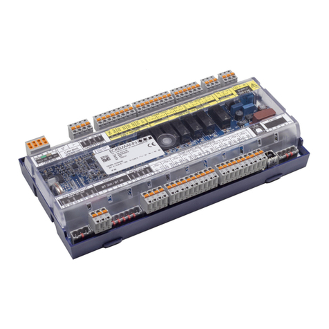
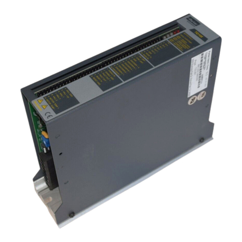
Sencon BCM500 User manual

BCM500
BODYMAKER CONTROL MODULE
RELEASE 1.1
Instructions &
Re erence
Manual

©
2012 Sencon Incorporated Page 1 BCM500/387 Bodymaker System
BCM500: DESCRIPTION
ALUMINUM-ON-PUNCH BODYMAKER SENSOR SYSTEM
T e Aluminum-on-Punc Bodymaker Sensor System detects t e presence of wall-ironed aluminum on t e
forming punc of a bodymaker. T e system is made up of a specialty sensor, t e 387, and a control module,
t e BCM500. T e system automatically compensates for t e magnetic properties of t e punc and mounting
ardware, eliminating t e need for a different sensor for eac punc composition. T is also eliminates
problems associated wit magnetic variations attributed to carbide batc tolerances, and minimizes t e effect
of variations due to temperature. T e system profiles t e punc , w ic allows t e sensor to accurately detect
tearoffs and s ort cans before t e punc is fully extended, t us providing more time to stop t e mac ine. T e
Sensor System detects aluminum over a variety of punc materials, making it ideal for plants c anging from
one punc type to anot er.
T e Bodymaker Sensor System offers two modes for stopping t e bodymaker, immediate stop and timed
stop. T e immediate stop mode stops t e mac ine w en a can defect is detected. T e module immediately
opens two transistor switc es t at can interrupt 2 Amperes at 24 Volts w en a defect is detected. T e timed
stop mode sync ronizes stopping t e mac ine wit t e leading edge of t e backstop window.
T e Bodymaker Sensor System is not applied t e same way a typical absence/presence proximity sensor is
applied. T e mac ine control logic must be altered to do t e calibration function of t e sensor. T is allows
t e sensor to calibrate to t e punc material and to profile t e punc . Four or more dry strokes (mac ine
strokes wit out cans in process) are required to calibrate t e sensor.
T e BCM500 expands t e capabilities of t e 387-S1 Bodymaker Sensor System. T e module supports t e
original s ort can and tearoff detection and supports dome jam detection and t e airstrip function. T e 387
sensor design is en anced wit extended calibration capabilities. T e sensor now works wit ceramic
punc es t at ave steel nose pieces. T e sensor also maintains calibration information internally in
EEPROM, eliminating t e need to recalibrate every time t e power to t e sensor cycles.
T e 9H-387 sensor as an integral cable and t e 11H-387 sensor is terminated using a quick disconnect
cable. A ose fitting designed to accept 0.75" I.D. [19.1 mm] ydraulic tubing surrounds t e connector. Use a
stainless steel ose clamp to provide a positive mec anical and ydraulic seal of t e ose to t e fitting. T is
aids in s ielding t e sensor and connector from t e bodymaker coolant.
Sensors ot er t an a 387 can be used wit t e BCM500. Consult t e factory for applications w ere t e
BCM500 is to be used wit existing Sencon 287 style bodymaker sensors.

©
2012 Sencon Incorporated Page 2 BCM500/387 Bodymaker System
DIMENSIONS
9H-387 Sensor
11H-387 Sensor
BCM500 Module

©
2012 Sencon Incorporated Page 3 BCM500/387 Bodymaker System
SPECIFICATIONS
Input Supply Voltage
Module
24 VDC
±
2.4 VDC
Input Supply Current
Module
400 mA Plus Load Current at 24 VDC
Module
Signal Inputs
Configuration
Source Active High) or Sink Active Low)
Voltage
Range
Minimum
-0.7 VDC
Maximum
Input Supply Voltage Value
Threshold
High State
55% of Input Supply Voltage
Low State
45% of Input Supply Voltage
Impedance
5 kΩ
Allowable Leakage
400 µA
Reverse Polarity
Sensor
Protected
Case Isolation
Sensor
200 VDC
Storage Temperature
Module
─ 40
º
F to +185
º
F [─ 40
º
C to +86
º
C]
Sensor
─ 40
º
F to +185
º
F [─ 40
º
C to +86
º
C]
Operating Temperature
Module
+32
º
F to +158
º
F [0
º
C to +70
º
C]
Sensor
+32
º
F to +158
º
F [0
º
C to +70
º
C]
Environment
Module
Requires mounting in a NEMA 12 or equivalent control
cabinet, removed from direct contact with moisture or hydraulic
fluids.
Sensor
Environmentally sealed to withstand the effects of vibration,
humidity, EMI, fungus, hydraulic fluid and dust.
GENERAL CHARACTERISTICS
Weight
Module
1 lb [450 g]
Sensor
5 oz. [140 g]
Case
Module
Polycarbonate
Sensor
Stainless Steel
Termination
Module
Screw terminals recessed to protect against accidental contact.
Sensor
Quick Disconnect with Hose Fitting - Use ONLY the mating connector available
through Sencon. Other connectors which appear to be equivalent may not be
compatible. Refer to Technical Data Sheet # 096-00007-xx Cables for DC
Sensors).

©
2012 Sencon Incorporated Page 4 BCM500/387 Bodymaker System
SENSOR OPERATING CHARACTERISTICS (RANGE TO TARGET)
Punch Material
Aluminum on Carbide
Punch Nickel Binder)
Aluminum on
Steel Punch
Aluminum on
Ceramic Punch
Aluminum on Carbide
Punch Cobalt Binder)
Sensing Range
0.065" to 0.100"
[1.7 to 2.5 mm]
0.065" to 0.300"
[1.7 to 7.6 mm]
0.150" to 0.250"
[3.8 to 6.4 mm]
0.065" to 0.180"
[1.7 to 4.6 mm]
Setting Distance
0.080" [2.0 mm]
0.205" [5.2 mm]
0.200" [5.1 mm]
0.120" [3.0 mm]
MODULE SOLID STATE SWITCH OUTPUT CHARACTERISTICS
Maximum Load
40 mA, Typical ON resistance at 25 mA is 25 Ω
500 mW maximum power through the switch
Voltage Range
0 to 240 VAC peak) or 0 to 240 VDC
Output Type
Bi-directional, isolated solid state switches.
Output Configuration
Suitable for DC source, DC sink, or AC.
MODULE TRANSISTOR SWITCH OUTPUT CHARACTERISTICS
Maximum Load
2 A DC Resistive/Inductive
Voltage Range
-0.7 VDC to 30 VDC
Voltage Drop
0.6 VDC at 1 A, 0.9 VDC at 2 A
Short Circuit Protection
Momentary 10 seconds)
Output State
Determined by the operating state. Refer to the `Operation' section of this TDS for
details.
Output Configuration
Optically Isolated FET Transistor Switch, Conductive in the Active State

©
2012 Sencon Incorporated Page 5 BCM500/387 Bodymaker System
INSTALLATION
MECHANICAL INSTALLATION
BCM500 Module Mounting
T e BCM500 controller is designed to be mounted in a
control cabinet, protected from moisture and ydraulic
fluids. T e unit may be mounted using a 35 mm DIN rail or
wit two fasteners. Recommended screw fasteners are #8
or M4.
387 Sensor Mounting
T e sensor must be rigidly mounted as
s own in t e diagrams. Use t e table
below for t e proper setting distance
between t e sensor and t e punc . T e
centerline of t e sensor must be
perpendicular to t e centerline of t e
punc and must pass t roug t e center
of t e punc . Make sure to seat fully and
tig ten t e cable connector on t e 11H-
387 sensor. Also install and clamp t e
ydraulic tubing over t e fitting.
Punch Material
Aluminum on Carbide
Punch Nickel Binder)
Aluminum on
Steel Punch
Aluminum on
Ceramic Punch
Aluminum on Carbide
Punch Cobalt Binder)
Setting Distance
0.080" [2.0 mm]
0.205" [5.2 mm]
0.200" [5.1 mm]
0.120" [3.0 mm]

©
2012 Sencon Incorporated Page 6 BCM500/387 Bodymaker System
ELECTRICAL INSTALLATION
T e inputs and outputs to t e BCM500 are s own ere. Electrical connection is made to t e unit wit screw
terminals. T e terminals are recessed to reduce t e c ances of accidentally contacting t em.
T e 0V, 0VI, and 0VS terminals are common to eac ot er. However, do not use t e 0VI or 0VS terminals for
power loads. T ey are intended for low level signals only. T e outputs are optically isolated from t e supply
voltage and t e inputs. T e COM terminal can be connected to an AC lead, to a DC lead, to t e 0V terminal,
or to t e +V
IN
terminal.

©
2012 Sencon Incorporated Page 7 BCM500/387 Bodymaker System
387 Sensor Interconnection
Make sure to seat fully and tig ten t e
cable connector on t e 11H-387 sensor.
Also install and clamp t e ydraulic tubing
over t e fitting. Ot erwise, liquid may
infiltrate t e connector and degrade
performance.
Note: Consult t e factory for Sencon
287 style sensor interconnection.
DC Signal Inputs
Configure t e input signals as s own in t e diagram below. Settings are made wit minijumpers accessible
under t e top cover of t e unit. Remove t e top cover by inserting a flat screwdriver blade in t e slot s own
and rotating t e blade to `pop' t e cover off. T is operation MUST be done wit power off to avoid damaging
t e unit.
Note: Alternative input setups are possible. Consult t e factory for details.

©
2012 Sencon Incorporated Page 8 BCM500/387 Bodymaker System
If an input is active ig , t e flow of current at t e input terminal is ON, and no current flow at t e input
terminal is OFF. T e reverse is true if an input is active low. T e transition from OFF to ON is t e leading
edge of t e signal. T e transition from ON to OFF is t e trailing edge of t e signal.
Solid State Switch Outputs
T ese outputs are optically isolated from t e supply voltage. T erefore, t e COM terminal is floating and can
be connected to any reference t at falls wit in t e specified voltage range.
FET Transistor Switch Outputs
T ere are t ree FET transistor switc es for control of t e
bodymaker clutc /brake solenoids and t e air strip solenoid. T e
contacts are FET transistors t at are optically isolated from t e
internal power supply.
IMPORTANT SAFETY NOTICE
The transistor switches provided with this unit must not be the only means o controlling the
bodymaker clutch mechanism. Good design practice dictates the use o sa ety lockouts on any
device that starts and stops automatically that can cause personal injury to operating or maintenance
personnel. The BCM500 must be used only with industry approved sa ety lockout contacts, otherwise
serious personal injury may result.

©
2012 Sencon Incorporated Page 9 BCM500/387 Bodymaker System
OPERATION
MODULE SIGNAL INPUTS
T e Bodymaker Sensor System requires t e ten inputs described ere. T ese inputs are not optically isolated
from t e BCM500 internal power supply.
Input
Description
SCT
T e S ort Can Timing window is active w en t e punc is in position for sensing. T e
trailing edge of t e window signal corresponds to t e can body trimline.
BST
T e Back Stop Timing window allows a sync ronous stop of t e mac ine. T e clutc
outputs open on t e leading edge of t is signal in t e Timed Stop mode.
AST
T e Air Strip Timing window is active during t e stroke for t e period t at allows t e can to
be blown off t e punc .
DJI
T e BCM500 c ecks t e Dome Jam Input from t e end of t e SCT window until t e end of
t e AST or BST windows. T erefore, eit er of t ese windows must be active just past 180
degrees of t e mac ine cycle to detect a dome jam.
RES
T e Reset/Override input clears all faults and closes t e appropriate output switc es. W ile
t e Reset/Override input is active, no tearoffs, s ort cans, or dome jams are detected. After
a fault, t is input must be activated before restarting t e bodymaker. T e CE input must
also be active to close any output driver switc .
CE
T e Clutc Enable Input must be active to initiate a mac ine stroke. T e bodymaker stops
immediately w en t e CE c anges from active to inactive in t e Immediate Stop mode. T e
bodymaker stops on t e leading edge of t e BST window in t e Timed Stop mode.
ASE
T e Air Strip Enable must be active to close t e air strip switc .
CAL
T e Calibrate input sends a calibrate command to t e sensor and c ecks for a good
calibrate output from t e sensor. W en a good calibration is detected by t e module, t e
calibrate output closes. T is takes at least four cycles. T e calibrate input must be s utoff
before t e cup feed turns on. An active calibrate input puts t e module in t e
Reset/Override mode.
I/T
T e Immediate Stop mode stops t e mac ine immediately by opening transistor switc es
CO1 and CO2 w en a defect is detected. T e Timed Stop mode sync ronizes t e
operation of CO1 and CO2 wit t e leading edge of t e BST window.
S
IN
T e Sensor input is for a source or pus -pull only sensor output. T is input from t e sensor
is normally ON ( ig ) during t e SCT window.

©
2012 Sencon Incorporated Page 10 BCM500/387 Bodymaker System
SOLID STATE SWITCH LOGIC OUTPUTS
T e Bodymaker Control Module as four solid state switc outputs. T ese outputs are bidirectional and
isolated from t e BCM500 internal power supply. T ey can be wired for DC source, DC sink, and AC. T ese
outputs are rated for 40 mA (maximum) at up to 240 VAC (peak) or 240 VDC.
Input
Description
CAL
T e Calibrate output is ON (current flow allowed) after t e sensor as been calibrated and
remains ON w ile t e sensor calibration is good.
DJO
T e Dome Jam Output is OFF (no current flow allowed) after a dome jam is detected and
remains OFF until a reset signal is applied.
SC2
T e SC2 output is OFF (no current flow allowed) after a s ort can is detected and remains
OFF until a reset signal is applied.
SC1
T e SC1 output is OFF (no current flow allowed) after a tearoff is detected and remains
OFF until a reset signal is applied.
Note: If t e sensor fails, all of t e logic outputs turn OFF.
TRANSISTOR SWITCH CLUTCH/SOLENOID CONTROL OUTPUTS
T e driver outputs are FET transistor switc es and are isolated from t e supply power. T e rated load is two
amperes maximum at 30 volts. Polarity must be observed.
Input
Description
DR4
T e DR4 driver is currently not in use. T is is reserved for future expansion.
ASO
T e Air Strip Output is closed w ile t e AST window and t e ASE inputs are active.
CO2
Clutc Output 2 is closed w ile t e CE input is active and t e RES as cleared any faults. It
remains closed until t e CE input goes inactive or a fault occurs. W en a fault occurs, t e
output opens immediately (Immediate Stop) or opens sync ronized wit t e leading edge of
t e BST window (Timed Stop).
CO1
Clutc Output 1 follows CO2.
FULL CAN CHECK AND TRIMLINE CHECK
T e system normally does a full can c eck w en it is evaluating a can for defects. T e sensor normally
profiles t e punc at various points during t e SCT window. Trimline c eck differs from t is in t at only t e
trimline is evaluated. T e system can be forced into trimline c eck wit t e Trimline Mode Select jumper.
T e system logic output SC1 indicates a tearoff w en it occurs, even wit t e system in trimline c eck. T is
signal provides information about w ere t e tearoff occurred along t e punc . However, t e clutc outputs
CO1 and CO2 open only if t e trimline c eck fails.

©
2012 Sencon Incorporated Page 11 BCM500/387 Bodymaker System
POWER UP
T e 387 sensor must be calibrated to t e punc before operation. If t e first two digits of t e sensor serial
number are "71' or ig er, t en t e sensor saves t e calibration information in non-volatile EEPROM. A CAL
output 100 milliseconds after power up indicates t e sensor as calibration information stored in EEPROM
Earlier model sensors do not save calibration information and must be calibrated every time t e unit powers
up.
T e calibration is ac ieved by cycling t e mac ine at least four times wit t e CAL input set and wit out cans
in process. T is must be done at low speed or in Single Stroke mode. T ese four cycles allow t e sensor to
calibrate to t e punc material and to profile t e punc wit in t e timing window. Subsequent starting and
stopping of t e mac ine will not affect t e calibration.
T e CAL output will turn on once t e sensor as successfully calibrated itself to t e punc . T is signal will
remain on w ile cans are in process. T e CAL input must go inactive after t e CAL output turns on and
before t e cup feed turns on. Recalibration can be done by periodically interrupting t e cup feed and setting
t e CAL input on for at least four mac ine cycles.
T e BCM500 must receive a RES input or a CAL input after power up. Ot erwise, t e unit will not engage any
of t e clutc outputs.
WINDOW AND CALIBRATE SIGNAL TIMING
T e diagram below describes t e relations ip between t e SCT signal, t e CAL signal, and t e position of t e
carbide punc . T e SCT signal becomes active sometime after t e nosepiece of t e punc as passed t e
sensor, and remains active until t e trimline is reac ed. T e CAL signal must be active a minimum of 40
degrees before t e leading edge of t e SCT signal.

©
2012 Sencon Incorporated Page 12 BCM500/387 Bodymaker System
Parameter
Symbol
Limits Degrees of Travel)
T e maximum allowable
variation in t e SCT time (t
SCT
)
between successive mac ine
strokes is
±
20%. Make sure
t is limit is not exceeded w en
t e mac ine accelerates or
decelerates from one speed
setting to anot er.
Dome Offset
d
DOME
Approximately 2
º
or 1" [25 mm]
from the end of the punch to the centerline
of the sensor)
Setup Time
t
SU
40Ε or 10 msec. minimum)
SCT Time
t
SCT
18
º
or 5 msec. at 600 CPM minimum) to
30
º
or 50 msec. at 100 CPM maximum)
If t e t
SCT
time c anges by more t an
±
20% between successive mac ine strokes, a tearoff may not be
detected until t e trimline c eck is made.
SYSTEM TIMING DIAGRAMS
System Power Up Timing
T e power up diagram only
applies to sensors wit t e
calibration values saved
internally in EEPROM.
Sensors wit out t is
capability must be
calibrated every time t e
supply power is turned on.
Good Run Timing
T e maximum cycle time
is 260
°
at 600 CPM for all
t ree timing windows.
T e minimum SCT window
time is 5 msec. or 18
°
at
600 CPM.
T e dome jam c eck
begins at t e end of t e
SCT window and continues
w ile eit er t e AST or
BST signals are active.

©
2012 Sencon Incorporated Page 13 BCM500/387 Bodymaker System
Normal Clutch Enable
Stop in Immediate Mode
T e immediate stop mode
is for use w ere t e
mac ine can stop
async ronously to t e
backstop timing window
Normal Clutch Enable
Stop in Timed Mode
Use t e timed stop mode
w en t e mac ine must
stop sync ronously to
mac ine backstop timing.

©
2012 Sencon Incorporated Page 14 BCM500/387 Bodymaker System
Tearo Logic Timing
Note t at t e SC2 output
indicates a fault in Trimline
Mode alt oug t e fault
detected is a tearoff.
Tearo Shutdown in
Immediate Mode
Tearo Shutdown in
Timed Mode

©
2012 Sencon Incorporated Page 15 BCM500/387 Bodymaker System
Short Can Shutdown
Logic
Short Can Shutdown
Timing

©
2012 Sencon Incorporated Page 16 BCM500/387 Bodymaker System
Dome Jam
Shutdown Timing
Bad Calibration
Shutdown Timing

©
2012 Sencon Incorporated Page 17 BCM500/387 Bodymaker System
Bar and Inch Mode Timing
In Inc mode or Bar mode,
RESET must be eld ig
(ON) and t e clutc es
(CO1/2) follow t e CE
signal.
I/T must be eld low (OFF)
T e CE signal is scanned
and updated every 2.5
msec.
Single Stroke Mode
with No Cups
In single stroke mode t e
I/T input must be eld
ig .
T e minimum time t e CE
window must be active is
10 msec.
T e SCT window must be
completed before t e
clutc es (CO1/2) can be
disengaged.
T is guarantees one
complete cycle no matter
w ere t e mac ine is
positioned before t e
single stroke is invoked.
T e BST input is edge
triggered, so single stroke
can only be done at low
speed w ere t e BST
window goes active after
t e SCT window is
completed.
No faults are detected.

©
2012 Sencon Incorporated Page 18 BCM500/387 Bodymaker System
Single Stroke Mode with
Calibration Cycle Timing
Single stroke mode wit
calibration follows t e
requirements single stroke
wit no cups.
In addition, w en t e CAL
input goes active t e CAL
output goes inactive until
t e calibration is complete.
T e calibration takes a
minimum of four strokes
and t e CAL input must
not go inactive until t e
CAL output from t e
module indicates t e
calibration is good.
Single Stroke with Cups
Single stroke mode wit
t e cup feed on follows all
requirements of a single
stroke wit out cups except
t at t e RESET input is
inactive.
Tearoffs and dome jams
are detected and latc ed
until a RESET signal is
applied.
To do a single stroke wit
t e cup feed on, all faults
must be cleared.

MAINTENANCE
T ere is no periodic maintenance required wit t is system. However, t ere are some procedures to follow
w en replacing t e sensor or t e punc .
INSTALLING A REPLACEMENT 387 SENSOR
Install a replacement 387 sensor as s own in t e >Installation= section of t is manual. Make sure t e
connector is fully seated and t at t e ose and clamp are secured properly. T ere are two special
considerations to make w en replacing a sensor.
1. T e replacement sensor MUST be wired wit no power to t e module. T is ensures t at t e sensor
and module communicate properly.
2. T e sensor MUST be recalibrated once power is applied. Alt oug a newer style sensor wit t e
calibration information stored in EEPROM may indicate t at it is calibrated, it must be recalibrated to
t e punc on t e bodymaker.
INSTALLING A REPLACEMENT PUNCH
After a replacement punc is installed, make sure t e sensor is remounted as s own in t e >Installation=
section of t is manual. T e sensor MUST be recalibrated to t e replacement punc for proper operation.
ORDERING INFORMATION: For more detailed specifications,
price quotes, or applications information, contact t e SENCON
sales office listed below:
SENCON INCORPORATED . SENCON (UK) LTD.
6385 West 74t Street Pointon Way Stonebridge Cross business Park
Bedford Park, IL 60638-6128 Droitwic . WR9 0LW
USA UK
TEL: +1 708 496 3100 TEL: +44 1905 827800
FAX: +1 708 496 3105 FAX: +44 1905 795876
TECHNICAL DATA SHEET# 096-38750-02
Please Note: Due to product improvement, specifications are subject to c ange wit out notice.
Other manuals for BCM500
1
Table of contents
