Sencon SIP-6 User manual
1
TECHNICAL
DATA SHEET
SIP-6
SENSOR INTERFACE BOX
DESCRIPTION
The SIP-6 Sensor Interface Box works with Sencon Series 9 Sensors. The purpose of the SIP-6 is threefold;
1.) to provide a convenient means of terminating and wiring up to six sensors;
2.) to provide a visual indication of the output status of each sensor via an LED;
3.) and to provide a local adjustment feature for the operating threshold of each sensor (if so
equipped).
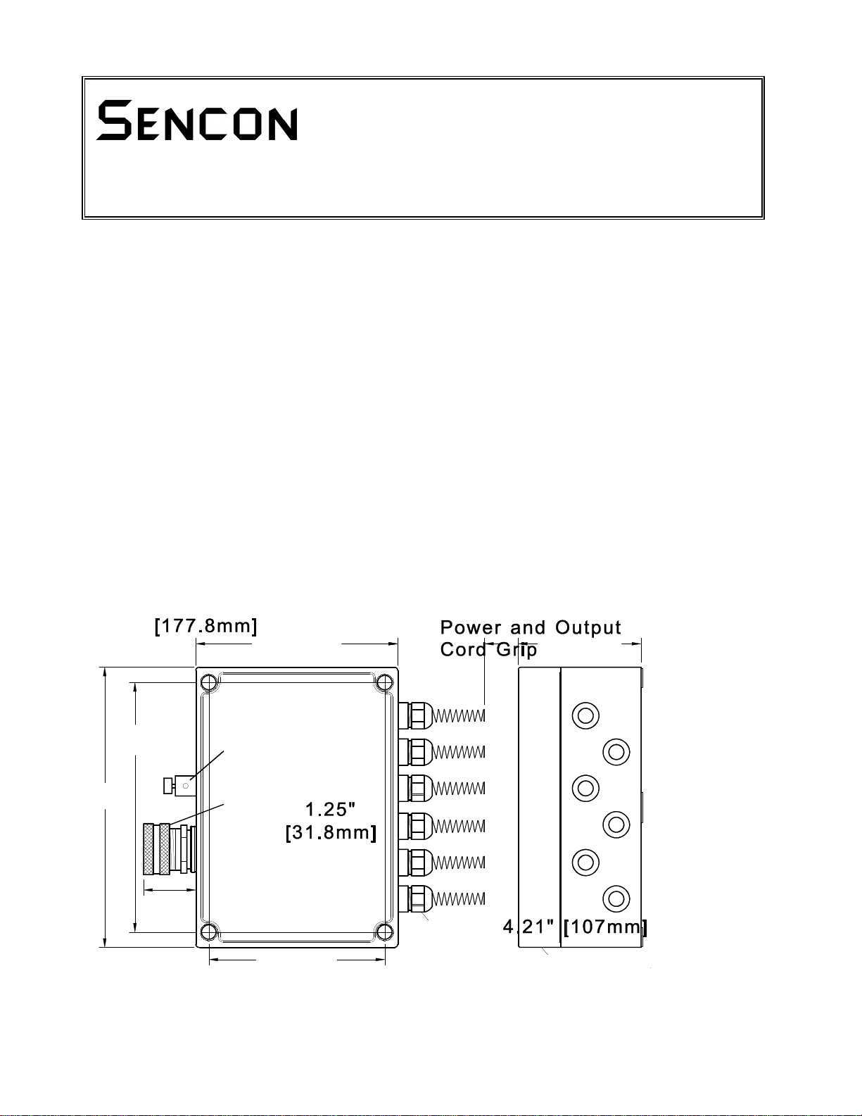
The SIP-6 housing is a tough polycarbonate NEMA 4X enclosure with a clear cover for viewing the LEDs and
adjustment potentiometers located inside. The basic box measures 7 inches [178 mm] high by 5 inches [127
mm] wide by 3 inches [76 mm] deep. Six cord grips with watertight gland fittings and integral strain relief are
located on the right-hand side of the box. Sensor cables enterthe box through these fittings. Thewires terminate
on individualplug-in connectors as shown in the drawings. Power and output signal wiring enter the box through
a larger cord grip and connector on the left-hand side of the box. The cord grip for the output cable works with
cable diameters of 0.375 inches [9.5 mm] to 0.500 inches [12.7 mm]. When using a jacketed cable in thisrange,
the SIP-6 is drip-proof. Change the cord grip when using a larger or smaller diameter cable to maintainthewater
tight seal (cord grips in any desired size range are readily available at an electrical supply house).
DIMENSIONS AND MOUNTING

2
SPECIFICATIONS
Input Voltage
12 to 30 Volts DC
Input Current
60 mA Maximum with All LEDs On (Plus Sensor and Load Current)
Short Circuit
Protected
Protected
Reverse
Polarity
Protected
Isolation
250 Volts
EMI
Protected
Storage
Temperature
- 40EF to +176EF [- 40EC to +80EC]
Operating
Temperature
+32EF to +140EF [0EC to +60EC]
Environment
The box is gasketed and sealed similar to NEMA 4X or IP65. The
watertight integrity of the box depends on the proper selection and
use of the power and output cable and its cord grip.
GENERAL CHARACTERISTICS
Weight
30 oz. [850 grams]
Material
Polycarbonate
Termination
5 and 12 position "Touch Safe" terminal blocks, suitable for
22 AWG [0.32 mm
2
] to 12 AWG [3.3 mm
2
] wire sizes.
3
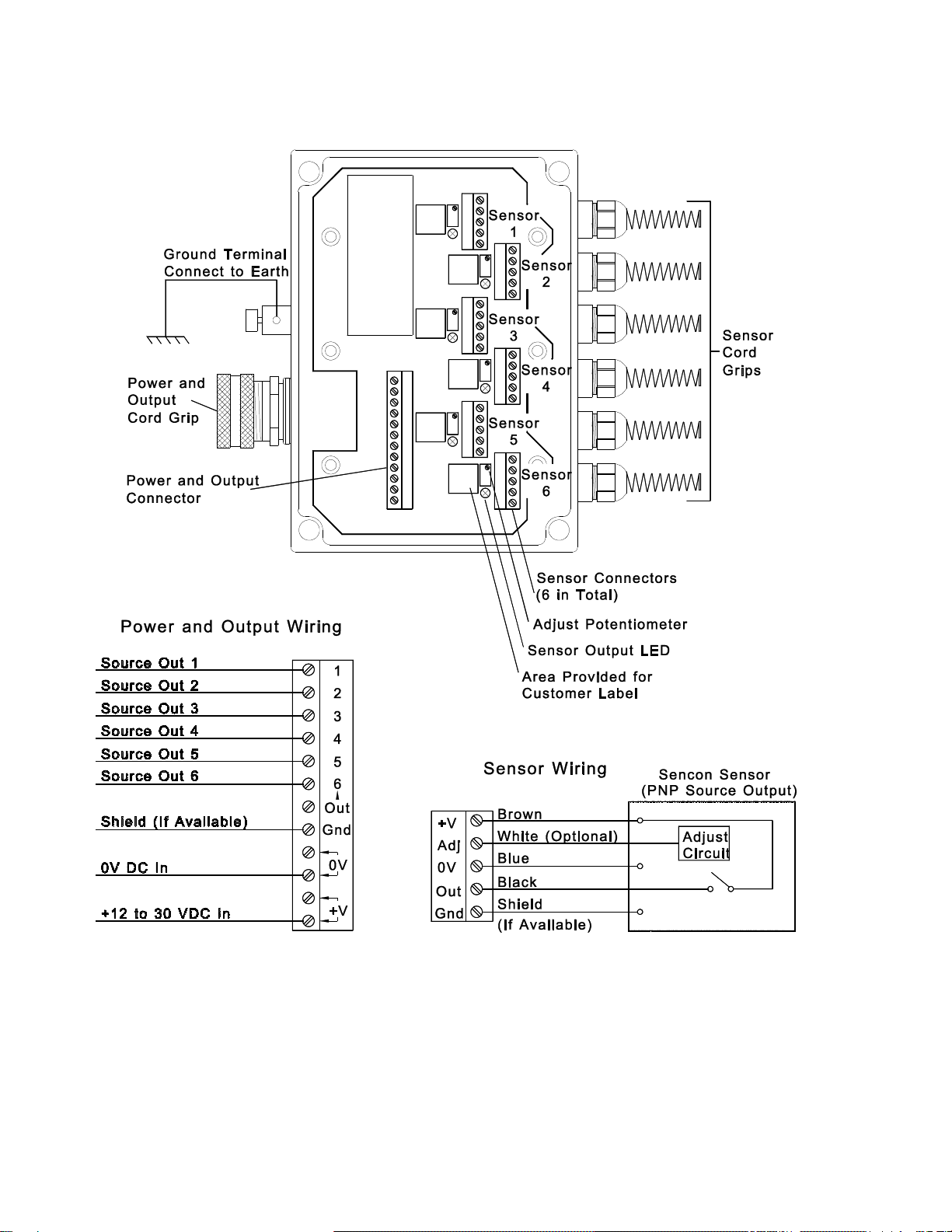
INTERCONNECTION

4
SETUP AND USE
Install the SIP-6 in a convenient location within reach of the sensors. With the cover removed, pass the endof the
sensor cable through the spiral cord grip and into the SIP-6. Do not tighten the cord grip down yet. Pull enough
cable through to simplify working on the wires. Strip back the outer jacket for a distance of about 1 inch [25 mm]
and separate the wires. Strip one-quarter inch [6 mm] of insulation off the end of each wire. Lift the five pin
connector out of its socket on the board and wire the cable to the connector as shown in the interconnection
drawing. Now grasp the cable outside the box and pull it back out of the SIP-6 until the five pin connector can plug
into its socket and the wires are dressed neatly over to the fitting. Tighten the cord grip now, but do not go
overboard with the amount of force applied. Tighten the cord gripusingonlymoderateforce. Repeatthis procedure
with the other five sensors. There is a 0.5" [13 mm] square blank area on the circuit board next to each connector
for the user to attach a sensor ID label.
Now bring the power and output cable into the SIP-6 through the cord grip on the opposite side of the box. Strip
back the outer jacket and insulation on the wires as described above. Lift the 12pin connector out of its socket on
the board and wire the cable to the connector as shown in the interconnection drawing. Dress the cable back out
through the cord grip and plug the connector into the board. Tighten the cord grip just enoughtograbthe cableand
act as a seal.
Bring a wire from the machine frame to the ground terminal on the outside the SIP-6 just above the power cable.
Strip back the insulation and insert the wire into the hole in the terminal. Tighten the black thumb-nut to hold the
wire.
Apply power to the SIP-6 and verify that all of the sensors are working by observing the red LED located next to
each sensor connector. Also, check for the proper signals on the power/output connector. If the on-off operating
point for a sensor is not satisfactory, and it has the optional remote adjustment feature, then turn the adjustment
potentiometer for that sensor to obtain the desired setup. An adjustment tool is supplied with each SIP-6 to help
installation. Turning the potentiometer clockwise increases the range of the sensor. Turning it counterclockwise
decreases the sensor range. Note that the SIP-6 only slightly adjusts the operating point of the sensor. It cannot
compensate for improper installation of your sensors. Follow the setup instructions that accompany the sensors
before trying to adjust their operation via the SIP-6. Failure to follow these guidelines mayresult in marginal sensor
operation.
Note: To return the SIP-6 to the factory settings follow these steps.
1. Place a DC voltmeter between the "ADJUST" terminal (positive meter lead) and "0V" terminal
(negative meter lead) on the five pin sensor connector.
2. Turn the potentiometer until the adjust voltage equals +3 VDC. This is the neutral setting.
3. Adjust the sensor location as needed to obtain proper operation.
Replace the cover on the SIP-6. The installation is now complete.

5
ORDERING INFORMATION
For more detailed specifications, price quotes, or applications information, contact your SENCON sales office listed below:
NORTH, CENTRAL & SOUTH AMERICA
Sencon Incorporated
6385 W.74th Street
Bedford Park, IL 60638
USA
Tel: +1 708 496 3100
Fax: +1 708 496 3105
EUROPE - MIDDLE EAST - ASIA
Sencon (UK) Ltd
Stonebridge Cross Business Park
Droitwich WR9 0LW
UK
Tel: +44 1905 827800
Fax: +44 1905 795876
www.sencon.com
PUBLISHED 11 July 1994 TECHNICAL DATA SHEET# 096-41371-00
Please Note: Due to product improvement, specifications are subject to change without notice.
Table of contents
Popular Recording Equipment manuals by other brands


Ramix
Ramix PMC551 Hardware Reference and Installation Manual

DEVA Broadcast
DEVA Broadcast DEVA DB8000 Maintenance and operation instruction manual

Digitimer
Digitimer D400 Operator's manual

KEYBOARDPARTNER
KEYBOARDPARTNER HX3.5 WiFi Module Update manual

L-Acoustics
L-Acoustics LA4X owner's manual

Future light
Future light ICL-6 user manual


