- 2 - TroveIR Installation Guide
Overview:
Trove2IR2 and Trove3IR3 accommodate various combinations of Inner Range boards with or without Altronix power supplies and accessories for
access systems.
Agency Listings:
• UL 294 - 6th edition: Line Security I, Destructive Attack I, Endurance IV, Stand-by Power II*. *Stand-by Power Level I if no battery is supplied.
• This Class B digital apparatus complies with Canadian ICES-003.
Cet appareil numérique de la classe B est conforme á la norme NMB-003 du Canada.
• CE European Conformity.
Specifications:
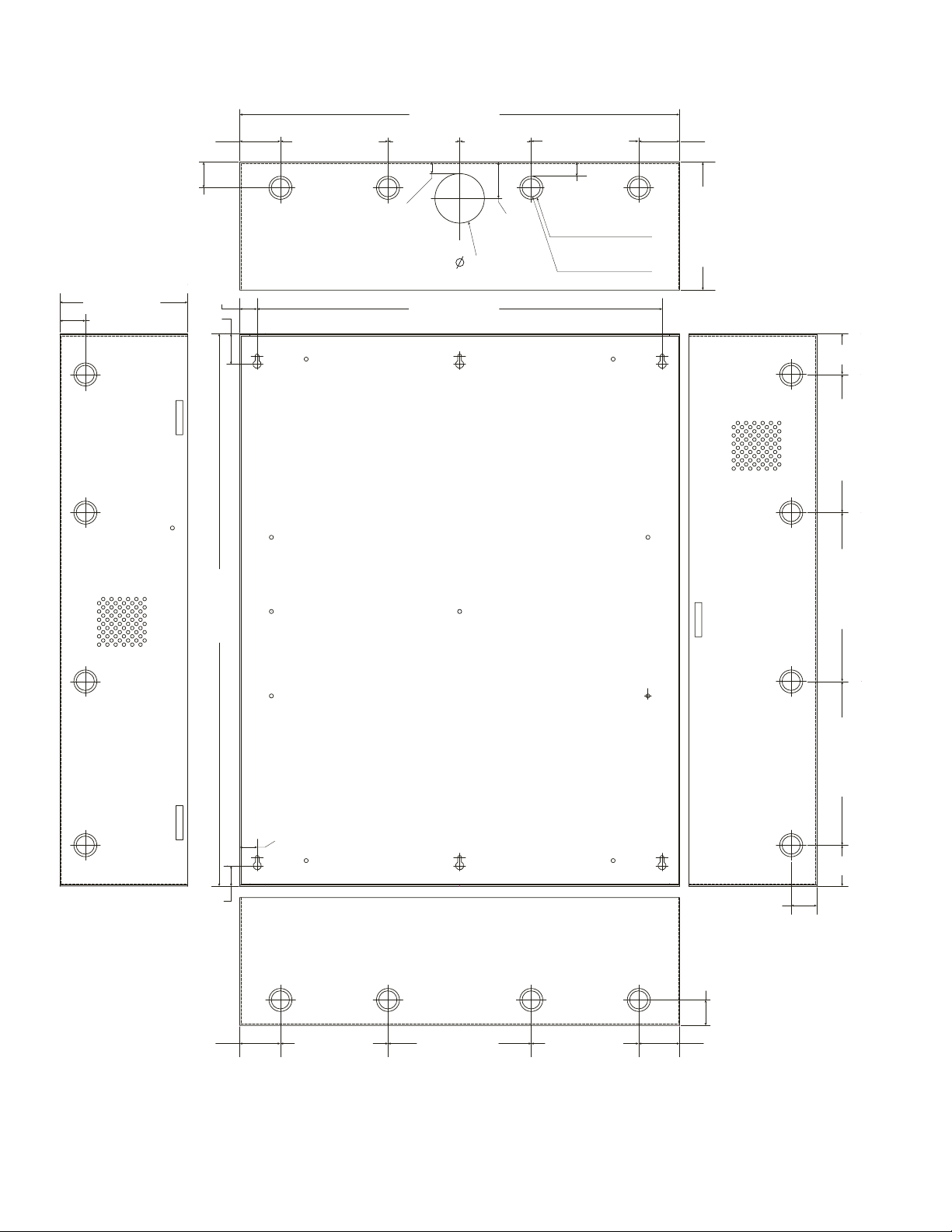
Trove2IR2
Trove2 enclosure with TIR2 Altronix/Inner Range backplane.
• Includes: tamper switch, cam lock, mounting hardware.
• 16 Gauge enclosure with ample knockouts for convenient access.
Enclosure Dimensions (H x W x D): 27.25” x 21.75” x 6.5” (692.2mm x 552.5mm x 165.1mm).
Accommodates up to four (4) 12VDC/7AH batteries.
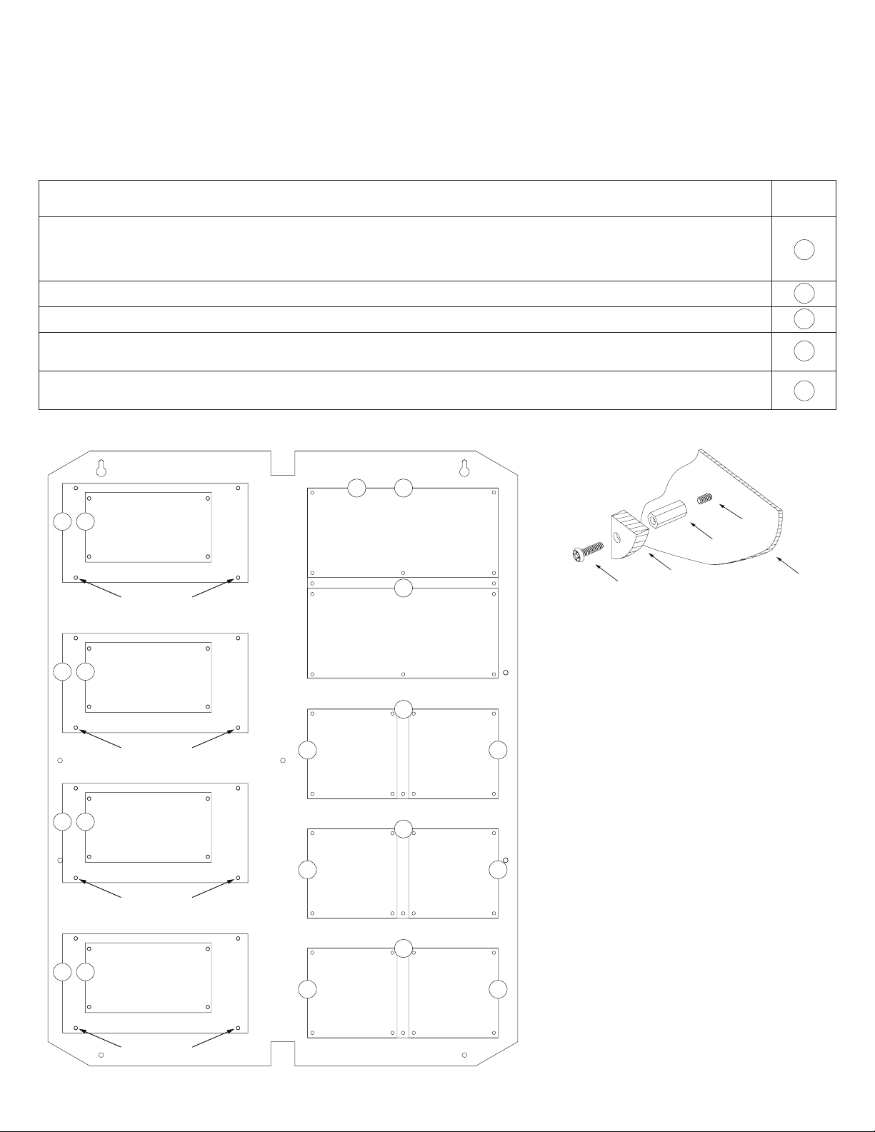
TIR2
Altronix/Inner Range backplane.
• 16 Gauge backplane.
• Includes mounting hardware.
Dimensions (H x W x D): 25.375” x 19.375” x 0.3125” (644.6mm x 492.1mm x 7.9mm).
TIR2 accommodates a combination of the following:
Altronix:
• Up to four (4) AL400ULXB2, AL400ULXB2V, AL600ULXB, AL600XB220, AL1012ULXB, AL1012XB220, AL1024ULXB2, AL1024XB2V,
eFlow4NB, eFlow4NBV, eFlow6NB, eFlow6NBV, eFlow102NB, eFlow102NBV, eFlow104NB, eFlow104NBV, PoE60, PoE201, Tango1B,
ACM8, ACM8CB, ACMS8, ACMS8CB, LINQ8ACM, LINQ8ACMCB.
• Up to four (4) ACM4(CB), MOM5, PD4UL(CB), PD8UL(CB), PDS8(CB), or VR6.
Inner Range:
• One (1) Integriti Security Controller INTG-996001EUPCBK or Integriti Access Controller module INTG-996035PCBK.
• Up to five (5) Integriti 8-32 Zone LAN I/O Expander modules INTG-996005PCBKIT or Integriti Intelligent LAN Access modules INTG-996018PCBK
or Integriti Standard LAN Access modules INTG-996535PCBK or Integriti UniBus 16 Floor Lift Interface Device INTG-996540PCBK.
• Up to six (6) Integriti Standard LAN Access Module PCB INTG-996012PCBK or ntegriti UniBus 8 Zone Expansion Device INTG-996500PCBKIT
or Integriti UniBus 8 Relay Expander INTG-996515PCBKIT or Integriti Unibus 8 Auxiliary Relay Expander INTG-996520PCBKIT
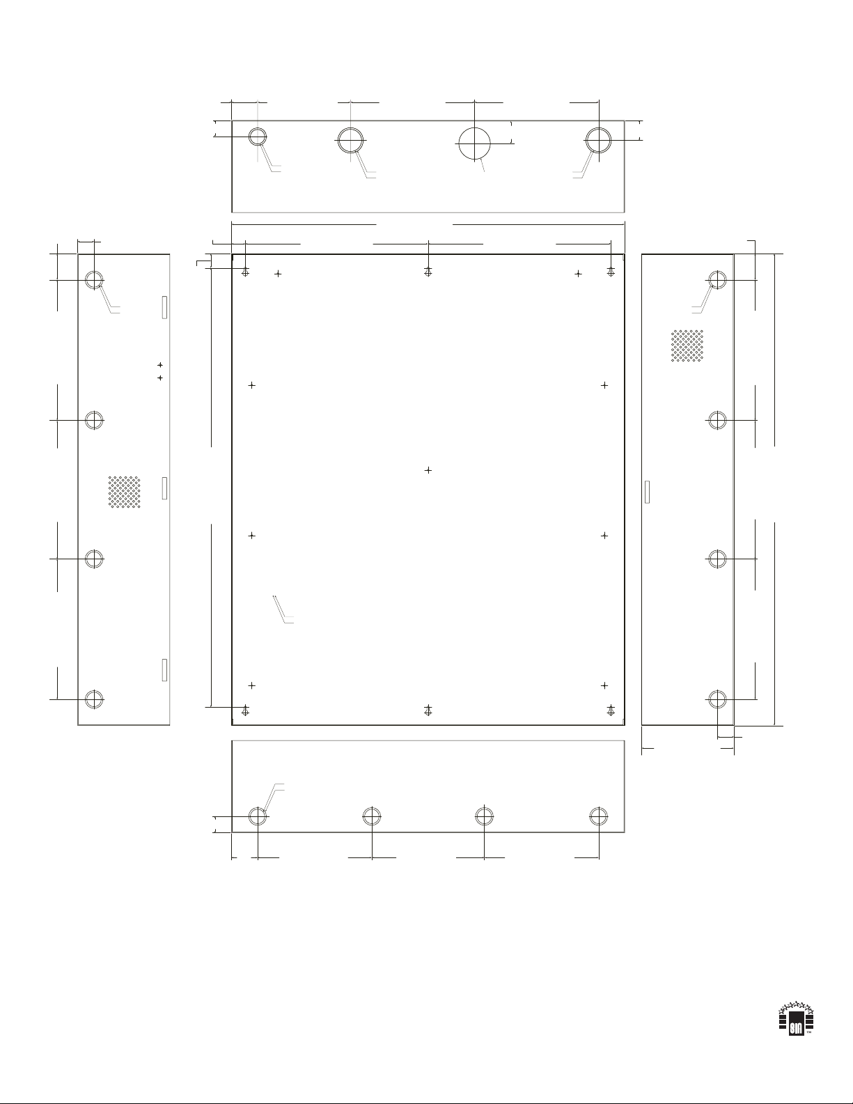
Trove3IR3
Trove3 enclosure with TIR3 Altronix/Inner Range backplane.
• Includes: two (2) tamper switches, cam lock, mounting hardware.
• 16 Gauge enclosure with ample knockouts for convenient access.
Enclosure Dimensions (H x W x D): 36.12” x 30.125” x 7.06” (917.5mm x 768.1mm x 179.3mm).
Accommodates up to four (4) 12VDC/12AH batteries.
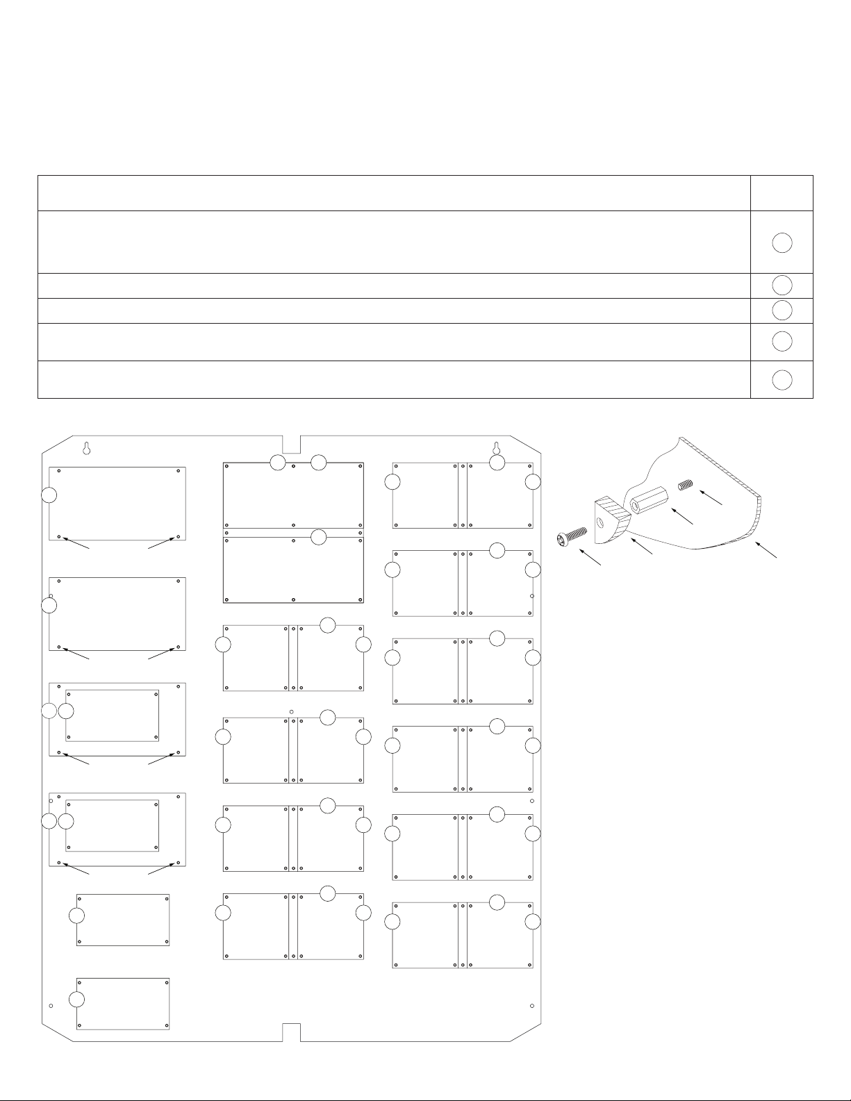
TIR3
Altronix/Inner Range backplane.
• 16 Gauge backplane.
• Includes mounting hardware.
Dimensions (H x W x D): 34” x 28” x 0.3125” (863.6mm x 711.2mm x 7.9mm).
TIR3 accommodates a combination of the following:
Altronix:
• Up to four (4) AL400ULXB2, AL400ULXB2V, AL600ULXB, AL600XB220, AL1012ULXB, AL1012XB220, AL1024ULXB2, AL1024XB2V,
eFlow4NB, eFlow4NBV, eFlow6NB, eFlow6NBV, eFlow102NB, eFlow102NBV, eFlow104NB, eFlow104NBV, PoE60, PoE201, Tango1B,
ACM8, ACM8CB, ACMS8, ACMS8CB, LINQ8ACM, LINQ8ACMCB.
• Up to four (4) ACM4(CB), MOM5, PD4UL(CB), PD8UL(CB), PDS8(CB), or VR6.
Inner Range:
• One (1) Integriti Security Controller INTG-996001EUPCBK or Integriti Access Controller module INTG-996035PCBK.
• Up to twelve (12) Integriti 8-32 Zone LAN I/O Expander modules INTG-996005PCBKIT or
Integriti Intelligent LAN Access modules INTG-996018PCBK or Integriti Standard LAN Access modules INTG-996535PCBK or
Integriti UniBus 16 Floor Lift Interface Device INTG-996540PCBK.
• Up to twenty (20) Integriti Standard LAN Access Module PCB INTG-996012PCBK or ntegriti UniBus 8 Zone Expansion Device INTG-996500PCBKIT
or Integriti UniBus 8 Relay Expander INTG-996515PCBKIT or Integriti Unibus 8 Auxiliary Relay Expander INTG-996520PCBKIT.