Sencon SI9000 plus User manual

SI9000
plus
Enamel Rater
User Manual
REF
OPERATION
MANUAL No.
092-00900-10
LANGUAGE
ENGLISH
REVISION
10

2ENAMEL RATER MANUAL: V.10

ENAMEL RATER MANUAL: V.10 3
1. INTRODUCTION 5
1.1 THE ENAMEL RATING TEST 5
1.2 THE SI9000+ 5
1.2.1 BODY CONTACT AND LEVEL CHECKING 6
1.2.2 SEMI-AUTOMATIC OPERATION 6
1.2.3 BATCH OPERATION 6
1.2.4 CONSTRUCTION 6
1.3 THE SI9005 CAN STAND 7
2. GETTING STARTED WITH YOUR SI9000+ 8
2.1 SAFETY 8
2.2 SETTING THE MAINS VOLTAGE 8
2.3 ADJUSTING AND CONNECTING THE CAN STAND 10
2.4 CONNECTING ANON-SENCON PROBE 12
2.5 SWITCHING ON AND THE SELF TEST 13
3. OPERATION 14
3.1 GENERAL DESCRIPTION 14
3.2 CONFIGURATION CHECK 14
3.3 FREE RUN AND REVERSE POLARITY15
3.4 BATCH MODE 16
3.4.1 RATING CANS 16
3.5 MASTER RESET 17
3.6 ERROR MESSAGES 18
4. CONFIGURING YOUR SI9000 19
4.1 SETTING THE MAINS VOLTAGE 20
4.2 SETTING UP THE STATISTICAL OUTPUT 21
4.3 THE LEVEL INTERLOCK 21
4.4 THE CONTACT INTERLOCK 22
4.5 CHANGING THE RATING VOLTAGE 22
4.6 CHANGING THE RATING DURATION 22
4.7 AUTORANGING OPERATION 23
4.8 LINE NUMBER ENABLE 23
4.9 AUTOSTART 24
4.10 AUTOSAVE 24
5. MAINTENANCE AND SERVICING 25
5.1 CARE OF YOUR SI9000+ 25
5.2 ROUTINE MAINTENANCE 25
5.3 ROUTINE TESTING 25
5.5 FAULT FINDING 27
5.6 REPLACING THE FUSE 28
5.7 OBTAINING HELP FROM SENCON 28
6. USING THE SI9000+ WITH A PRINTER 29
6.1 OVERVIEW 29
6.2 CHOOSING APRINTER 29
6.3 CONNECTING THE PRINTER 30
6.3.1 THE EPSON FX OR EX PRINTER 30
6.3.2 THE TANDY DMP132 PRINTER 31
6.3.3 USING OTHER PRINTERS 31
6.4 SETTING UP THE RS232 DATA FORMAT 32
6.4.1 SETTING UP THE EPSON PRINTER 32
6.4.2 SETTING UP THE TANDY PRINTER 33

4ENAMEL RATER MANUAL: V.10
6.4.3 SETTING UP OTHER PRINTERS 33
6.5 ENABLING THE PRINTOUT 33
6.6 SELECTING THE PRINTOUT FORMAT 34
6.7 PRINTER PROBLEMS 35
7. USING THE SI9000+ WITH A COMPUTER 36
7.1 GENERAL 36
7.2 COMPUTER PORT CONNECTIONS 36
7.3 SETTING DATA FORMAT AND SPEED 37
7.4 UNI-DIRECTIONAL PROTOCOL 38
7.5 BI-DIRECTIONAL PROTOCOL 38
7.6 FORMAT OF MESSAGE TRANSMITTED 39
7.7 ERROR MESSAGES 39

ENAMEL RATER MANUAL: V.10 5
1. INTRODUCTION
1.1 THE ENAMEL RATING TEST
The can industry has established a standard test for lacquer
integrity of food and beverage cans. The test involves applying a
voltage between a conductive liquid (electrolyte) within the can and
the metallic can body. As the internal lacquer coating is an
insulator, any current which flows is an indication of imperfections
in the lacquer . The larger the current the greater the area of the
imperfections and the poorer the quality of the can.
There is no definitive standard for the enamel rating test. Different
users have their own standards specifying the test voltage and test
duration, however a common standard requires a voltage of 6.3V to
be supplied for 4 seconds. In its factory supplied configuration the
SI9000+ uses this voltage and duration.
When a faulty can is detected the normal procedure is to reverse
the polarity of the applied voltage, which causes bubbles of gas to
be released from the area of the fault. This gives a visual indication
of the location of the fault and enables corrective action to be
taken.
1.2 THE SI9000+
The following description of operation assumes that the SI9000+ is
operated in its factory set configuration (see Appendix A Fig 1 for
settings).

6ENAMEL RATER MANUAL: V.10
1.2.1 BODY CONTACT AND LEVEL CHECKING
One of the problems the enamel rating test has suffered in the past
is that if any part of the circuit has a poor, high resistance contact
only a small current will flow and the instrument will show a bad can
as good. This is a particular problem where electrical contact is
made with the can body.
In order to overcome this problem the SI9000+ has special circuitry
which checks the contact with the can body and will not allow the
test to proceed until a good contact has been detected. In addition
to this, a similar circuit checks that the electrolyte level within the
can is adequate and so avoids the problem of the upper zone of
the can not being fully tested due to insufficient electrolyte. These
two circuits together will also detect a fault anywhere in the
connector or wiring to the probe, making the SI9000+ fail-safe in its
operation.
1.2.2 SEMI-AUTOMATIC OPERATION
Another spin-off of these check-circuits is that the SI9000+ can be
configured to detect a change of can and will automatically start the
test once a new can is correctly inserted. An internal timer will
freeze the reading when a preset time (e.g. 4 seconds) has elapsed
and one key press then prepares the instrument for the next can.
1.2.3 BATCH OPERATION
As the operator rates cans the SI9000+ will store the readings (up
to 99) in its memory as a batch. At any time during the batch
statistical information about the batch can be displayed and at the
end of the batch the readings in tabular format together with the
statistical information can be output to a printer or computer if
required.
1.2.4 CONSTRUCTION
The acrylic coated steel case and waterproof polyester facia panel
are designed to ensure that the SI9000+ will withstand the rigours
of a factory environment. Further to this the case, mains-switch
and connectors are all sealed to I.P.65 rating, thus preventing any
ingress of corrosive electrolytes and allowing operation of the
SI9000+ in "hose-down" areas.

ENAMEL RATER MANUAL: V.10 7
1.3 THE SI9005 CAN STAND
Due to the corrosive nature of the electrolytes used in enamel
rating the life of probe attachments can be very poor. With this in
mind, the SI9005 has been designed using nylon parts wherever
possible, whilst all metal parts are made from specially selected
stainless steels, heat treated where appropriate. The wiring of the
can stand is completely sealed against corrosion from electrolytes
which not only improves the life but ensures accuracy and reliability
of the readings taken.
Electrical contact is made with the can by three hardened knife
edges, one of which is wired separately to allow electrical contact
checking, and the two probes (one for rating and a shorter probe
for level checking) are supported on an adjustable arm and
telescopic column. This arrangement allows the probes to be lifted
and rotated to one side while the can is being inserted.

8ENAMEL RATER MANUAL: V.10
2. GETTING STARTED WITH YOUR SI9000+
2.1 SAFETY
The test voltages used by the SI9000+ are sufficiently low so as to
present no hazard whatsoever under all circumstances. Although
potentially dangerous mains voltages are present inside the unit,
the construction of the case to I.P.65 rating will prevent any hazard
from this whilst the case remains intact. Should the facia become
perforated or the case become damaged in such a way as to
destroy the seal then the unit must be removed from service
immediately and returned to Sencon for repair. Operators should
be warned to keep electrolytes away from electrical socket outlets
and never handle plugs with wet hands.
2.2 SETTING THE MAINS VOLTAGE
The mains voltage of the SI9000+ is factory set as appropriate for
the particular country to which it is supplied and the setting will be
clearly marked on the back panel. Should you need to change the
voltage proceed as follows:-
i. Remove the six button head screws in the base of the
case using the 2.5mm hex wrench supplied.
ii. Remove the base panel taking care not to damage the
earthing cable.
iii. Referring to Appendix A Fig 1 move the mains voltage
switch to the required position.
iv. Check that the foam seal on the bottom of the case is
intact and replace the base panel and six screws.
v. Change or remove the voltage label.

ENAMEL RATER MANUAL: V.10 9
Key to Enamel Rater Probe
1 -
Bushing
7 -
Body Contact
2 -
Foot
8 -
Locating Ring
3 -
Clamp Screw
9 -
Probe Arm
4 -
Locking Screw
10 -
Inner Column
-
Level Probe
11 -
Outer Column
6 -
Main Probe
12 -
Stand Base
FIGURE 2: ENAMEL RATER PROBE

10 ENAMEL RATER MANUAL: V.10
2.3 ADJUSTING AND CONNECTING THE CAN STAND
In order to make use of the electrolyte level checking facilities of
the SI9000+, it is important that the can stand is adjusted correctly
for the height of can to be tested. Referring to Fig.2 proceed as
follows:-
i. Raise outer column (item 11) and place can through the
can locating ring (item 8) onto the body contacts (item 7).
ii. Lower the outer column.
Note If at any time the outer column will not return to
its normal position resting on the stand base
(item 12) due to the cable fouling inside, then
raise the outer column and rotate clockwise for
several turns until the column moves freely
again.
iii. Slacken clamp screw (item 3) using the 3mm hex wrench
supplied, and slide the probe arm (item 9) so that the
bottom of the level probe (item 5) is at the minimum
permissible electrolyte level and the outer column is firmly
against the stand base.
iv. Tighten the clamp screw making sure the main probe
(item 6) is central in the can. Take care not to overtighten
the clamp screw as this will cause the outer column to
bind on the inner column.
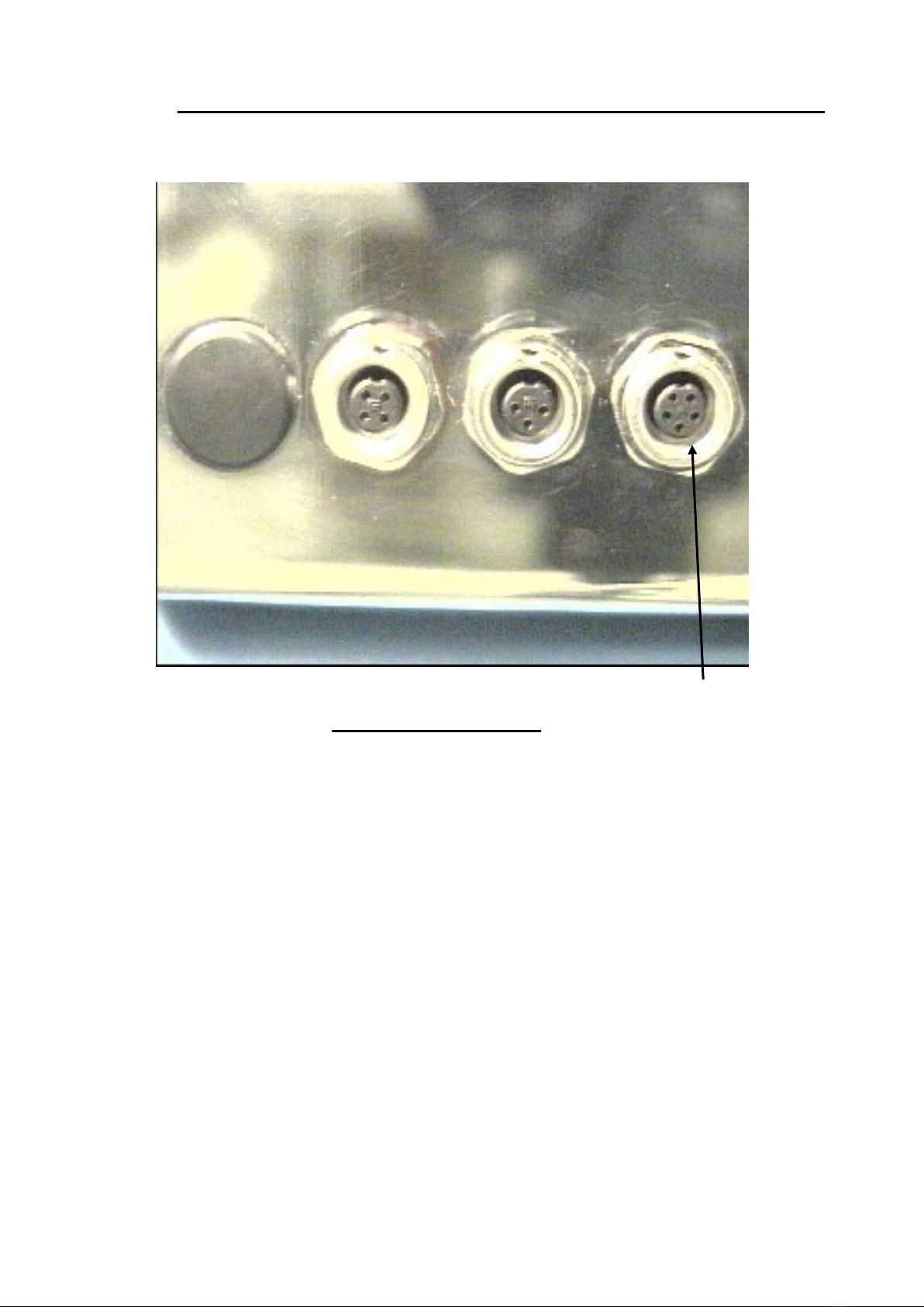
The can stand is now ready for use and should be connected to the
SI9000+ via the probe socket (refer to Fig.3). This connector is
polarised so it must be aligned before insertion. Always screw in
the locking ring and tighten finger-tight to ensure it is sealed against
electrolyte.
ENAMEL RATER MANUAL: V.10 11
FIGURE 3: SIDE PANEL
CAN PROBE
CONNECTOR

12 ENAMEL RATER MANUAL: V.10
2.4 CONNECTING A NON-SENCON PROBE
If you want to connect another probe to your SI9000+ for
specialised tests such as end, or side-seam enamel rating this is
always possible using the 5 pin plug supplied, but the following
points should be noted:-
i. The cable diameter must be in the range 3mm to 5mm to
ensure correct sealing.
ii. Other probes are unlikely to support body contact and
level checking and so these functions will be disabled.
iii. If (ii) above applies, then the automatic restart facility after
each can will be disabled.
Soldering of the cable should be carried out by an electrician as
follows:-
Pin Function
1 Main probe (electrolyte connection).
2 Level probe (if not used, connect to 1).
3 Body contact check (if not used connect to
4).
4 End or can body contacts.
5 Not connected.
The probe can now be connected to the SI9000+ via the probe
socket (refer to Fig.3). Ensure the connector is aligned before
insertion and screw in the locking ring finger-tight to ensure a good
seal.

ENAMEL RATER MANUAL: V.10 13
2.5 SWITCHING ON AND THE SELF TEST
Having satisfied yourself that the mains voltage setting is correct,
connect the mains plug to a suitable socket outlet or if you prefer
wire the mains cable directly into a fused outlet. Switch on the
SI9000+ by depressing the mains on/off switch on the back panel.
On power up, the system will perform a self-test. The numeric
displays will cycle through each digit from 0 through to 9 allowing
the operator to see that all the segments illuminate correctly. The
LED indicators will be illuminated in sequence.
Finally the SI9000+ will go to standby mode with the can number
and timer set to zero and the milliamp display set to dashes.
Enamel rating can then begin by pressing.
i. The start key. Enamel rating will start when the level and
contact check requirements are satisfied (indicators off)
and continue for 4 seconds.
ii. The Free Run key. The SI9000+ will enamel rate for up
to 99 seconds in free run.
iii. The Reverse Polarity key. As ii) but with reversed
polarity (can body negative)

14 ENAMEL RATER MANUAL: V.10
3. OPERATION
3.1 GENERAL DESCRIPTION
The SI9000+ will operate in two basic modes, "free run" and
"batch".
The free run mode includes reverse polarity operation, and is a
totally manual operation not using any of the automatic features or
interlocks of the SI9000+. Although it can be used as an operating
mode on its own it is also available from within batch mode.
The normal operating mode is batch mode and this should be used
for rating cans even if a batch is not being tested.
All instructions assume the SI9000+ is initially in standby mode, i.e.
the milliamp display shows dashes and set to the factory
configuration given in Appendix A Fig 1.
3.2 CONFIGURATION CHECK
The Rating voltage and rating duration can be inspected whilst the
SI9000+ is in standby mode (i.e. the milliamp display shows
dashes) and before or after rating. To examine the rating voltage
and rating duration:
i. Press the set key. The rating voltage is displayed on the
milliamp display. The ↑and ↓key are ignored.
ii. Press the set key again. The rating duration is displayed
on the timer display. The ↑and ↓keys are ignored.
iii. Press the End key. The SI9000+ drops back to the
condition it was in before the configuration check was
made.

ENAMEL RATER MANUAL: V.10 15
3.3 FREE RUN AND REVERSE POLARITY
i. Place a can in the can stand, fill with electrolyte and lower
the probe.
ii. Press FREE RUN.
The rating indicator will light, the timer display will
increment and the current will be displayed in milliamps.
The check circuits will be active but will not prevent
operation. If either of the red warning indicators is lit then
more electrolyte should be added or the can should be
rotated against the body contacts as necessary.
iii. To freeze the reading at any point press FREE RUN.
Rating will stop and the timer will be halted. Rating can
be resumed by pressing FREE RUN once more.
iv. To reverse the polarity press REVERSE POLARITY.
Note that the contact and level check circuits are disabled
when reverse polarity is selected.
v. To return to normal polarity, press FREE RUN.
vi. To return to standby mode, press END.
Reverse polarity operation is similar, but press REVERSE
POLARITY instead of FREE RUN.
If the timer should reach 100 seconds, the mode will be cleared
automatically and the SI9000+ will revert to standby mode.
Free run and reverse polarity are available from within batch mode
and operate as described above except that pressing END or the
timer reaching 100 seconds will return the SI9000+ to the stage
from where free run or reverse polarity had been selected.

16 ENAMEL RATER MANUAL: V.10
3.4 BATCH MODE
3.4.1 RATING CANS
i. Place a can in the can stand, fill with electrolyte and lower
the probe.
If the body contact and level checks are clear, the can number will
change to 1 and rating will commence. If either of the red warning
indicators are lit then more electrolyte must be added or the can
should be rotated against the body contacts as necessary.
After the preset time has elapsed (usually four seconds), rating will
stop and the reading will be frozen. The operator has the following
options:-
i. Save the reading in the internal memory by pressing
SAVE.
ii. Abandon the reading by pressing CLEAR.
iii. Enter free run mode by pressing FREE RUN.
iv. Enter reverse polarity mode by pressing REVERSE
POLARITY.
v. View the set rating time and rating voltage by pressing
SET.
If options iii or iv are chosen, operation will be as described in
section 3.3. Remember that if END is pressed, or timeout occurs,
the original timed reading will be redisplayed and the operator must
press SAVE or CLEAR to continue.
Having pressed SAVE or CLEAR the SI9000+ will be waiting for a
new can and it will use its check circuits to detect the can being
changed. Free run and reverse polarity are available at this point.
To test the next can proceed as follows:-
i. Remove the can just tested.
ii. Insert a new can, fill with electrolyte, and lower the probe.
If the SI9005 can stand is being used, the SI9000+ will detect the
new can and as soon as both checks are clear will start rating the
new can. If another probe that does not support body contact and
level checks is being used, then press START to tell the SI9000+ it
has a new can.
By repeating the above operations up to 99 cans can be tested and
their results stored. When 99 readings have been stored a "batch
end" is automatically invoked.

ENAMEL RATER MANUAL: V.10 17
3.5 MASTER RESET
In the event of a major change, error or fault it may become
necessary to completely reset the instrument. This is always
required when the operating mode is changed.
A reset will erase all stored settings and reading from the units
memory.
To perform a master reset proceed as follows;
A) Switch off power to the unit.
B) Simultaneously hold down the SET, ↑and ↓
keys.
C) Switch on the power.
D) After 2 seconds release the keys and the
system will be reset.
When a master reset is performed the operator has the opportunity
to change the default times and voltage settings (factory set to 4
seconds and 6.3V) using the SET, ↑and ↓keys. The new default
values are stored in battery backed memory and are retained until
another master reset is performed. The rating voltage and duration
can be checked during operation as described in Section 3.2.

18 ENAMEL RATER MANUAL: V.10
3.6 ERROR MESSAGES
"OL" The SI9000+ has tripped out on current
overload. Remove the cause of the overload
and press CLEAR.
"ERR" The Err message is displayed if the Batch/Stats
key is depressed before any readings have been
taken. Under these conditions it is not possible
to calculate statistical information and there is
no information available to send to a printer.
"FAIL" This message may flash on power up and
indicates that battery back-up of memory has
failed. A master reset should be performed (see
section 3.5). The clear key can be pressed to
continue operation, but the chance that
previously saved readings are corrupted is very
high.
"BUSY" The SI9000+ is waiting for the printer (see
Section 6.7).
"BUFFER Scrolling, computer buffer is 90% full
NEARLY FULL" (see Section 7.7).
"FULL" Flashing, computer buffer is full (see Section
7.7).
"PSU" The power supply generating the rating voltage
has failed. The SI9000+ may reset when
CLEAR or END is pressed, alternatively switch
off the SI9000+ for a few seconds.
"CLR?" If BATCH/STATS is pressed when no printer is
connected and the statistical output is disabled
(see section 4.2) the CLR? message is
displayed. Press CLEAR to clear the memory or
END to return to the condition before
BATCH/STATS was pressed.
"PR ?" BATCH/STATS has been pressed when the
statistical output is off (see section 4.2). The
raw data may be printed by pressing SAVE.

ENAMEL RATER MANUAL: V.10 19
4. CONFIGURING YOUR SI9000+
In order to change the configuration of the SI9000+ it is necessary
to remove the base panel. Instructions for doing this are given in
section 4.1 (i) and (ii). Before changing the configuration of the
SI9000+ it is recommended that users familiarise themselves with
the internal layout shown in Appendix A Figure 1. A list of the
switches and jumpers of interest follows:
SWITCH/
JUMPER
NAME
LOCATION
TYPE
OPERATION
SW1
Micro board (Top
Board) To right of
SW2
Block of 8 miniature
rocker switches
numbered 1 to 8 on the
device
A switch is off when its rocker
is pressed down adjacent to
the "open" legend.
SW2
Micro board (Top
Board) To left of SW1
Block of miniature rocker
switches numbered 1 to 8
on the device
A switch is off when its rocker
is pressed down adjacent to
the "open" legend.
SW11
Applications board
(Lower Board) Below
Fuses
Block of miniature rocker
switches numbered 1 to 8
on the device
A switch is off when its rocker
is pressed down adjacent to
the "open" legend.
Mains
Selector
Switch
Applications board
(Lower Board) To the
right of the fuses
Slide Switch
Slide to correct position for
supply voltage.
J1
Micro board (Upper
Board) R.H.S.
3 position jumper
Connect the pair of pins
adjacent to the required
legend A,B or C using the
jumper.
J2
Micro board (Upper
Board)
2 position jumper
Connect the upper pair of pins
for A or the lower pair for B,
using the jumper.

20 ENAMEL RATER MANUAL: V.10
SWITCH/
JUMPER
NAME
LOCATION
TYPE
OPERATION
J3
Micro board (Upper
Board)
2 position jumper
Connect the left hand pair
of pins for A or the right
hand pair for B, using the
jumper.
VR1
VR5
Applications board (Lower
board) below the
transformer
Multiturn Pot
Adjust in accordance with
Section 5.4.1.
VR6
VR7
Applications board (Lower
board) to the right of the
transformer
Multiturn Pot
Adjust in accordance with
Section 5.4.2.
The factory settings for the jumpers and switches are shown in Appendix A Fig 1.
4.1 SETTING THE MAINS VOLTAGE
The mains voltage of the SI9000+ is factory set as appropriate for
the particular country to which it is supplied and the setting will be
clearly marked on the back panel. Should you need to change the
voltage proceed as follows:-
i. Remove the six button head screws in the base of the
case using the 2.5mm hex wrench supplied.
ii. Remove the base panel taking care not to damage the
earthing cable.
iii. Referring to Appendix A Fig 1move the mains voltage
switch to the required position.
iv. Check that the foam seal on the bottom of the case is
intact and replace the base panel and six screws.
v. Change or remove the voltage label.
Table of contents


