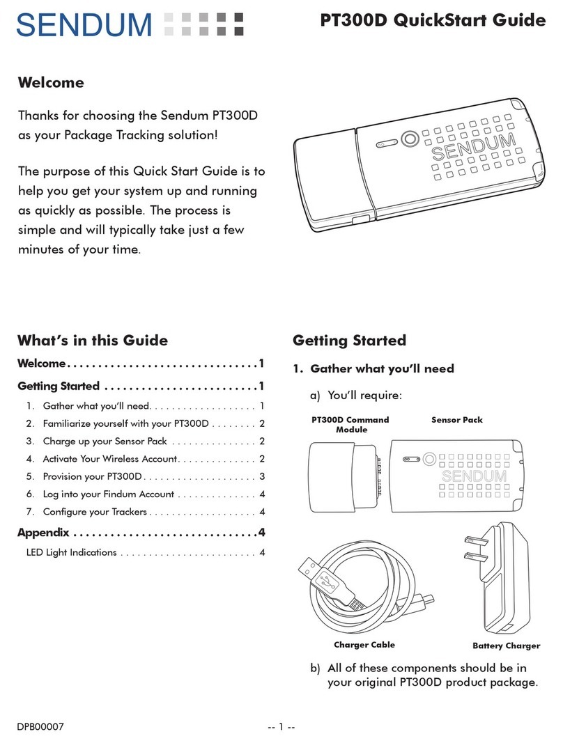
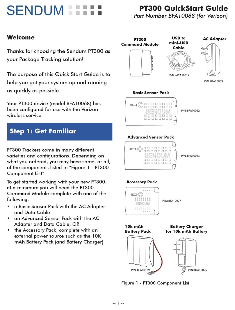
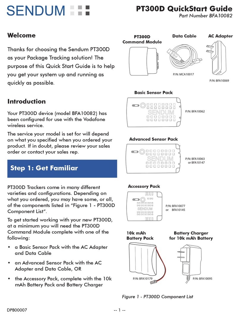
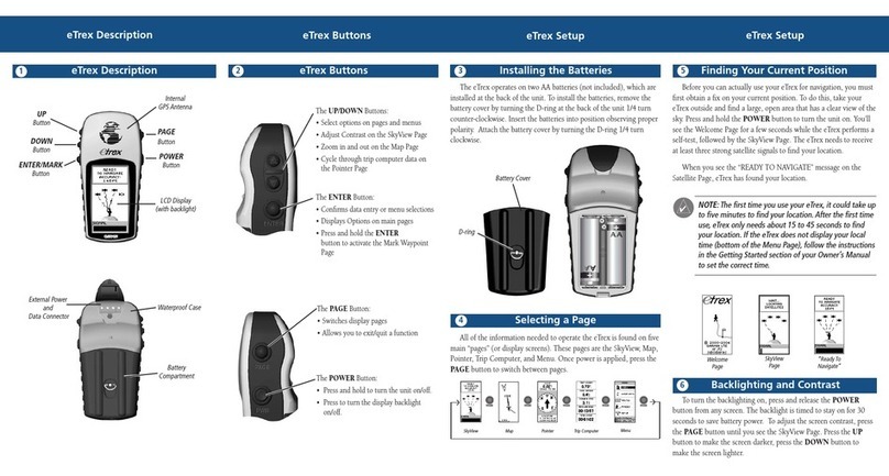
Sendum GT300 User manual

GT300 Equipment Management System
Quick Installation Guide
This document provides abbreviated installation procedures for the Sendum GT300 equipment management system.
GT300 System
The following illustration shows the Sendum GT300 system components.
BFA100XX GT300 Equipment Terminal!MCA10015 GT300 Installation Cable
General Cautions and Safety Warnings
Read these first! Before installing the Sendum GT300 system, please read the following cautions and warnings. It is
highly recommended that these cautions and warnings are read and understood. Not following them may compro-
mise job safety.
In order to prevent injury or death, all machines equipped with the Sendum GT300 system are required to have the
following warning labels clearly fixed to the machine or equipment according to the instructions.
Warning!
General Cautions and Safety Warnings GlobalTRACS Lite System Quick Installation Guide
2MAY CONTAIN U.S. AND INTERNATIONAL EXPORT CONTROLLED INFORMATION 80-JA506-1 Rev. C
General Cautions and Safety Warnings
Read these first! Before installing the GlobalTRACS Lite system, please read the following cautions
and warnings. It is highly recommended that these cautions and warnings are read and understood.
Not following them may compromise job safety.
In order to prevent injury or death, all machines equipped with the GlobalTRACS Lite system are
required to have the following warning labels (kit number 65-J5779-1) clearly fixed to the machine
according to the instructions.
These warning labels in no way supersede or allow deviation from the published requirements and
regulations found in “Title 30 of the Code of Federal Regulations (CFR).” Every operation should
conduct their own hazard assessments and meet all of the requirements of “Title 30 of the Code of
Federal Regulations (CFR)” to ensure safe operation in the storage, transportation, loading, and
blasting of explosives.
Warning!
Measure Continuity! It is critical that a good ground is established AND VERIFIED when
installing the GlobalTRACS Lite system, especially on battery-powered equipment. Both the
battery return (BAT_RTN) wire and the chassis ground (C_GND) wire on the GlobalTRACS
Lite system power/signal cable should be run to the negative side of the battery (BAT -) on battery-
powered equipment. Always verify a good ground by measuring with an ohm meter from the negative
battery terminal to where the ground wire will be attached. Continuity must be at 0 ohms. Always verify
0 ohms at both connections to ensure proper grounding is established.
Refer to all published equipment manufacturer cautions and warnings.
This machine is equipped
with a GlobalTRACS
terminal. Disconnect the
battery at the terminal
before performing electrical
maintenance or welding on
this machine.
Use of the battery disconnect
switch alone will not interrupt
power to the GlobalTRACS
terminal.
Failure to disconnect the
battery may create a shock
hazard and can cause
product damage, serious
injury or death.
04AAA_145c_QIG
15-J5773-1
Danger: This machine sends
radio frequencies that can
cause an explosion in an area
such as a blast zone, even
when power is off, resulting in
serious injury or death.
Do not transport, carry, store,
or operate this machine in an
area where the use of cellular
phones or radio frequency
devices can create an
explosion.
15-J5772-1
Warning!
General Cautions and Safety Warnings GlobalTRACS Lite System Quick Installation Guide
2MAY CONTAIN U.S. AND INTERNATIONAL EXPORT CONTROLLED INFORMATION 80-JA506-1 Rev. C
General Cautions and Safety Warnings
Read these first! Before installing the GlobalTRACS Lite system, please read the following cautions
and warnings. It is highly recommended that these cautions and warnings are read and understood.
Not following them may compromise job safety.
In order to prevent injury or death, all machines equipped with the GlobalTRACS Lite system are
required to have the following warning labels (kit number 65-J5779-1) clearly fixed to the machine
according to the instructions.
These warning labels in no way supersede or allow deviation from the published requirements and
regulations found in “Title 30 of the Code of Federal Regulations (CFR).” Every operation should
conduct their own hazard assessments and meet all of the requirements of “Title 30 of the Code of
Federal Regulations (CFR)” to ensure safe operation in the storage, transportation, loading, and
blasting of explosives.
Warning!
Measure Continuity! It is critical that a good ground is established AND VERIFIED when
installing the GlobalTRACS Lite system, especially on battery-powered equipment. Both the
battery return (BAT_RTN) wire and the chassis ground (C_GND) wire on the GlobalTRACS
Lite system power/signal cable should be run to the negative side of the battery (BAT -) on battery-
powered equipment. Always verify a good ground by measuring with an ohm meter from the negative
battery terminal to where the ground wire will be attached. Continuity must be at 0 ohms. Always verify
0 ohms at both connections to ensure proper grounding is established.
Refer to all published equipment manufacturer cautions and warnings.
This machine is equipped
with a GlobalTRACS
terminal. Disconnect the
battery at the terminal
before performing electrical
maintenance or welding on
this machine.
Use of the battery disconnect
switch alone will not interrupt
power to the GlobalTRACS
terminal.
Failure to disconnect the
battery may create a shock
hazard and can cause
product damage, serious
injury or death.
04AAA_145c_QIG
15-J5773-1
Danger: This machine sends
radio frequencies that can
cause an explosion in an area
such as a blast zone, even
when power is off, resulting in
serious injury or death.
Do not transport, carry, store,
or operate this machine in an
area where the use of cellular
phones or radio frequency
devices can create an
explosion.
15-J5772-1
Sendum Wireless Corporation!GT300 Quick Installation Guide
1
This machine is equipped with a Sendum GT300 terminal. Disconnect the battery at the terminal before
performing electrical maintenance or welding on this machine.
Use of the battery disconnect switch alone will not interrupt power to the Sendum GT300 terminal.
Failure to disconnect the battery may create a shock hazard and can cause product damage, serious in-
jury or death.
Danger: This machine send radio frequencies that can cause an explosion in an area such as a blast
zone, even when power is off, resulting in serious injury or death.
Do not transport, carry, store or operate this machine in an area where the use of cellular phones or
radio frequency devices can create an explosion.

These warning labels in no way supersede or allow deviation from the published requirements and regulations found
in “Title 30 of the Code of Federal Regulations (CFR).” Every operation should conduct their own hazard assessments
and meet all of the requirements of “Title 30 of the Code of Federal Regulations (CFR)” to ensure safe operation in the
storage, transportation, loading, and blasting of explosives.
Warning!
General Cautions and Safety Warnings GlobalTRACS Lite System Quick Installation Guide
2MAY CONTAIN U.S. AND INTERNATIONAL EXPORT CONTROLLED INFORMATION 80-JA506-1 Rev. C
General Cautions and Safety Warnings
Read these first! Before installing the GlobalTRACS Lite system, please read the following cautions
and warnings. It is highly recommended that these cautions and warnings are read and understood.
Not following them may compromise job safety.
In order to prevent injury or death, all machines equipped with the GlobalTRACS Lite system are
required to have the following warning labels (kit number 65-J5779-1) clearly fixed to the machine
according to the instructions.
These warning labels in no way supersede or allow deviation from the published requirements and
regulations found in “Title 30 of the Code of Federal Regulations (CFR).” Every operation should
conduct their own hazard assessments and meet all of the requirements of “Title 30 of the Code of
Federal Regulations (CFR)” to ensure safe operation in the storage, transportation, loading, and
blasting of explosives.
Warning!
Measure Continuity! It is critical that a good ground is established AND VERIFIED when
installing the GlobalTRACS Lite system, especially on battery-powered equipment. Both the
battery return (BAT_RTN) wire and the chassis ground (C_GND) wire on the GlobalTRACS
Lite system power/signal cable should be run to the negative side of the battery (BAT -) on battery-
powered equipment. Always verify a good ground by measuring with an ohm meter from the negative
battery terminal to where the ground wire will be attached. Continuity must be at 0 ohms. Always verify
0 ohms at both connections to ensure proper grounding is established.
Refer to all published equipment manufacturer cautions and warnings.
This machine is equipped
with a GlobalTRACS
terminal. Disconnect the
battery at the terminal
before performing electrical
maintenance or welding on
this machine.
Use of the battery disconnect
switch alone will not interrupt
power to the GlobalTRACS
terminal.
Failure to disconnect the
battery may create a shock
hazard and can cause
product damage, serious
injury or death.
04AAA_145c_QIG
15-J5773-1
Danger: This machine sends
radio frequencies that can
cause an explosion in an area
such as a blast zone, even
when power is off, resulting in
serious injury or death.
Do not transport, carry, store,
or operate this machine in an
area where the use of cellular
phones or radio frequency
devices can create an
explosion.
15-J5772-1
Refer to all published equipment manufacturer cautions and warnings.
Sendum Wireless Corporation!GT300 Quick Installation Guide
2
Measure Continuity! It is critical that a good ground is established AND VERIFIED when installing the
Sendum GT300 system, especially on battery-powered equipment. The ground (GROUND) wire on the
Sendum GT300 system power/signal cable should be run to the negative side of the battery (BAT -) on
battery powered equipment. Always verify a good ground by measuring with an ohm meter from the
negative battery terminal to where the ground wire will be attached. Continuity must be at 0 ohms. Al-
ways verify 0 ohms at both connections to ensure proper grounding is established.

Sendum GT300 System Quick Installation Procedures
Survey the Equipment
The Sendum GT300 system may not be suitable for use on certain types of heavy equipment with high vibration
specifications. Sendum recommends consulting the equipment manufacturer’s specification manual to determine if
the Sendum GT300 system can operate on the equipment.
The Sendum GT300 system operational vibration specification is 2.4g RMS. The system will operate as expected at
this vibration specification or lower. The non-operational vibration specification is 5.0g RMS. The system may not
operate as expected at this vibration specification or higher. The Sendum GT300 system is robust and can endure high
vibration, but may not operate as expected under these conditions. The system will return to normal, expected, op-
eration once vibration levels return to 2.4g RMS or lower.
Survey the equipment and identify possible internal or external installation locations. The following illustrations de-
pict several recommended installation locations.
Note
Installation locations can affect GPS performance, with external installations providing optimal GPS performance.
Survey the Equipment GlobalTRACS Lite System Quick Installation Guide
4MAY CONTAIN U.S. AND INTERNATIONAL EXPORT CONTROLLED INFORMATION 80-JA506-1 Rev. C
03AAA_108A_QIG
Terminal mounted
inside the equipment.
Terminal can be mounted internall
y
or externally on the equipment.
Sendum Wireless Corporation!GT300 Quick Installation Guide
1

Mount and Install the Sendum GT300 System Terminal
Warning!
General Cautions and Safety Warnings GlobalTRACS Lite System Quick Installation Guide
2MAY CONTAIN U.S. AND INTERNATIONAL EXPORT CONTROLLED INFORMATION 80-JA506-1 Rev. C
General Cautions and Safety Warnings
Read these first! Before installing the GlobalTRACS Lite system, please read the following cautions
and warnings. It is highly recommended that these cautions and warnings are read and understood.
Not following them may compromise job safety.
In order to prevent injury or death, all machines equipped with the GlobalTRACS Lite system are
required to have the following warning labels (kit number 65-J5779-1) clearly fixed to the machine
according to the instructions.
These warning labels in no way supersede or allow deviation from the published requirements and
regulations found in “Title 30 of the Code of Federal Regulations (CFR).” Every operation should
conduct their own hazard assessments and meet all of the requirements of “Title 30 of the Code of
Federal Regulations (CFR)” to ensure safe operation in the storage, transportation, loading, and
blasting of explosives.
Warning!
Measure Continuity! It is critical that a good ground is established AND VERIFIED when
installing the GlobalTRACS Lite system, especially on battery-powered equipment. Both the
battery return (BAT_RTN) wire and the chassis ground (C_GND) wire on the GlobalTRACS
Lite system power/signal cable should be run to the negative side of the battery (BAT -) on battery-
powered equipment. Always verify a good ground by measuring with an ohm meter from the negative
battery terminal to where the ground wire will be attached. Continuity must be at 0 ohms. Always verify
0 ohms at both connections to ensure proper grounding is established.
Refer to all published equipment manufacturer cautions and warnings.
This machine is equipped
with a GlobalTRACS
terminal. Disconnect the
battery at the terminal
before performing electrical
maintenance or welding on
this machine.
Use of the battery disconnect
switch alone will not interrupt
power to the GlobalTRACS
terminal.
Failure to disconnect the
battery may create a shock
hazard and can cause
product damage, serious
injury or death.
04AAA_145c_QIG
15-J5773-1
Danger: This machine sends
radio frequencies that can
cause an explosion in an area
such as a blast zone, even
when power is off, resulting in
serious injury or death.
Do not transport, carry, store,
or operate this machine in an
area where the use of cellular
phones or radio frequency
devices can create an
explosion.
15-J5772-1
Route Cables
The recommended best practice is to route all cables before installing the components. This ensures that the cables are
long enough to reach the designated component locations. It may be necessary to trim cable lengths to fit a specific
vehicle. DO NOT trim cables until the desired length is known.
Location and Orientation
The GT300 was designed to accommodate numerous makes and models of equipment. The following are general
guidelines to follow when locating and orienting the GT300:
• Choose a location where the GT300 will not come into contact with corrosive liquids or solvents.
• Choose a location where chains, moving parts, or other tools will not likely be stowed on top of or interfere
with the GT300 or cables.
• Do not mount the GT300 near items that may fall on it or bump cable connections.
• Choose a structurally rigid mounting location. The surface must support the full weight of the GT300 under
all circumstances.
• Install the GT300 so that the cable connections are protected from accidental damage and potential tamper-
ing. Be sure to provide enough room for cable bends or the removal of cables for servicing (4" to 6" is re-
quired).
• Choose a mounting location that avoids removable panels and plates so that equipment maintenance can be
performed without disrupting the Sendum GT300 system.
Warning!
General Cautions and Safety Warnings GlobalTRACS Lite System Quick Installation Guide
2MAY CONTAIN U.S. AND INTERNATIONAL EXPORT CONTROLLED INFORMATION 80-JA506-1 Rev. C
General Cautions and Safety Warnings
Read these first! Before installing the GlobalTRACS Lite system, please read the following cautions
and warnings. It is highly recommended that these cautions and warnings are read and understood.
Not following them may compromise job safety.
In order to prevent injury or death, all machines equipped with the GlobalTRACS Lite system are
required to have the following warning labels (kit number 65-J5779-1) clearly fixed to the machine
according to the instructions.
These warning labels in no way supersede or allow deviation from the published requirements and
regulations found in “Title 30 of the Code of Federal Regulations (CFR).” Every operation should
conduct their own hazard assessments and meet all of the requirements of “Title 30 of the Code of
Federal Regulations (CFR)” to ensure safe operation in the storage, transportation, loading, and
blasting of explosives.
Warning!
Measure Continuity! It is critical that a good ground is established AND VERIFIED when
installing the GlobalTRACS Lite system, especially on battery-powered equipment. Both the
battery return (BAT_RTN) wire and the chassis ground (C_GND) wire on the GlobalTRACS
Lite system power/signal cable should be run to the negative side of the battery (BAT -) on battery-
powered equipment. Always verify a good ground by measuring with an ohm meter from the negative
battery terminal to where the ground wire will be attached. Continuity must be at 0 ohms. Always verify
0 ohms at both connections to ensure proper grounding is established.
Refer to all published equipment manufacturer cautions and warnings.
This machine is equipped
with a GlobalTRACS
terminal. Disconnect the
battery at the terminal
before performing electrical
maintenance or welding on
this machine.
Use of the battery disconnect
switch alone will not interrupt
power to the GlobalTRACS
terminal.
Failure to disconnect the
battery may create a shock
hazard and can cause
product damage, serious
injury or death.
04AAA_145c_QIG
15-J5773-1
Danger: This machine sends
radio frequencies that can
cause an explosion in an area
such as a blast zone, even
when power is off, resulting in
serious injury or death.
Do not transport, carry, store,
or operate this machine in an
area where the use of cellular
phones or radio frequency
devices can create an
explosion.
15-J5772-1
Standard Terminal Mounting Method and Installation
1. After locating the designated installation area, follow these steps to mount the GT300:
2. Before marking and drilling, consider which direction the cable connectors will be facing when the GT300 is
finally mounted and if they will be in the best position for installation. Adjust, if necessary, to ensure cable
connectors are in the best position.
3. Using a GT300 as a template, mark one, or all, of the mounting holes.
Sendum Wireless Corporation!GT300 Quick Installation Guide
2
Before installing the components, ensure that all vehicle power is removed. Refer to General Cautions
and Safety Warnings on page 1 and page 2 before installing any component.
DO NOT install or attach any component or cable to any removable parts, such as panels or plates.

4. Use a center punch to create an indentation for the drill bit.
5. Drill the hole using a 3/16" bit.
6. Clean (debur) the edges of the new hole (especially the back side if possible) with a deburing countersink.
7. Mount the GT300 with one of the mounting bolts.
8. Hand tighten the first mounting bolt and torque to 15 to 20 inch pounds. Note
Take care not to over tighten the mounting bolts. Over tightening the mounting bolts can cause the plastic
terminal housing to crack. Do not use air tools to tighten the mounting bolts.
9. Mark the area where the remaining hole will be drilled. Swivel the terminal out of the drill area and drill the
remaining hole.
10. Finish attaching all the hardware. Hand tighten and torque to 15 to 20 inch pounds.
Adhesive Terminal Mounting Method and Installation
Important!
The adhesive tape represents a permanent terminal mounting solution. Once the adhesive tape is adhered to attach
the terminal, it is extremely difficult to remove the terminal from the equipment. Attempting to remove the terminal
can damage the component.
Warning!
General Cautions and Safety Warnings GlobalTRACS Lite System Quick Installation Guide
2MAY CONTAIN U.S. AND INTERNATIONAL EXPORT CONTROLLED INFORMATION 80-JA506-1 Rev. C
General Cautions and Safety Warnings
Read these first! Before installing the GlobalTRACS Lite system, please read the following cautions
and warnings. It is highly recommended that these cautions and warnings are read and understood.
Not following them may compromise job safety.
In order to prevent injury or death, all machines equipped with the GlobalTRACS Lite system are
required to have the following warning labels (kit number 65-J5779-1) clearly fixed to the machine
according to the instructions.
These warning labels in no way supersede or allow deviation from the published requirements and
regulations found in “Title 30 of the Code of Federal Regulations (CFR).” Every operation should
conduct their own hazard assessments and meet all of the requirements of “Title 30 of the Code of
Federal Regulations (CFR)” to ensure safe operation in the storage, transportation, loading, and
blasting of explosives.
Warning!
Measure Continuity! It is critical that a good ground is established AND VERIFIED when
installing the GlobalTRACS Lite system, especially on battery-powered equipment. Both the
battery return (BAT_RTN) wire and the chassis ground (C_GND) wire on the GlobalTRACS
Lite system power/signal cable should be run to the negative side of the battery (BAT -) on battery-
powered equipment. Always verify a good ground by measuring with an ohm meter from the negative
battery terminal to where the ground wire will be attached. Continuity must be at 0 ohms. Always verify
0 ohms at both connections to ensure proper grounding is established.
Refer to all published equipment manufacturer cautions and warnings.
This machine is equipped
with a GlobalTRACS
terminal. Disconnect the
battery at the terminal
before performing electrical
maintenance or welding on
this machine.
Use of the battery disconnect
switch alone will not interrupt
power to the GlobalTRACS
terminal.
Failure to disconnect the
battery may create a shock
hazard and can cause
product damage, serious
injury or death.
04AAA_145c_QIG
15-J5773-1
Danger: This machine sends
radio frequencies that can
cause an explosion in an area
such as a blast zone, even
when power is off, resulting in
serious injury or death.
Do not transport, carry, store,
or operate this machine in an
area where the use of cellular
phones or radio frequency
devices can create an
explosion.
15-J5772-1
1. Ensure the designated mounting surface is flat for best possible terminal installation.
2. Clean the designated mounting surface using the alcohol wipes to ensure it is free of any
contaminant, such as, oil, dirt, solvents, wax, etc.
3. Locate the double-sided adhesive pad.
Sendum Wireless Corporation!GT300 Quick Installation Guide
3
When using the double-sided adhesive pad, an initial tape application to surface temperatures below
32°F (0°C) is not recommended, due to the adhesive becoming too firm to properly adhere. To obtain a
good performance with the adhesive tapes, it is important to
ensure the mounting surfaces are clean and dry. When the adhesive tape is properly applied at a sug-
gested temperature, low temperature adhesion is satisfactory.
Suggested Adhesive Application Temperature Ranges
•The ideal tape application temperature range is between 70°F to 100°F (21°C o 38°C).
•The minimum suggested application temperature is between 32°F to 60°F (0°C to 16°C).
•Application is not recommended below 32°F (0°C).

4. Turn the terminal over.
5. Remove one side of the plastic protection film from the double-sided adhesive pad and carefully line the
pad up with the underside of the terminal.
6. Position the adhesive side of the pad onto the terminal and apply even pressure until it is fully adhered to
the terminal.
7. Remove the remaining plastic protection film, orient the terminal into position on the equipment, and attach
it.
8. Press firmly until the terminal is securely attached.
Warning!
General Cautions and Safety Warnings GlobalTRACS Lite System Quick Installation Guide
2MAY CONTAIN U.S. AND INTERNATIONAL EXPORT CONTROLLED INFORMATION 80-JA506-1 Rev. C
General Cautions and Safety Warnings
Read these first! Before installing the GlobalTRACS Lite system, please read the following cautions
and warnings. It is highly recommended that these cautions and warnings are read and understood.
Not following them may compromise job safety.
In order to prevent injury or death, all machines equipped with the GlobalTRACS Lite system are
required to have the following warning labels (kit number 65-J5779-1) clearly fixed to the machine
according to the instructions.
These warning labels in no way supersede or allow deviation from the published requirements and
regulations found in “Title 30 of the Code of Federal Regulations (CFR).” Every operation should
conduct their own hazard assessments and meet all of the requirements of “Title 30 of the Code of
Federal Regulations (CFR)” to ensure safe operation in the storage, transportation, loading, and
blasting of explosives.
Warning!
Measure Continuity! It is critical that a good ground is established AND VERIFIED when
installing the GlobalTRACS Lite system, especially on battery-powered equipment. Both the
battery return (BAT_RTN) wire and the chassis ground (C_GND) wire on the GlobalTRACS
Lite system power/signal cable should be run to the negative side of the battery (BAT -) on battery-
powered equipment. Always verify a good ground by measuring with an ohm meter from the negative
battery terminal to where the ground wire will be attached. Continuity must be at 0 ohms. Always verify
0 ohms at both connections to ensure proper grounding is established.
Refer to all published equipment manufacturer cautions and warnings.
This machine is equipped
with a GlobalTRACS
terminal. Disconnect the
battery at the terminal
before performing electrical
maintenance or welding on
this machine.
Use of the battery disconnect
switch alone will not interrupt
power to the GlobalTRACS
terminal.
Failure to disconnect the
battery may create a shock
hazard and can cause
product damage, serious
injury or death.
04AAA_145c_QIG
15-J5773-1
Danger: This machine sends
radio frequencies that can
cause an explosion in an area
such as a blast zone, even
when power is off, resulting in
serious injury or death.
Do not transport, carry, store,
or operate this machine in an
area where the use of cellular
phones or radio frequency
devices can create an
explosion.
15-J5772-1
Warning!
General Cautions and Safety Warnings GlobalTRACS Lite System Quick Installation Guide
2MAY CONTAIN U.S. AND INTERNATIONAL EXPORT CONTROLLED INFORMATION 80-JA506-1 Rev. C
General Cautions and Safety Warnings
Read these first! Before installing the GlobalTRACS Lite system, please read the following cautions
and warnings. It is highly recommended that these cautions and warnings are read and understood.
Not following them may compromise job safety.
In order to prevent injury or death, all machines equipped with the GlobalTRACS Lite system are
required to have the following warning labels (kit number 65-J5779-1) clearly fixed to the machine
according to the instructions.
These warning labels in no way supersede or allow deviation from the published requirements and
regulations found in “Title 30 of the Code of Federal Regulations (CFR).” Every operation should
conduct their own hazard assessments and meet all of the requirements of “Title 30 of the Code of
Federal Regulations (CFR)” to ensure safe operation in the storage, transportation, loading, and
blasting of explosives.
Warning!
Measure Continuity! It is critical that a good ground is established AND VERIFIED when
installing the GlobalTRACS Lite system, especially on battery-powered equipment. Both the
battery return (BAT_RTN) wire and the chassis ground (C_GND) wire on the GlobalTRACS
Lite system power/signal cable should be run to the negative side of the battery (BAT -) on battery-
powered equipment. Always verify a good ground by measuring with an ohm meter from the negative
battery terminal to where the ground wire will be attached. Continuity must be at 0 ohms. Always verify
0 ohms at both connections to ensure proper grounding is established.
Refer to all published equipment manufacturer cautions and warnings.
This machine is equipped
with a GlobalTRACS
terminal. Disconnect the
battery at the terminal
before performing electrical
maintenance or welding on
this machine.
Use of the battery disconnect
switch alone will not interrupt
power to the GlobalTRACS
terminal.
Failure to disconnect the
battery may create a shock
hazard and can cause
product damage, serious
injury or death.
04AAA_145c_QIG
15-J5773-1
Danger: This machine sends
radio frequencies that can
cause an explosion in an area
such as a blast zone, even
when power is off, resulting in
serious injury or death.
Do not transport, carry, store,
or operate this machine in an
area where the use of cellular
phones or radio frequency
devices can create an
explosion.
15-J5772-1
1. Route the power/signal cable from the GT300 to the designated vehicle power source.
2. Attach one 3-amp fuse to the power wire.:
• black BATTERY - one 3-amp fuse.
• white GROUND - no fuse required.
• violet INPUT - no fuse required.
• orange RUN_TERM - no fuse required.
Sendum Wireless Corporation!GT300 Quick Installation Guide
4
Practice extreme caution when wiring certain types of equipment, such as generators. Lethal voltages
can be present on certain types of equipment and can cause injury or death.
When working on battery-powered equipment, do not bring any type of flame, spark, etc., near the
battery. Gas formed while the battery is charging is highly explosive.This gas remains in the cells long
after charging has stopped. Do not lay metallic or conductive objects on the battery. Arcing will result.
Battery Capacitance. Due to capacitance voltages present in battery-powered equipment, whenever
performing maintenance which may prevent contact with bus bars and associated power cables, you
should discharge the capacitors following the recommended procedures written in the equipment
maintenance manual.

Power/Signal Cable Wire Connections For Diesel Powered Equipment
The equipment battery supplies the power to the GT300 There are four required wire connections that you must
make from the power/signal cable:
• BATTERY (black) to +12 VDC or +24 VDC battery
•GROUND (white) to battery negative (BAT -) or ground
•INPUT (violet) to sensor (contact Sendum).
•RUN_TERM (orange) to run terminal on the alternator (minimum 7.5 VDC present when engine is running)
Diesel Powered Equipment Wire Connection Table
BATTERY
(Constant 12 VDC or 24
VDC)
GROUND
(BAT –/Ground or
Ground)
RUN_TERM
(Measures engine hours)
INPUT
•Alternator (constant 12
VDC or 24 VDC)
•High side of vehicle
main wiring bus.
•Battery side of the fuse
box. (Not the load side.)
•Battery side of the igni-
tion switch.
•Battery side of the cut-
out switch. (Must obtain
permission from cus-
tomer to connect here.)
•Chassis side of the cut-
out switch. (Note that
the GT300 will not op-
erate if the disconnect
switch is open.)
•Good ground (BAT –).
•Run terminal on the
alternator.
• Hour meter.
•Oil pressure switch.
•Ignition or ON/OFF
(Run) switch.
•Contact Sendum.
Caution
When establishing a good
chassis ground, avoid ar-
eas that may be poten-
tially isolated from ground
by a hinge or some welds.
Note:
Selecting the appropriate
RUN_TERM connection
point will determine what
equipment function is
being measured, e.g., ac-
tual ignition ON time or
work time.
Sendum Wireless Corporation!GT300 Quick Installation Guide
5

Power/Signal Cable Wire Connections For Battery Powered Equipment
The equipment battery supplies the power to the GT300. There are four required wire connections that you must
make from the power/signal cable:
• BATTERY (black) to +12 VDC or +24 VDC battery
• GROUND (white) to battery negative (BAT -)
• INPUT (violet) is for sensor input (contact Sendum).
• RUN_TERM (orange) to either switched ignition or the hours meter (minimum 7.5 VDC present when en-
gine is running)
Warning!
General Cautions and Safety Warnings GlobalTRACS Lite System Quick Installation Guide
2MAY CONTAIN U.S. AND INTERNATIONAL EXPORT CONTROLLED INFORMATION 80-JA506-1 Rev. C
General Cautions and Safety Warnings
Read these first! Before installing the GlobalTRACS Lite system, please read the following cautions
and warnings. It is highly recommended that these cautions and warnings are read and understood.
Not following them may compromise job safety.
In order to prevent injury or death, all machines equipped with the GlobalTRACS Lite system are
required to have the following warning labels (kit number 65-J5779-1) clearly fixed to the machine
according to the instructions.
These warning labels in no way supersede or allow deviation from the published requirements and
regulations found in “Title 30 of the Code of Federal Regulations (CFR).” Every operation should
conduct their own hazard assessments and meet all of the requirements of “Title 30 of the Code of
Federal Regulations (CFR)” to ensure safe operation in the storage, transportation, loading, and
blasting of explosives.
Warning!
Measure Continuity! It is critical that a good ground is established AND VERIFIED when
installing the GlobalTRACS Lite system, especially on battery-powered equipment. Both the
battery return (BAT_RTN) wire and the chassis ground (C_GND) wire on the GlobalTRACS
Lite system power/signal cable should be run to the negative side of the battery (BAT -) on battery-
powered equipment. Always verify a good ground by measuring with an ohm meter from the negative
battery terminal to where the ground wire will be attached. Continuity must be at 0 ohms. Always verify
0 ohms at both connections to ensure proper grounding is established.
Refer to all published equipment manufacturer cautions and warnings.
This machine is equipped
with a GlobalTRACS
terminal. Disconnect the
battery at the terminal
before performing electrical
maintenance or welding on
this machine.
Use of the battery disconnect
switch alone will not interrupt
power to the GlobalTRACS
terminal.
Failure to disconnect the
battery may create a shock
hazard and can cause
product damage, serious
injury or death.
04AAA_145c_QIG
15-J5773-1
Danger: This machine sends
radio frequencies that can
cause an explosion in an area
such as a blast zone, even
when power is off, resulting in
serious injury or death.
Do not transport, carry, store,
or operate this machine in an
area where the use of cellular
phones or radio frequency
devices can create an
explosion.
15-J5772-1
Battery-powered Equipment Wire Connection Table
BAT +
(Constant 12 VDC or 24
VDC)
GROUND
(BAT –/Ground)
RUN_TERM
(Measures engine hours)
INPUT
•Alternator (constant 12
VDC or 24 VDC)
•High side of vehicle
main wiring bus.
•Battery side of the fuse
box. (Not the load side.)
•Battery side of the igni-
tion switch.
•Negative side of the
battery (BAT -)
• Hour meter.
•Ignition or ON/OFF
(Run) switch.
•Contact Sendum
Caution
When establishing a good
chassis ground, avoid ar-
eas that may be poten-
tially isolated from ground
by a hinge or some welds.
Note:
Selecting the appropriate
RUN_TERM connection
point will determine what
equipment function is
being measured, e.g., ac-
tual ignition ON time or
work time.
Sendum Wireless Corporation!GT300 Quick Installation Guide
6
Measure Continuity! It is critical that a good ground is established AND VERIFIED when installing
the Sendum GT300 system, especially on battery-powered equipment. The ground (GROUND) wire on
the Sendum GT300 system power/signal cable should be run to the negative side of the battery (BAT -)
on battery- powered equipment. Always verify a good ground by measuring with an ohm meter from
the negative battery terminal to where the ground wire will be attached. Continuity must be at 0 ohms.
Always verify 0 ohms at both connections to ensure proper grounding is established.

Sendum Wireless Corporation
4500 Beedie Street
Buranby, BC V5J 5L2 Canada
© 2008-2012 Sendum Wireless Corporation. All rights reserved.
All trademarks are the property of their respective owners. Specifications are subject to change without notice. Sen-
dum endeavors to ensure that the information in this document is correct and fairly stated, but Sendum is not liable
for any errors or omissions. Published information may not be up to date, and it is important to confirm current
status with Sendum.
This technical data may be subject to U.S. and international export, re-export or transfer (export) laws. Diversion con-
trary to U.S. and international law is strictly prohibited.
xxxxxx Rev. B August 2012
MAY CONTAIN U.S. AND INTERNATIONAL EXPORT CONTROLLED INFORMATION
Sendum Wireless Corporation!GT300 Quick Installation Guide
7
Other Sendum GPS manuals

