Seneca MyBoat User manual

INSTALLATION MANUAL
MyBoat
Real time remote control and alarm management
device for boats
SENECA s.r.l.
Via Austria, 26 – 35127 – PADOVA – ITALY
Tel. +39.049.8705355 - 8705359 - Fax +39.049.8706287
For manuals in other languages and the conguration software, visit www.seneca.it/myboat
EN
MI00498-2-EN 1/8
MODULE LAYOUT
PRELIMINARY WARNINGS
The word WARNING preceded by the symbol indicates conditions or actions that put the user's safety at
risk. The word ATTENTION preceded by the symbol indicates conditions or actions that might damage the
instrument or the connected equipment.
The warranty shall become null and void in the event of improper use or tampering with the module or devices
supplied by the manufacturer as necessary for its correct operation, and if the instructions contained in this
manual are not followed.
WARNING: The full content of this manual must be read before any operation. The module must only be used by
qualied electricians. Specic documentation is available at www.seneca.it/myboat
Important: Obstructing ventilation slots with any object is prohibited.
Installing the module next to devices that generate heat is prohibited.
Electrical and electronic waste disposal (applicable in the European Union and other countries with recycling).
The symbol on the product or its packaging shows the product must be surrendered to a collection centre
authorized to recycle electrical and electronic waste.
The module must be repaired and damaged parts replaced by the Manufacturer. The product is sensitive to
electrostatic discharges. Take appropriate measures during any operation.
LED STATUS LED meaning
GSM
(Yellow)
Slow ashing GSM network registration successful, but internet
connection not active
Fast ashing
Network search / no signal / SIM card with incorrect PIN
Medium ashing
Network access successful; APN correct; registration to the
GPS network active
PWR
(Green)
ON Device ON
OFF Device OFF
SIGNALS VIA LED ON FRONT PANEL
2/8
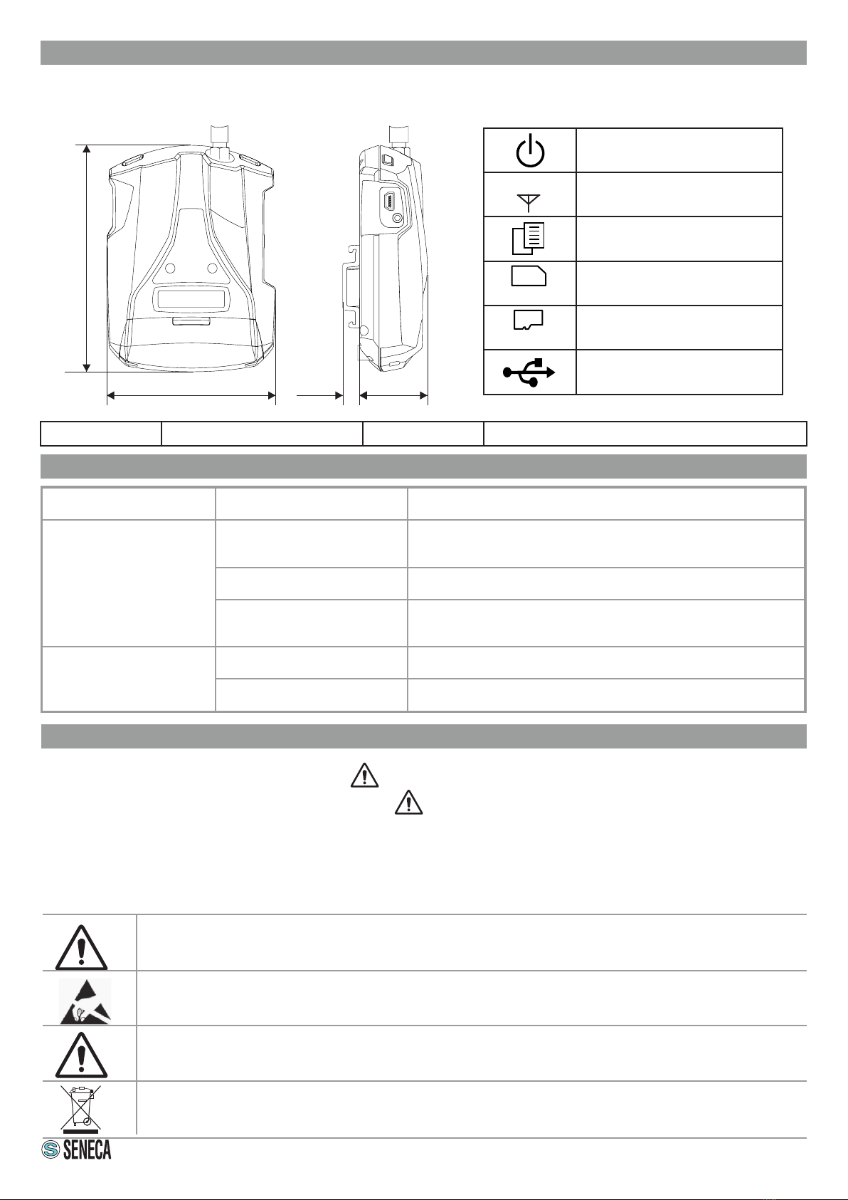
80 mm
108 mm
32 mm
8 mm
CASE DIMENSIONS SYMBOLS ON THE ENCLOSURE
ON / OFF power button
GPS antenna
Menu access button
Slot for mini SIM
Slot for micro SD card
Micro USB connector
Weight 150 g Case Polycarbonate / ABS material
GPS
SIM
SD
POWER SUPPLY
Voltage
Internal battery absorption
6 – 15 Vdc, 500 mA Max.
3.5 W Max.
Lithium Ions 3.7 V - 1100 mAh, rechargeable non-replaceable.
DIGITAL INPUTS
Type
Maximum frequency
Threshold OFF
Threshold ON
4 inputs
Reed, contact, PNP, Pulsecap
30 Hz
0 - 3 Vdc, I < 1mA
6 - 24 Vdc, I > 3mA
ANALOGUE INPUTS
Type
Precision
2 inputs
Voltage 0 - 30 Vdc / Current 0 - 20 mA
0.1% of full scale
VOLTAGE OUTPUT: +12 Vdc 50 mA (maximum current)
TEMPERATURE SENSOR NTC thermistor internal (as standard), external (option)
USB PORT
1 reserved micro USB port
DISPLAY
128 x 32 LCD Dots with visible area of 39 mm x 8.6 mm
CONNECTIONS
Spring clamps, 3.5 mm pitch, connector for Micro USB and
SMA connector for GSM Antenna
CPU
ARM 100 Mhz 32 bit
INTERNAL MEMORY
FLASH 2 MByte (log)
Micro SD slot
Push-Push for SD card and SD HC card / max 32GB
SIM slot
Push-Push for mini SIM (15 x 25 mm)
GSM
Quad band (850 / 900 / 1800 / 1900 MHz)
MMCX CONNECTOR
External GPS antenna connector (optional)
ENVIRONMENTAL CONDITIONS
Temperature
Humidity
Storage temperature
Protection rating
Seneca recommends use at 0 to 45 ° C for correct operation.
With the power supply present: -20 .. +55°C
With use of the battery (when discharged): -20 .. +45°C
Charging is possible in the range: 0 .. +45°C
30%– 90% non condensing.
from -20°C to +20°C < 1 year; from -20°C to +45°C < 3 months; from -20°C to +60°C < 1 month
IP20
RECEIVER 22 channels
SENSITIVITY -165 dBm
FIX TIME 32 s usually
ACCURACY Up to 2.5 m
TECHNOLOGY LoRa ®
POWER SUPPLY
CR2 3V battery (replaceable)
FREQUENCY BAND
863 ÷ 870 MHz
SENSITIVITY
up to -146 dBm
RF POWER
+14 dBm
TECHNICAL SPECIFICATIONS
3/8
GPS CARD SPECIFICATIONS (OPTION)
RECEIVER AND SENSOR SPECIFICATIONS
RELAY EXPANSION CARD SPECIFICATIONS (OPTIONAL)
TECHNOLOGY 2 outlets Relay 3 A max - 250 V SPST (with shared terminal)
STANDARDS ETSI EN301 489-7; EN301 511; EN301 489-1; IEC / EN 60950; IEC 60086
REFERENCE STANDARDS
4/8
INITIAL POWERING ON OF THE DEVICE
MyBoat is supplied in “shipping mode”. This mode prevents any unnecessary discharge of the battery during
transport as well as any accidental switch-ons.
When switched on for the rst time, power the device with the power cord supplied; this allows "shipping
mode" to be exited.
N.B.: During "shipping mode" the power button is disabled.
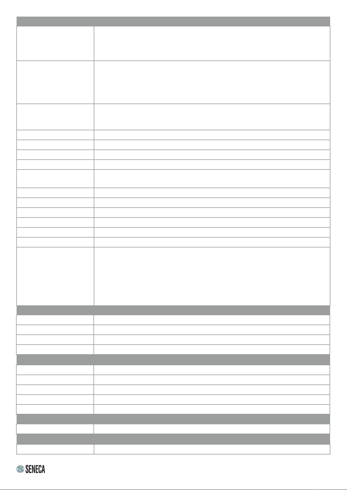
ON/OFF BUTTON AND SCROLL DISPLAY BUTTON
MyBoat is equipped with a PWR button located on the top left side (front panel
view). Pressing this button turns the module on and off. To switch it off, hold the
PWR key down for a few seconds.
MyBoat is also equipped with a SCR button, located on the top right side (front
panel view). Pressing this key displays the parameters.
MICRO USB PORT AND POWER SUPPLY
The device has a micro USB connector on the left side of its enclosure, which can
be used for conguration, rmware updates and to recharge the internal battery.
To recharge the internal battery, use:
- the 12 V power supply (supplied) by connecting the cables to the + and -
terminals (GND).
- a PC via the micro USB port with a standard cable.
Power supply through the USB jack is not suitable for xed installations, or
congurations where relays and/or digital inputs are used.
PWR SCR
ANTENNA
ANTENNA
micro
USB
AUTO POWER-OFF
If the display shows”LOW BAT”, it means that the internal battery is low, after 60 seconds the device switches off
automatically.
To restore the battery charge to an appropriate value, recharge the device using one of the recommended modes.
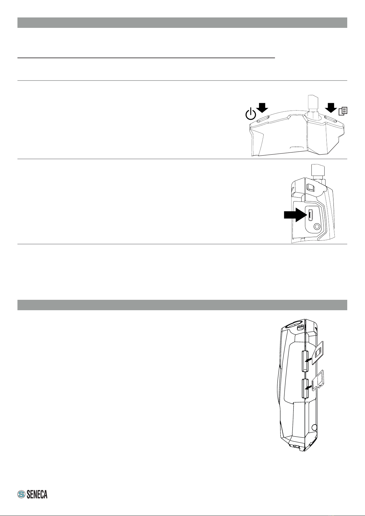
INSERTING THE SIM CARD AND SD CARD
INSERTING THE SIM CARD
MyBoat has a slot for mini SIM located in the right side of the enclosure.
To insert the card in its corresponding slot, make sure the metal contacts are
facing right (as seen in the gure).
INSERTING THE SD CARD
MyBoat is equipped with an SD card input that can be used to update the device's
rmware and the information and connection parameters with the world's best
known telephony operators.
Note: DO NOT REMOVE THE CONTENT OF THE SD CARD PROVIDED. THIS
MAY RESULT IN FAILED DATA CONNECTION WITH THE MyBoat SERVICE.
The input for micro SD card is located on the right side of the enclosure.
To insert the SD card in its corresponding slot, make sure the metal contacts are
facing right (as seen in the gure).
SIM
card
SD
card

5/8
ASSEMBLY REGULATIONS
For optimal reception of the GPS signal given by the satellites, MyBoat should be positioned in an area not
covered by metal structures. If this is not possible or if the satellite reception is no good, an optional external
antenna with 3m cable (code A-GPS) is available. Follow the procedure supplied with the package for the
installation of the external antenna.
SAFETY INFORMATION
The MyBoat control unit has a terminal block inside its
enclosure.
To access the internal terminal block of the device,
unscrew the screw at the centre of the black cover
positioned at the bottom of the enclosure and lift up.
In the side gure, the cover has been removed.
IMPORTANT: With the relay card, mobile wiring of
cables connected to terminals is not permitted.
To make the cables from the terminals safe, use the
break-out passages in the back of the enclosure.
When the wiring is complete, fasten the protective cover
on the device with the screw to prevent any accidental
contact.
12
3
456 789 10 11 12 -
+
13
6/8
ELECTRICAL CONNECTIONS
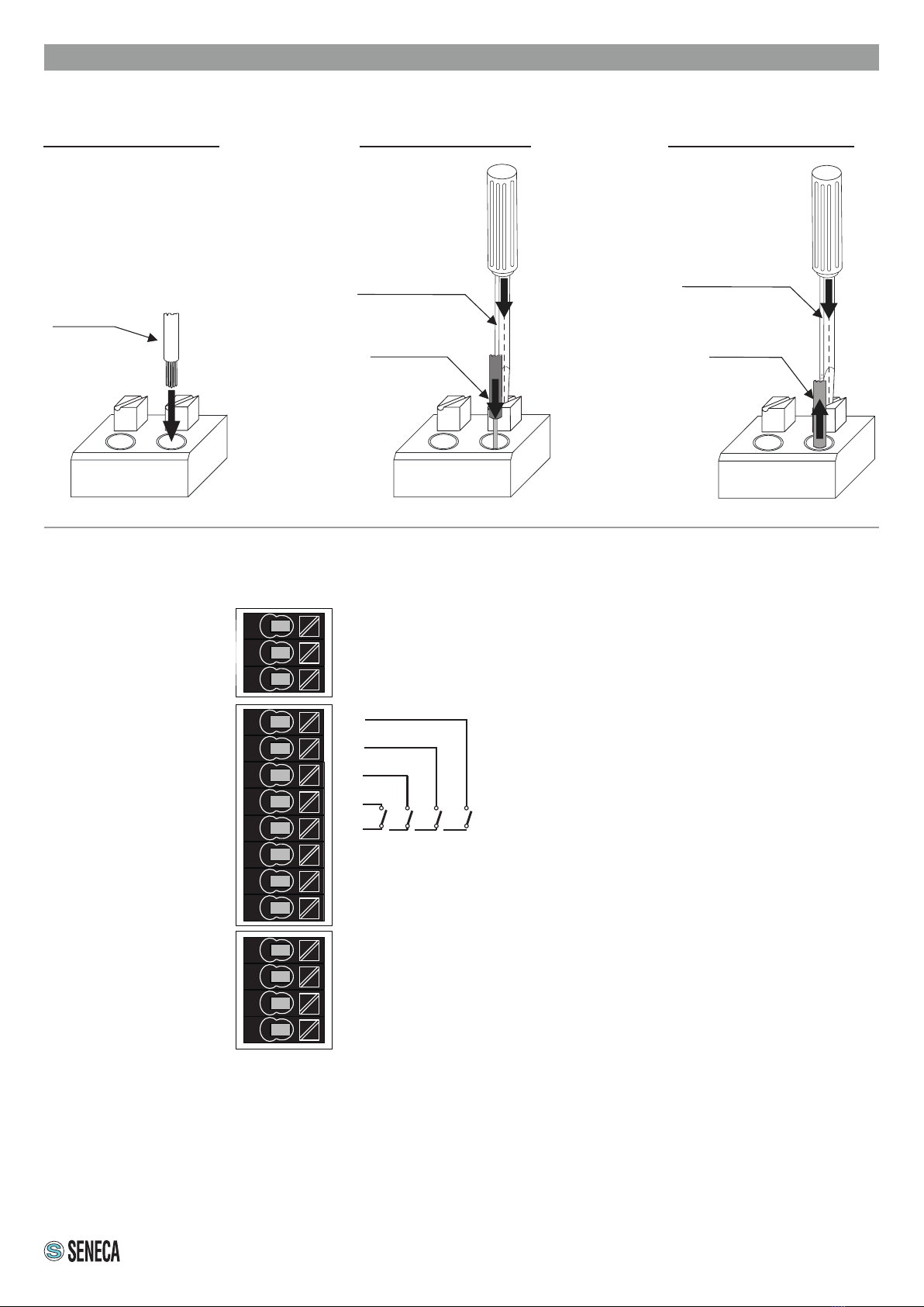
INSERTION AND EXTRACTION FROM TERMINALS WITH A PUSH-WIRE CONNECTION
Insertion of a rigid cable
Press
down Recommended aying:
8-9 mm
Insertion of a thin cable Extraction of a rigid cable
A: press with a
screwdriver
B: insert
the cable
A: press with a
screwdriver
B: extract
the cable
PUSH-WIRE TERMINAL BLOCK
1
2
3
4
5
6
7
8
9
10
11
12
13
+
-
(timed) AUX 1
Common to the two relays (*)
(Not timed) AUX 2
(normally closed) DIN 1
AUX +12 Vdc
GND
(service battery sensor) AIN 1
0 V = 0%; 10 V = 100% AIN 2
GND
(Sensor input) NTC
+ Power
- Power
(normally closed) DIN 2
(normally closed) DIN 3
(normally closed) DIN 4

7/8
BATTERY REPLACEMENT
Use a Phillips screwdriver and remove the screws (reference 1 and 2).
Open the top cover, remove the battery and insert a new CR2 battery, with the correct polarity (see following
image).
Replace the cover and tighten the screws firmly all the way.
Do not overtighten the screws to avoid breaking the cover.
Pairing begins automatically and the Rx led starts flashing.
Note:
- Do not lose the cover and screws.
- The battery supplied at the time of purchase may have a shorter life span, as it is installed at the factory to check
performance
REFERENCE IMAGE:
1 2
CAUTION
Do not use sharp objects to remove the battery.
Old batteries cannot be disposed of in household waste, it is mandatory to return them to the appropriate collection place,
prepared by the municipality or point of sale.
Spent batteries contain heavy metals or material harmful to the environment and health. Since they also contain important
elements such as iron, zinc, manganese and nickel, they can be recycled.
We recommend using batteries of the same type inside a device, the use of batteries of different types could cause liquid
leakage or battery breakage, or damage the device in use.
Always replace the battery or batteries of the device used with batteries of the size and type specied by the manufacturer.
Do not apply pressure or shocks to the battery, this might damage it and cause liquid leakage or breakage.
Do not expose the instrumentation to extreme, high or low temperatures or pressures, this might cause an explosion or
leakage of ammable liquids or gases.
In the presence of odours, swellings, cracks or loose or missing caps, the batteries must be considered "damaged".
Damaged batteries can release dangerous chemicals and require a special disposal process. Contact the manufacturer's
customer service for advice on treating damaged batteries.
ACCESSORIES
OPTIONAL ACCESSORIES
A-GPS External GPS antenna with 3 m cable
A-GSM/QUAD-N External GSM / QUAND-N antenna with 5 m cable
SPARE ACCESSORIES
CPS-TIP-MP Spare cigarette lighter power supply
MYBOAT-S1 Replacement sensor for access control
MYBOAT-S2 Replacement sensor for bilge monitoring
MYBOAT-S3 Replacement sensor for access control
MYBOAT-S4 Replacement sensor for battery monitoring
MYBOAT-S5 Replacement sensor for battery monitoring
MYBOAT-S6 Replacement sensor for bilge monitoring
MYBOAT-S7 Replacement sensor for access control
MYBOAT-S8 Replacement sensor for access control
CONTACT INFORMATION
This document is the property of SENECA srl. Copies and reproduction are prohibited unless authorised.
The content of this document corresponds to the described products and technologies.
Stated data may be modied or supplemented for technical and/or sales purposes.
8/8
Other manuals for MyBoat
2
Table of contents


