SenerTec Dachs MSR1 Guide
Art. Nr.: 09/4798.214.004 © Änderungen und Irrtum vorbehalten
1
Dachs - MSR1/MSR2
DE
GB
IT
ES
Anleitung zur instAllAtion und einstellung der
ThermosTaTpumpe
instructions for the instAllAtion And Adjustment
o f the ThermosTaTic pump
istruzione per l'instAllAzione el A regolAzione dellA
pompa TermosTaTica
instrucciones pArA l A instAlAción ye l Ajuste d e l A
BomBa TermosTáTica
2-7
8-13
14-19
20-28
Lesen Sie diese Anleitung vor Beginn der Arbeiten am Dachs sorgfältig durch.
Alle Gewährleistungsansprüche entfallen, wenn Sie diese Anleitung nicht beachten.
Eintragungen in DABS nicht vergessen !
Read these instructions carefully before commencing work on the Dachs.
All warranty claims are void if you do not observe these instructions.
Do not forget entries in DABS !
Leggere attentamente queste istruzioni prima di effettuare qualsiasi operazione sul Dachs.
Qualsiasi garanzia decade qualora non ci si attenga alle prescrizioni contenute in queste istruzioni.
Non dimenticarsi l’inserimento dati nel DABS !
DE
GB
IT
ES
Lea detenidamente estas instrucciones de transporte.
No podrá hacer valer ningún derecho de garantía si no observa estas instrucciones de transporte.
¡ No olvide introducir los datos en el sistema DABS !

2
deutsch
DE
Art. Nr.: 09/4798.214.004 © Änderungen und Irrtum vorbehalten
Sicherheit
Bei der Montage, Inbetriebnahme und Wartung sind die einschlägigen Sicherheitsbestimmungen nach
DIN, DVGW, VDE, TAB und der EU zu beachten und einzuhalten.
Dieses Zeichen steht vor allen wichtigen Sicherheitshinweisen. Befolgen Sie diese, um Gefahren und
Schäden für Mensch und Sachwerte auszuschließen.
Sicherheit
Allgemeine Hinweise
EG-Konformität und nationale Vorschriften, Richtlinien und Normen
Unsere Dachs-Produkte mit CE-Zeichen sind nach den zum Zeitpunkt der Prüfung gültigen EG-Richtlinien
entwickelt und gefertigt. Der Hersteller des Produktes bestätigt dies durch eine EG-Konformitätserklärung
und durch die Kennzeichnung des Produktes mit dem CE-Zeichen.
Geräte, die der EG-Gasgeräterichtlinie unterliegen, sind durch akkreditierte Prüfstellen geprüft und zerti-
fiziert, erkennbar neben dem CE-Zeichen durch die Angabe der Prüfstellen ID-Nummer.
In den meisten Ländern gibt es für die Installation und Inbetriebnahme von Geräten im Gebäude keine
harmonisierten EU-Vorschriften und Regelungen. Bei der Installation der Dachs-Produkte müssen daher
von der verantwortlichen Installationsfirma die nationalen Vorschriften, Richtlinien und Normen des jewei-
ligen Landes berücksichtigt werden.

3
deutsch
DE
Art. Nr.: 09/4798.214.004 © Änderungen und Irrtum vorbehalten
Anwendungsbereiche
Die Thermostatpumpe wird eingesetzt bei:
Einmodulanlagen mit Pufferspeicher, wenn eine Vordruckpumpe erforderlich ist
(z.B. große Leitungslängen, Systemtrennung, Wärmemengenzähler)
Mehrmodulanlagen mit Pufferspeicher (bis 3 Dachse je Pumpenthermostat)
um den Pufferspeicher mit ca. 70-80 °C warmen Wasser zu beschicken, damit die Schichtung des Spei-
chers gewährleistet ist.
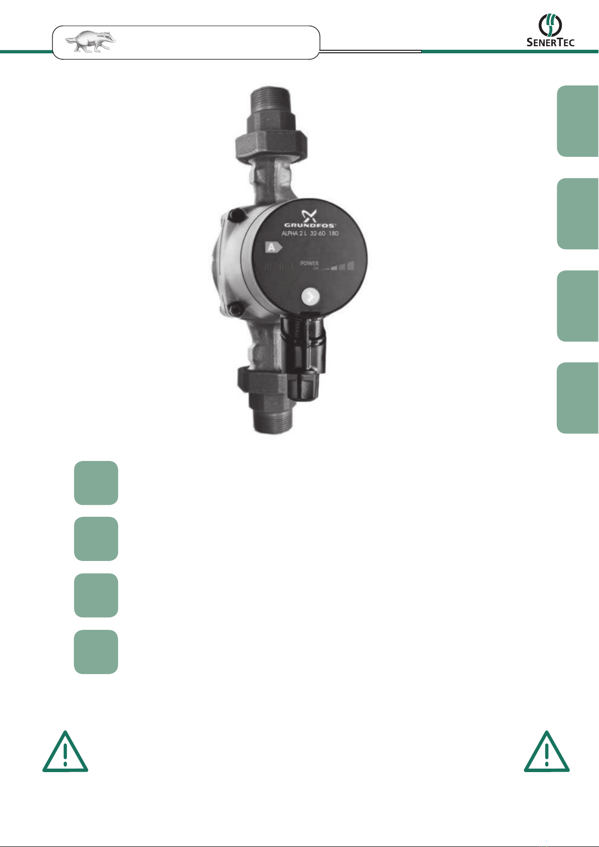
Lieferumfang
durchflussgeregelte Pumpe
Anschlussverschraubung Druckseite:
(1 1/4" AG incl. Flachdichtung)
Anschlussverschraubung Saugseite:
(1 1/4" AG, modifiziert für Thermostataufnahme incl. Flachdichtung)
Einbaulänge: 180 mm (Pumpenabmessung; ohne Anschlussverschraubung auf 1 1/4")
Förderhöhe: 1,5 m bei 3 m³/h (3 Dachse)
Thermostat (70 °C)
2 m Anschlusskabel
Kurzbeschreibung
Ein- und Mehrmodulanlagen mit Pufferspeicher, deren Anschlussleitungen zwischen Dachs und Puffer-
speicher einen Widerstand von mehr als 20 mbar aufweisen, benötigen eine Umwälzpumpe im Anschluss-
kreislauf (siehe Anlagenschema 1 und 3). Würde man eine Standardheizungspumpe ohne Temperatur- und
Durchflussregelung einsetzen, könnte keine Schichtung im Pufferspeicher erreicht werden.
Die Dachs Thermostatpumpe löst diese Aufgabe. Ein im Zulauf der Pumpe integrierter Thermostat regelt
die Vorlauftemperatur zum Pufferspeicher auf ca. 70-80 °C ein. Die elektronisch geregelte Heizungs-
pumpe passt sich über die Differenzdruckregelung an die benötigte Durchflussmenge an und spart damit
Stromkosten im Teillastbetrieb.
Mit der Thermostatpumpe wird die Vorlauftemperatur konstant geregelt und die Durchflussmenge auto-
matisch angepasst.
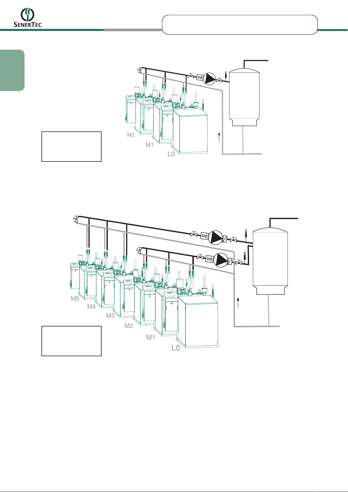
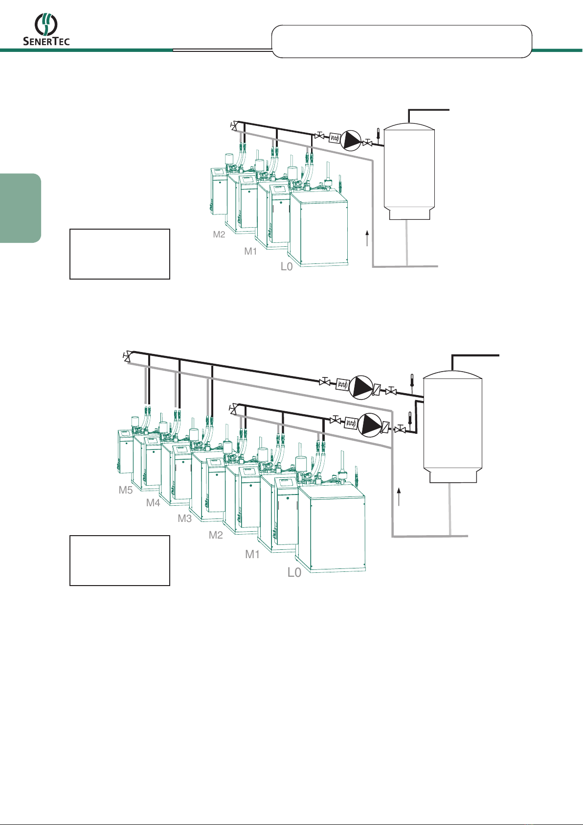
Sie ist geeignet für 1 bis 3 Dachse in einem Kreislauf. Weitere Dachse können mit einem zweiten Kreislauf
und einer zweiten Thermostatpumpe am Pufferspeicher angebunden werden (siehe Anlagenschema 4).
Puffer-
speicher
Anlagenschema 1: Einmodulanlage Anlagenschema 2: Systemtrennung
Puffer-
speicher
4
deutsch
DE
Art. Nr.: 09/4798.214.004 © Änderungen und Irrtum vorbehalten
Puffer-
speicher
L0
M1
M2
L1 /
(Leitregler)
M2 /
M3 /
1)
Puffer-
speicher
L0
M1
M2
M3
M4
M5
L1 /
(Leitregler)
M2 /
M3 /
M4 /
M5 /
M6 /
1)
1)
Anlagenschema 4: Mehrmodulanlage (mehr als 3 Dachse)
Anlagenschema 3: Mehrmodulanlage (bis 3 Dachse)
Alle hydraulischen Schaltbilder sind als Prinzipschaltbilder, nur mit den zur Thermostatpumpe betreffenden
Bauteilen, dargestellt. Sonstige Absperrungen, Ausdehnungsgefäße, etc. fehlen.
1) Die Absperrungen im Ringleitungskurzschluss sind im Regelfall geschlossen.
2) Thermostatpumpe möglichst in Dachs-Nähe platzieren, damit das Thermostat schnell anspricht.
Modulbezeichnung
für MSR2: schwarz
für MSR1: grau
Modulbezeichnung
für MSR2: schwarz
für MSR1: grau
2)
2)
2)

5
deutsch
DE
Art. Nr.: 09/4798.214.004 © Änderungen und Irrtum vorbehalten
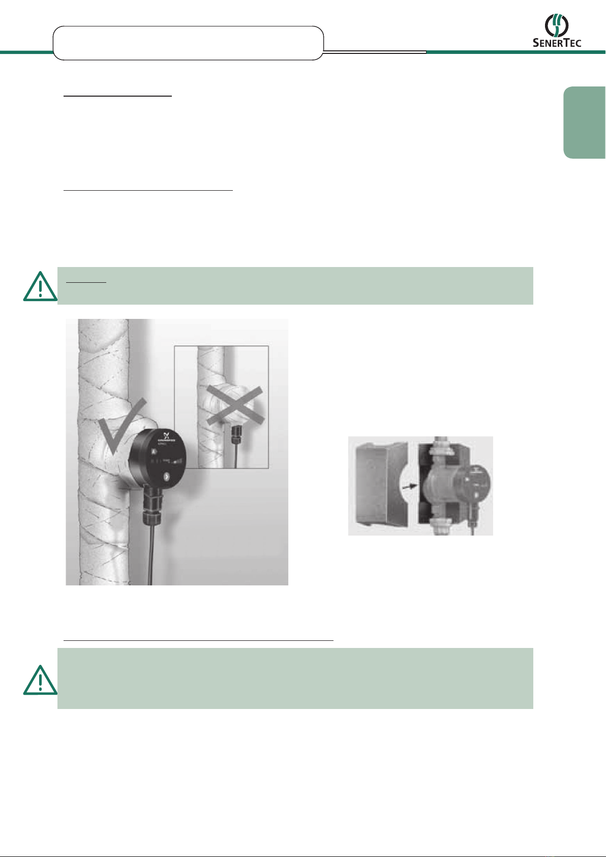
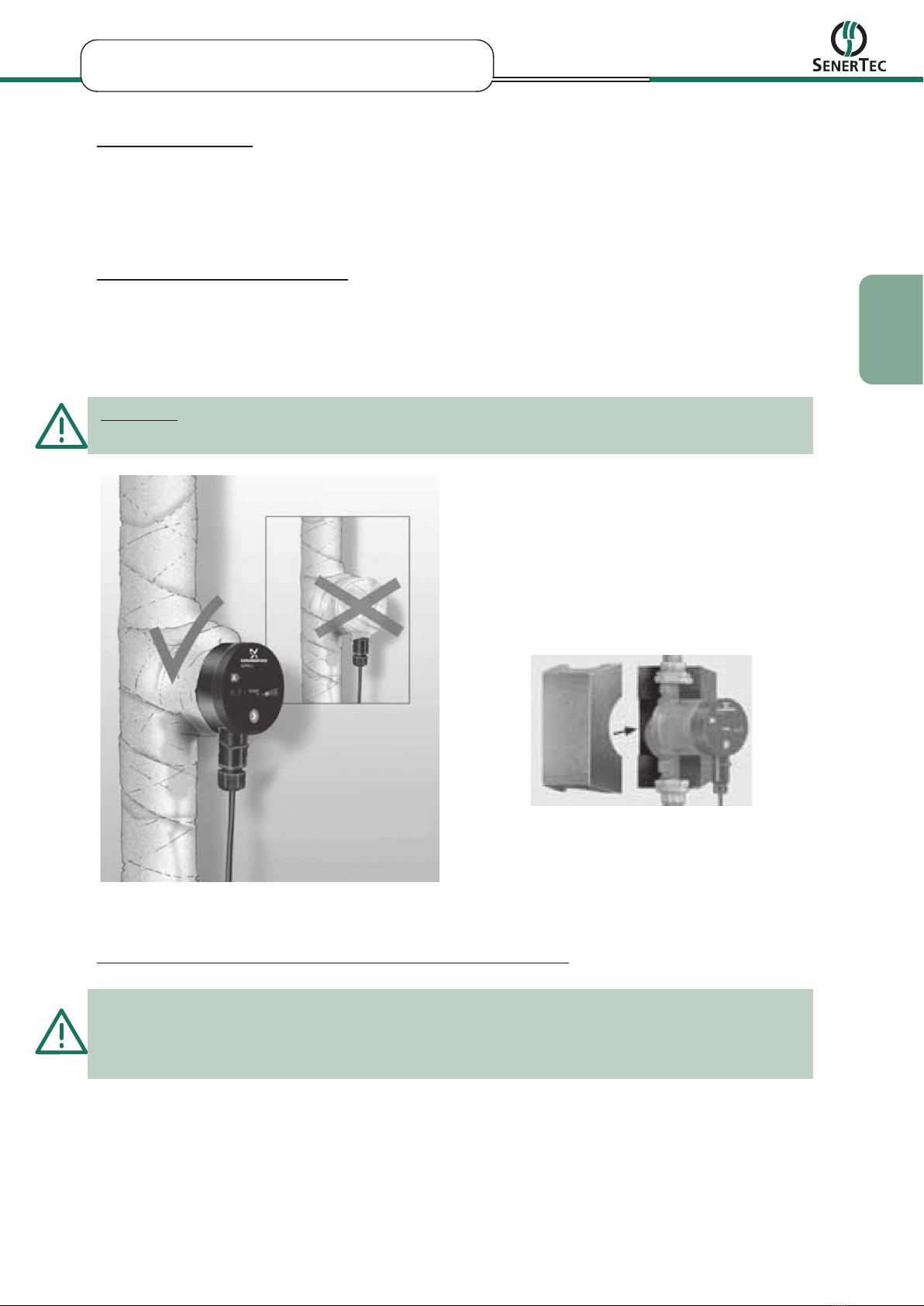
Hydraulische Einbindung
Die Montage- und Betriebsanleitung des Pumpen-
herstellers ist zu beachten!
Pumpenverschraubungen von der Pumpe lösen
und in die Rohrleitungen eindichten.
Wichtig:
Die farblich markierte Pumpenverschraubung
ist, zur Aufnahme des Thermostats, modifiziert
und muss auf der Pumpensaugseite montiert
werden.
Thermostat und Flachdichtung in die modifizier-
te Verschraubung einsetzen. Auf korrekten Sitz
der Gummidichtung achten. (Bild 1 und 2)
Pumpe einsetzen, Flachdichtung in die druck-
seitige Verschraubungen einlegen und Pumpe
befestigen.
Wichtig:
Bei Mehrmodulanlagen ist die Absperrung im Ring-
leitungskurzschluss im Regelfall zu schließen.
Pumpeneinstellungen
Die Montage- und Betriebsanleitung des Pumpen-
herstellers ist zu beachten!
Kontrolle des Ausliefer - und Betriebszustands:
Förderhöhe: Einstellung PP2
(Bild 3)
Änderung der Förderhöhe:
Förderhöhe verringern (Einstellung PP1)
Grund:
- Vorlauftemperatur wird nicht erreicht
- Geräusche in der Thermostatpumpe
Förderhöhe vergrößern (Einstellung CP1 o. CP2)
Grund:
- Dachs(e) schaltet(n) mit Übertemperatur ab
maximale Förderhöhe: 6 Meter
Bild 1: Thermostat in modifizierter Verschraubung
Bild 2: Flachdichtung
Bild 3: Übersicht der Einstellungen
Meldeleuchte
"POWER ON"
Leuchtfelder zur
Pumpeneinstellung
Drucktaste zur
Auswahl der Pum-
peneinstellung

6
deutsch
DE
Art. Nr.: 09/4798.214.004 © Änderungen und Irrtum vorbehalten
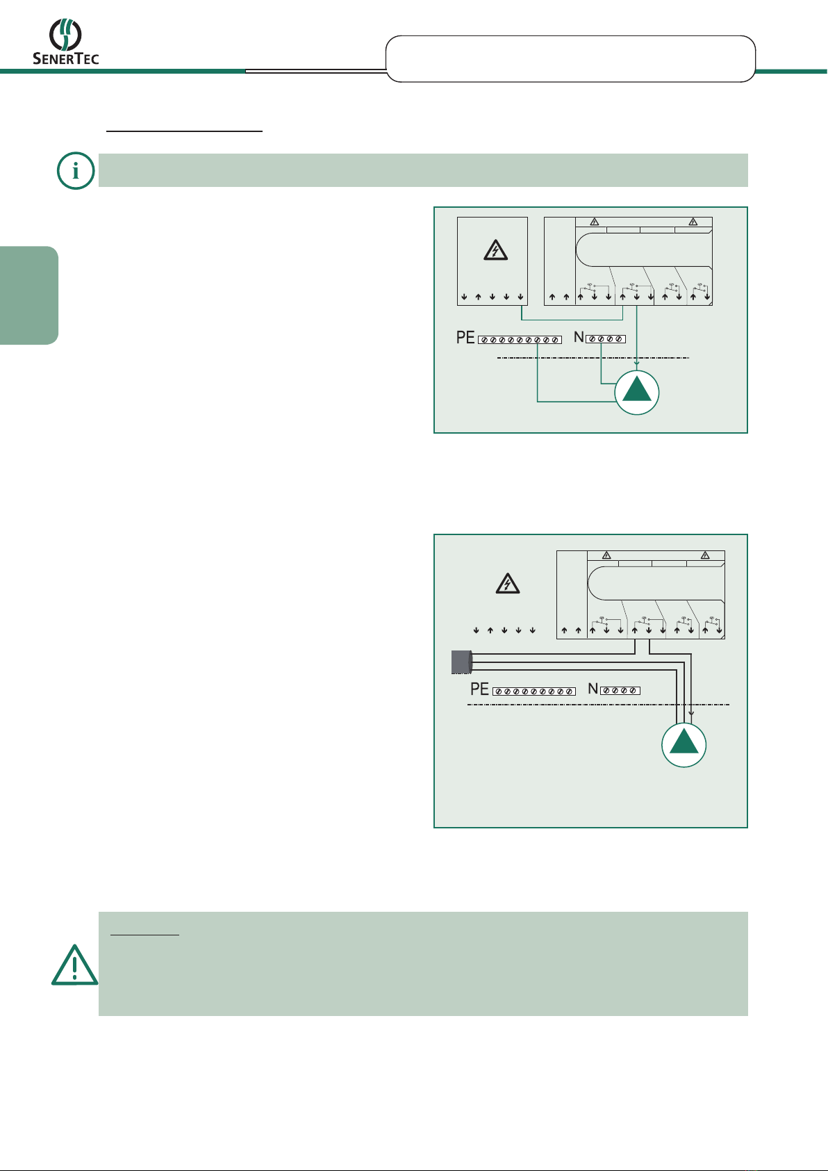
X6 Fremdspannung
F11 4A/T F14 4A/TF13 4A/TF12 4A/T
Freigabe
Wärmeerz.
prog.
Ausgang 1 Wartung Störung
Rückm.1, hoher Sollw.
Rückm.2, prog.
230V AC
1 12
X5 Aktoren extern
230V AC
Ausgang Si-Kette
Phase L1
UP Vordruck 2. WE
Öl-/Gasförderpumpe
Eingang Si-Kette
51
Elektrischer Anschluss
Die Montage- und Betriebsanleitung des Pumpenherstellers ist zu beachten!
nicht belegt
elektrischer Anschluss (MSR1) der
Thermostatpumpe bei Einmodulanlagen
Thermostatpumpe 1
Thermostatpumpe 2
externe
Versorgungsspannung
N
PE
N
PE
K2
K6
K5
K4
K3
K1
MSR1
Leitregler (L0)
X2/2
MSR1
Modul 1 (M1)
X2/2
MSR1
Modul 2 (M2)
X2/2
MSR1
Modul 3 (M3)
X2/2
MSR1
Modul 4 (M4)
X2/2
MSR1
Modul 5 (M5)
X2/2
K1
K2
K3
K4
K5
K6
N
Einzelanlagen (MSR1)
sw: Regleranschlussfeld X2/2
bl: N- Anschlussklemme
gn/ge: PE-Anschlussklemme
Einzelanlagen (MSR2)
sw: Regleranschlussfeld X6/8*
bl: N- Anschlussklemme
gn/ge: PE-Anschlussklemme
* Brücke von X5/5 auf X6/6
X6 Fremdspannung
F11 4A/T F14 4A/TF13 4A/TF12 4A/T
Freigabe
Wärmeerz.
prog.
Ausgang 1 Wartung Störung
Rückm.1, hoher Sollw.
Rückm.2, prog.
230V AC
1 12
X5 Aktoren extern
230V AC
Ausgang Si-Kette
Phase L1
UP Vordruck 2. WE
Öl-/Gasförderpumpe
Eingang Si-Kette
51
elektrischer Anschluss (MSR2) der
Thermostatpumpe bei Einmodulanlagen
Mehrmodulbetrieb (MSR1) Mehrmodulbetrieb (MSR2)
elektrischer Anschluss (MSR2) der
Thermostatpumpe(n) bei Mehrmodulanlagen bei L1,
M4, M7, M10
elektrischer Anschluss (MSR1) der
Thermostatpumpe(n) bei Mehrmodulanlagen
Wichtig:
Die externe Versorgungsspannung für die Thermostatpumpe ist bei Mehrmodulbetrieb erforderlich, damit
bei Wartung des Leitreglers die anderen Module weiterbetrieben werden können.
Werden Verbraucher durch eine externe Versorgungsspannung versorgt, muss auch auf einen korrekten
Anschluss des Neutralleiters geachtet werden. Es existieren dann 2 unterschiedliche Neutralleiter, die
nicht miteinander verbunden werden dürfen!
* Bei Mehrmodultechnik ist die Thermostatpumpe an eine externe
Spannungsversorgung anzuschließen. Eine Abschaltung des Reglers
am Hauptschalter würde sonst auch die Thermostatpumpe abschalten
und somit ein Weiterlaufen der anderen Module wegen Übertemperatur
verhindern.
externe Spannungsversorgung
PE
N
L
7
deutsch
DE
Art. Nr.: 09/4798.214.004 © Änderungen und Irrtum vorbehalten
optional:
Reglereinstellungen
Die notwendigen Reglereinstellungen zur Thermostatpumpenfunktion sind detailliert in der Bedien- und
Einstellanleitung zum MSR1 bzw. MSR2 sowie in der Montageanleitung zum Dachs beschrieben!
Isolieren des Pumpengehäuses
Über das Pumpengehäuse und die Rohrleitungen geht Wärme verloren. Diese Wärmeverluste sollten
durch Isolierung des Pumpengehäuses und der Rohrleitung reduziert werden.
Optional kann die Pumpe mit einer Wärmedämmschale für das Pumpengehäuse erworben werden.
Wichtig:
Der Klemmenkasten sowie das Bedienfeld darf nicht abgedeckt bzw. isoliert werden!
Wichtiger Hinweis zur Schalthäufigkeit der Pumpe
Gemäß Belastungsspezifikation des Pumpenherstellers liegt die Anzahl der zulässigen Ein/Aus-Schalt-
vorgänge für die Alpha 2 L bei maximal 5x pro Stunde. Im Nennbetrieb ist die Schalthäufigkeit der Pumpe
unkritisch. Häufiges manuelles Ein/Aus-Schalten ist daher zu vermeiden. Vor dem Wiedereinschalten sind
mindestens 5 Minuten zu warten.

8
english
Art. No.: 09/4798.214.004 © changes and errors excepted
GB
Safety
During assembly, commissioning and maintenance the relevant safety regulations must be observed.
This symbol is placed in front of all important safety instructions. Follow these in order to prevent
danger and damage to persons and material.
Safety
General Instructions
EC-Conformity and national regulations, directives and standards
Our Dachs-products with CE-mark are developed and manufactured pursuant to the current EC-directives
effective at the date of inspection. The manufacturer of this product confirms this by an EC-declaration of
conformity and by marking the product with the CE-mark.
Equipment, which is subject to the conditions of the EC-gas installations directive, is checked and certified
by accredited laboratories, identifiable by indicating their ID-number besides the CE-mark.
In most countries there are no harmonised EU-directives and regulations for the installation and com-
missioning of equipment within the building. With commissioning of Dachs-products national regulations,
directives and standards have to be considered by the responsible installation company.

Art. No.: 09/4798.214.004 © changes and errors excepted
9
english
GB
Areas of application
The thermostatic pump is employed mainly in:
Single module systems with hot water cylinders where a booster pump is required
(e.g. long pipe runs, system separation, heat meters).
Multi-module systems with hot water cylinders (up to 3 Dachses per pump thermostat), for feeding the
cylinder with hot water at approx. 70-80 °C in order to maintain the cylinder stratification.
Scope of Delivery
Flow rate regulated pump
Pressure side threaded connection:
(1 1/4" external thread incl. flat seal)
Intake side threaded connection:
(1 1/4" external thread, modified to accept thermostat incl. flat seal)
Installed length 180 mm
Pressure head: 1.5 m at 3 m³/h (3 Dachses)
Thermostat (70 °C)
2 m connecting cable
Brief description
Single and multi-module systems with hot water cylinders, whose interconnections between Dachs and
water cylinder exhibit a resistance of more than 20 mbar, require a circulation pump in the interconnecting
circuit (see system schematics 1 and 3). If a standard heating pump without temperature or flow rate
regulation were used, it would not be possible to achieve stratification in the hot water cylinder.
The Dachs thermostatic pump solves this problem. A thermostat incorporated into the pump feed regulates
the flow temperature to the hot water cylinder to approx. 70-80 °C. The electronically-regulated heating
pump adapts to the required flow rate by means of differential pressure control and thus saves energy
costs during partial load operation.
The flow temperature is held constant by the thermostatic pump and the flow rate is automatically adapted
to suit.
It is suitable for 1 to 3 Dachses in a single circuit. Further Dachses can be connected to the hot water
cylinder with a second circuit and a second pump (see system schematic 4).
buffer
vessel
System schematic 1: Single module system
System schematic 2: System separation
buffer
vessel
10
english
Art. No.: 09/4798.214.004 © changes and errors excepted
GB
buffer
vessel
L0
M1
M2
L1 /
(Master controller)
M2 /
M3 /
1)
buffer
vessel
L0
M1
M2
M3
M4
M5
L1 /
(Master controller)
M2 /
M3 /
M4 /
M5 /
M6 /
1)
1)
System schematic 4: Multi-module system (more than 3 Dachses)
System schematic 3: Multi-module system (up to 3 Dachses)
All hydraulic circuit diagrams are shown in simplified form, with only the components pertaining to the
thermostatic pump. Other shut-off valves, expansion tanks, etc., are omitted.
1) The shut-off valves in the ring circuit bypass are normally closed.
2) Place thermostatic pump as near to the Dachs as possible, so that the thermostat responds quickly.
Module designation
for MSR2: black
for MSR1: grey
Module designation
for MSR2: black
for MSR1: grey

Art. No.: 09/4798.214.004 © changes and errors excepted
11
english
GB
Hydraulic connections
The pump manufacturer's installation and
operating instructions must be observed!
Unfasten the couplings from the pump and fit
them to the pies.
Important:
The colour-coded pump coupling has been modi-
fied to accept the thermostat and must be fitted on
the inlet side of the pump.
Insert the thermostat and flat seal into the
modified coupling. Make sure the rubber seal
is seated correctly. (Figures 1 and 2).
Connect the pump, insert the flat seal into the
pressure-side coupling and secure the pump.
Important:
In multi-module systems, the shut-off valve in the
ring circuit bypass must normally be closed.
Pump settings
The pump manufacturer's installation and
operating instructions must be observed!
Check of delivery and operating state:
Pressure head: Settings PP2
(Figure 3)
Altering the pressure head:
Reduce pressure head
(Settings PP1)
Reason:
- Flow temperature not achieved
- Noises in the thermostatic pump
Increase pressure head
(Settings CP1 or CP2)
Reason:
- Dachs(es) switch off with overtemperature
maximum pressure head 6m
Figure 1: Thermostat in modified screw coupling
Figure 2: Flat seal
Figure 3: overview of the settings
Push-button for selection
of pump setting
"POWER ON" indicator
light
Light fields indica-
ting the pump setting
12
english
Art. No.: 09/4798.214.004 © changes and errors excepted
GB
Electrical connection
The pump manufacturer's installation and operating instructions must be observed!
Single systems (MSR 2)
black: Controller terminal strip X6/8*
blue: Neutral terminal
green/yellow: PE terminal
* Phase L1 (Link from X5/5 to X6/6)
X5/4
X6
X5 230V AC
F11 4A/T F14 4A/TF13 4A/TF12 4A/T
X6/3-5 X6/6-8 X6/9-10 X6/11-12
X6/1
X6/1
X5/1
230V AC
X5/5
X5/3
X5/2
151 12
X5/4
X6
X5 230V AC
F11 4A/T F14 4A/TF13 4A/TF12 4A/T
X6/3-5 X6/6-8 X6/9-10 X6/11-12
X6/1
X6/1
X5/1
230V AC
X5/5
X5/3
X5/2
151 12
Figure 5: Electrical connection (MSR2) of the
thermostatic pump in single module systems
Multi-module operation (MSR 2)
Figure 6: Electrical connection (MSR2) of the
thermostatic pump(s) in multi-module systems
at
L1, M4, M7, M10
Important:
The external supply voltage is important for multi-module operation, so that the other modules can continue
to be operated while the master controller is being serviced.
If consumers are supplied with external power supply, the correct connection of the neutral conductor has
to be observed. In this case, there exist two different neutral conductors that may not be interconnected.
* in the multi-module arrangement, the power for the thermostatic pump
must be sourced externally. Switching off the controller at the main switch
would also switch off the thermostatic pump and thus prevent further
operation of the other modules, owing to overtemperature.
External power supply
PE
N
L
Art. No.: 09/4798.214.004 © changes and errors excepted
13
english
GB
Controller Settings
The necessary controller settings for thermostatic pump functioning are described in detail in the operating
and adjustment manual for the MSR1 and MSR2, as well as in the Dachs installation manual.
optional:
Isolation of the pump housing
Through the pump housing and the piping heat gets lost. This heat losses are to be reduced by isolating
the pump housing and the piping.
Optionally, the pump can be acquired with an insulating shell for the pump housing.
Important:
Do not insulate the terminal box or cover the control panel.
Important indication to the switch frequency of the pump
In accordance with the load specification of the pumping manufacturer the number of the permissible ac-
tivating and deactivating procedures for the alpha 2 L is maximally 5 times per hour. Normally the switch
frequency of the pump is lower than permissible. Therefore, the frequent manual switch-on/-off is to be
avoided. Before switching on again at least 5 minutes are to be waited.
14
itAliAno
N. art.: 09/4798.214.004 © Con riserva di modifiche e correzioni
IT
Sicurezza
Durante il montaggio, la messa in funzione e la manutenzione attenersi alle disposizioni di sicurezza
contenute nelle norme EN, UNI, CEI e ISPESL, ed alle prescrizioni del distribuitore di energia elettrica
per l’allacciamento in parallelo alla rete pubblica.
Tutte le indicazioni relative alla sicurezza sono contrassegnate da questo simbolo. Attenersi a tali
indicazioni per evitare pericolo e eventuali danni a cose o persone.
Sicurezza
Avvertenze generali
Conformità CE e prescrizioni, norme e direttive nazionali
Le unità e gli accessori Dachs marchiati CE sono progettati e costruiti secondo le direttive CEE in vigore
al momento delle prove di tipo. Il costruttore certifica quanto sopra con la dichiarazione di conformità e
con il marchio CE applicato ai prodotti.
I dispositivi soggetti alla direttiva gas sono testati e certificati da un ente accreditato, come si desume
dall’indicazione del numero di identificazione dell’organismo accanto al marchio CE.
Nella maggior parte dei paesi non esistono prescrizioni e norme CE armonizzate per l’installazione e la
messa in funzione degli impianti all’interno degli edifici. Per l’installazione dei prodotti Dachs è quindi com-
pito della società responsabile dell’installazione stessa il rispetto di tutte le prescrizioni, norme e direttive
vigenti nella nazione specifica.

N. art.: 09/4798.214.004 © Con riserva di modifiche e correzioni
15
itAliAno
IT
Campi di applicazione
La pompa termostatica viene montata in:
impianti con modulo singolo con memoria tampone, nel caso si richieda una pompa con pressione
all'entrata del regolatore (ad es. grandi impianti di conduzione, interruzione di sistema, contatore quantità
di calore).
impianti plurimodulari con memoria tampone (fino a 3 Dachs per termostato pompa)
rifornire la memoria tampone con ca. 70-80 °C acqua calda, in modo da garantire la stratificazione della
memoria.
Fornitura
Pompa con flusso regolare
Chiusura a vite lato di mandata:
(1 1/4" AG incl. guarnizione piatta)
chiusura a vite lato di ritorno:
(1 1/4" AG, modificato per registrazione termostato incl. guarnizione piatta)
Lunghezza: 180 mm
Prevalenza: 1,5 m in 3 m³/h (3 Dachs)
Termostato (70 °C)
Cavo di allacciamento 2 m
Breve descrizione
Impianti plurimodulari o con modulo singolo con memoria tampone, le cui linee di allacciamento tra Dachs e
memoria tampone presentano una resistenza superiore a 20 mbar, necessitano di una pompa di circolazione
nel circuito di collegamento (vedere gli schemi di installazione 1 e 3). Se si dovesse inserire una pompa di
riscaldamento standard senza regolazione di flusso e di temperatura, non si potrebbe raggiungere alcuna
stratificazione nella memoria tampone.
La pompa termostatica Dachs svolge questa funzione. Un termostato integrato all'ingresso della pompa regola
la temperatura di mandata sulla memoria tampone a circa 70-80 °C. La pompa di riscaldamento regolata
elettronicamente si adatta alla quantità di flusso necessario tramite la regolazione di pressione differenziata
risparmiando costi di energia elettrica nel funzionamento di carico parziale.
Con la pompa termostatica viene regolata costantemente la temperatura di mandata adattando
automaticamente la prestazione.
È adatta in un circuito da 1 a 3 Dachs. Altri Dachs possono essere collegati alla memoria tampone mediante
un secondo circuito e una seconda pompa termostatica (vedere schema di installazione 4).
Accumu-
latore
Schema di installazione 1: impianto con
modulo singolo
Accumu-
latore
Schema di installazione 2: interruzione di
sistema

16
itAliAno
N. art.: 09/4798.214.004 © Con riserva di modifiche e correzioni
IT
Accumu-
latore
L0
M1
M2
L1 /
(Master)
M2 /
M3 /
1)
Accumu-
latore
L0
M1
M2
M3
M4
M5
L1 /
(Master)
M2 /
M3 /
M4 /
M5 /
M6 /
1)
1)
Schema di installazione 4: impianto plurimodulare (più di 3 Dachs)
Schema di installazione 3: impianto plurimodulare (fino a 3 Dachs)
Tutti gli schemi di circuito idraulici sono rappresentati come schemi di circuito principali, salvo l'aggiunta
degli elementi costitutivi della pompa termostatica. Mancano altri blocchi, recipienti di espansione , ecc..
1) I blocchi nel cortocircuito su circuito ad anello generalmente sono chiusi.
2) Collocare la pompa termostatica il più vicino possibile al Dachs affinché il termostato risponda rapido.
Indicazione
modulare
per MSR2: nero
per MSR1: grigio
Indicazione
modulare
per MSR2: nero
per MSR1: grigio

N. art.: 09/4798.214.004 © Con riserva di modifiche e correzioni
17
itAliAno
IT
Allacciamento idraulico
Osservare le Istruzioni per il montaggio e il
funzionamento fornite dal produttore delle pompe!
Allentare le viti delle pompe e sigillare
ermeticamente le tubature.
Importante:
Al montaggio del termostato la chiusura a vite delle pom-
pe, contrassegnata con dei colori, è modificata e deve
essere montata sul lato aspirante della pompa.
Inserire il termostato e la guarnizione piatta nella
chiusura a vite modificata. Prestare attenzione
al corretto posizionamento della guarnizione di
gomma. (Figura 1 e 2)
Introdurre la pompa, inserire la guarnizione
piatta nelle chiusure a vite sul lato di mandata
e fissare la pompa.
Importante:
Generalmente negli impianti plurimodulari il blocco
nel cortocircuito su circuito ad anello deve essere
chiuso.
Regolazioni delle pompe
Osservare le Istruzioni per il montaggio e il
funzionamento fornite dal produttore delle pompe!
Controllo dello stato di esercizio e di consegna:
Frevalenza: impostazione PP2
(Figura 3)
Modifica della prevalenza:
Diminuire la prevalenza
(impostazione PP1)
causa:
-
non viene raggiunta la temperatura di mandata
- rumori nella pompa termostatica
Aumentare la prevalenza
(impostazione PP1 oPP2)
causa:
- Dachs si spegne/ i Dachs si spengono con
surriscaldamento
prevalenza massima 6m
Figura 1: termostato nell'avvitamento modificato
Figura 2: guarnizione piatta
Figura 3: Panoramica delle Impostazioni
La spia luminosa
"POWER ON"
Segmenti
luminosi indicanti
l'impostazione della
pompa
Pulsante per la selezione
dell'impostazione della
pompa

18
itAliAno
N. art.: 09/4798.214.004 © Con riserva di modifiche e correzioni
IT
Collegamento elettrico
Osservare le Istruzioni per il montaggio e il funzionamento fornite dal produttore delle pompe!
Impianti singoli (MSR 2)
ne: campo di regolazione X6/8
bl: morsetto d'attacco N
ve/gia: morsetto d'attacco PE
* fase L1 (ponte da X5/5 a X6/6)
X5/4
X6
X5 230V AC
F11 4A/T F14 4A/TF13 4A/TF12 4A/T
X6/3-5 X6/6-8 X6/9-10 X6/11-12
X6/1
X6/1
X5/1
230V AC
X5/5
X5/3
X5/2
151 12
Figura 7: collegamento elettrico (MSR2) della
pompa termostatica in impianti con
modulo singolo
Figura 8: collegamento elettrico (MSR2) della
pompa termostatica/ delle pompe
termostatiche in impianti plurimodulari a
L1, M4, M7, M10
Importante:
la tensione di alimentazione esterna è importante nel funzionamento plurimodulare, in quanto nella ma-
nutenzione del regolatore principale possono essere messi in funzione gli altri moduli.
Se i comsumatori sono alimentati con tensione esterna, la corretta connessione del conduttore neutro
deve essere rispettato. In questo caso, esistono due diversi conduttori di neutro che non devono essere
interconnessi.
Impianti plurimodulari (MSR 2)
X5/4
X6
X5 230V AC
F11 4A/T F14 4A/TF13 4A/TF12 4A/T
X6/3-5 X6/6-8 X6/9-10 X6/11-12
X6/1
X6/1
X5/1
230V AC
X5/5
X5/3
X5/2
151 12
* Nella tecnica plurimodulare, la pompa termostatica deve essere
alimentata externamente con tensione. Lo spegnimento del regolatore
dall’interruttore principale comporterebbe lo spegnimento della pompa
termostatica stessa e quindi impediribbe un ulteriore funzionamento
degli altri moduli a causa del surriscaldamento.
Alimentazione di tensione
PE
N
L

N. art.: 09/4798.214.004 © Con riserva di modifiche e correzioni
19
itAliAno
IT
Impostazioni del regolatore
Le impostazioni necessarie del regolatore per il funzionamento delle pompe termostatiche sono descritte dettagli-
atamente nelle Istruzioni di installazione e utilizzo del MSR1 o MSR2 e nelle Istruzioni di montaggio del Dachs!
facoltativo:
Isolazione del corpo della pompa
Attraverso il corpo della pompa e la tubazione va perduto del calore. Queste perdite di calore devono
essere ridotte a mezzo di isolare il corpo della pompa e la tubazione.
Facoltativamente, è possibile acquistare la pompa insieme a un guscio termoisolante per il corpo della
pompa.
Importante:
Non isolare la morsettiera e non coprire il pannello di controllo.
Nota importante sulla frequenza di collegamento della pompa
Secondo la specificazione di carico del produttore della pompa il numero di procedure di attivazione/
disattivazione ammesso per l'Alpha 2 L è al massimo 5 volte all'ora. Nel caso normale, la frequenza di
attivazione/disattivazione della pompa è minore di ammesso. L’attivazione/disattivazione manuale frequente
è da evitare perciò. È da aspettare come minimo 5 minuti prima di riattivare.
20
espAÑol
Nº de ref.: 09/4798.214.004 © Salvo error. Sujeto a modificaciones.
ES
Seguridad
Durante el montaje, la puesta en marcha y el mantenimiento es preciso observar las normativas de se-
guridad DIN, DVGW, VDE, TAB y de la UE.
Este símbolo aparece delante de todas las indicaciones de seguridad importantes. Siga dichas
indicaciones para descartar peligros y daños en las personas y bienes materiales.
Seguridad
Indicaciones generales
Conformidad CE, normas, reglamentos y directrices nacionales
Los productos Dachs con distintivo CE han sido desarrollados y fabricados de acuerdo con las directrices
CE vigentes en el momento de su comprobación. El fabricante del producto así lo confirma mediante la
declaración de conformidad CE y el distintivo CE en el producto.
Los dispositivos sujetos a la directriz CE relativa a aparatos de gas se comprueban y certifican mediante
centros acreditados para tal fin. Esto se reconoce por el distintivo CE y el número de identificación del
centro en cuestión.
En la mayoría de países no existen directrices CE ni regulaciones armonizadas para la instalación y pu-
esta en marcha de aparatos en interiores. Por consiguiente, la empresa encargada de instalar productos
Dachs deberá tener en cuenta las normas, reglamentos y directrices vigentes del país en cuestión.
This manual suits for next models
1
Table of contents
Languages:
Popular Water Pump manuals by other brands

IMP PUMPS
IMP PUMPS NMT 40 Installation and operating manual

Alfalaval
Alfalaval LKH Prime UltraPure instruction manual

i-MO
i-MO OptiLine ACG8 Original operating manual

Alfalaval
Alfalaval SRU series instruction manual

Little Giant
Little Giant SPBS manual

FLORABEST
FLORABEST FTS 1100 C3 Translation of the original instructions


BUSCH
BUSCH COBRA BC 1200 A instruction manual

Scheppach
Scheppach HWW1000 Translation of original instruction manual

moyno
moyno 1000 Service manual

Liquiflo
Liquiflo H-Series Installation, operation & maintenance manual

TapFlo
TapFlo Steinle Filter Press Pump Series Original instruction

Wilo
Wilo Stratos PARA-C Installation and operating instructions