*Teflon is a registered trademark of E.I. duPont de Nemours & Co., Inc.
2
and other metallic parts in contact with the material
being pumped.
The third letter indicates the material of the stator. It
identifies only the stator material and not that of the tube
in which the stator is placed. The tube, a non-wetted
part, is always alloy steel.
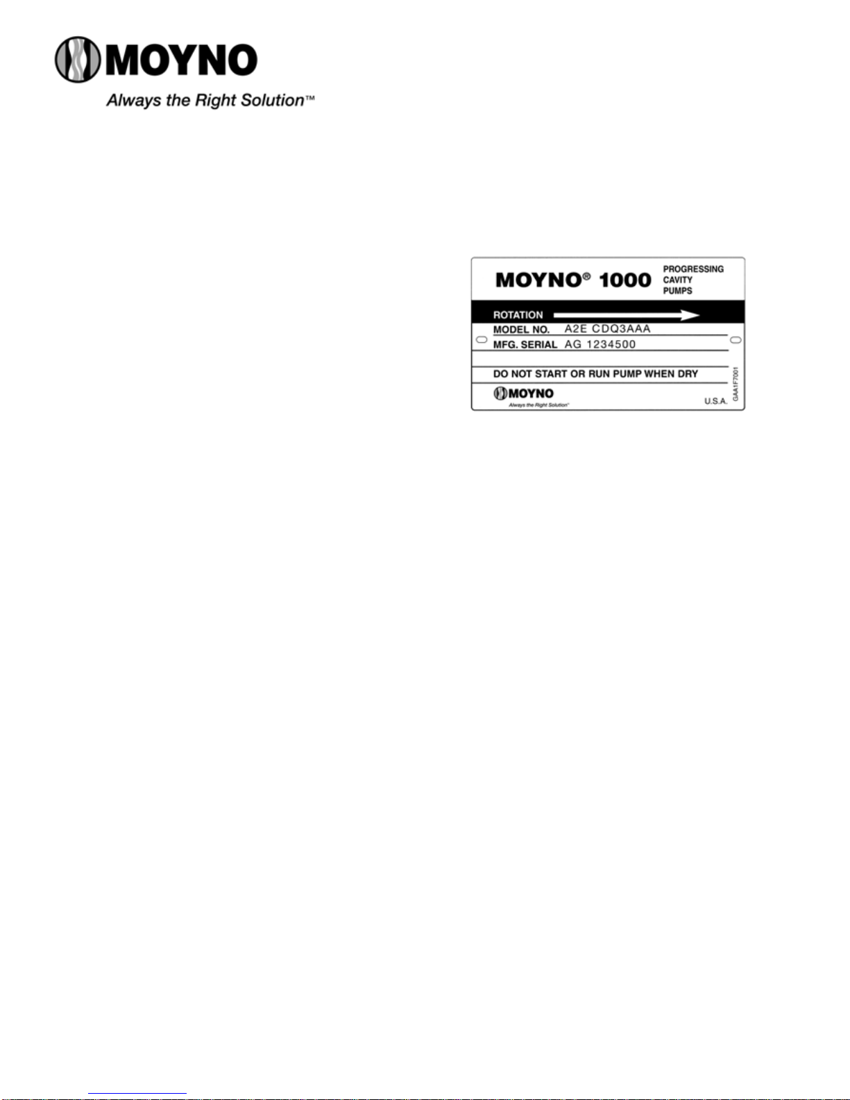
A typical designation such as the CDQ used in our
example would result in the following:
C = Cast iron suction chamber
D = Hardened alloy steel internals including drive
shaft, connecting rod, pins, and rotor
Q = Nitrile (NBR) stator (70 durometer hardness)
The following letters identify the materials used in
standard construction:
C = Cast iron
D = Hardened alloy steel
S = Stainless steel, Type 316
Q = Nitrile (NBR), 70 durometer hardness
B = EPDM
F = Fluoroelastomer
The next position is a number identifying the current
pump revision, this manual corresponds to revision 3.
The last three letters indicate the trim code and
denote internal variations in a pump. The first letter
identifies sealing variations. The second letter indicates
internal variations. The third letter indicates rotor
variations.
A typical trim code is AAA, designating the following:
A = Standard black packing
A = Standard plated shaft
A = Standard size chrome-plated rotor
The variations available are:
Sealing:
A – Standard black packing
C – Teflon7 white packing (not food grade)
S – single mechanical seal
D – Double mechanical seal
Internal variations:
A – Standard plated shaft
B – Non-plated shaft
P – Two-piece shaft or pinned close coupled
Rotor variations:
A – Standard plated rotor
B – Non-plated rotor
C – Standard undersize
E – Standard oversize
X – Special to order
2-1. INSTALLATION
2-2. GENERAL
Accessibility to the pump and adequate clearance should
be prime considerations in any installation. Enough space
should surround the unit so that maintenance can be
performed with ease.
2-3. PIPING
2-4. Suction piping should be as short as possible.
Normally, the suction line should be the same diameter as
the pump suction; however, conditions such as high
viscosity or required minimum flow velocities may dictate
otherwise. Long-sweep 90 degree elbows or 45 degree
elbows should be used instead of the standard elbow.
Avoid using suction piping loops which trap air.
2-5. Discharge piping diameter should generally be as
large as the discharge port unless fluid conditions indicate
otherwise.
An easily-removable section of piping, at least twice as
long as the stator, should be mated to the discharge port.
This will allow the rotor and stator to be removed without
having to remove the complete pump from the base.
2-6. FOUNDATION
For maximum pump-driver unit life, each unit should be
mounted on a strong steel baseplate. The baseplate should
be mounted on a firm foundation. The motors should be
supported on close-coupled configurations above 1 HP.
2-7. SHAFT ALIGNMENT
After the base has been bolted down to the foundation,
check the following conditions:
2-8. Coupling connected units. Be sure that the pump
and drive shafts are aligned before the coupling is
connected. Care should be exercised to ensure that all
components are level and mounted in a direct line.
Check the gap between coupling halves (refer to coupling
manufacture’s recommendations). Adjustment can usually
be made by loosening the mounting bolts on either the
pump or driver and moving the loosened component into
alignment with the fixed component. Do not use a hammer!
On couplings with equal diameter hubs, it may be helpful to
lay a straight edge across the coupling halves to check
alignment.
2-9. Belt drive units. Be sure that sheaves or sprockets
are in alignment. Check belts for proper tension. Tension
requirements will vary with type of belt, center distances,
and belt speeds. Consult belt manufacturer for specific
recommendations.