Senis 3MH6 User manual

3MH6 Teslameter
User Manual
Ref.No.: OM.200.3MH6 TESLAMETER
Document Re ision: 2.0
Software Version:
Android Application: 2.4.5 – 16Oct2020:1228
STM Board Firmware Version: 2.2.0
Data Acquisition Software: 3MH6 Teslameter 11.20

This Page Intentionally Blank

3MH6 TESLAMETER
Ref.No.: OM.200.3MH6_TESLAMETER
Re .2.0
Page 3/126
Specifications subject to change without notice.
The displayed information is belie ed to be accurate and reliable. Howe er, no responsibility is assumed SENIS AG for its use, nor for
any infringements of patents or other rights of third parties that may result from its use
Table of Contents
Table of Contents ......................................................................................................................................................... 3
1. SAFETY PRECAUTIONS: ............................................................................................................................................. 5
2. INTRODUCTION ......................................................................................................................................................... 7
2.1 O er iew ..................................................................................................................................................... 7
3. GENERAL DESCRIPTION ............................................................................................................................................ 8
3.1 Key Features ................................................................................................................................................ 8
3.2 Typical Applications ..................................................................................................................................... 8
3.3 Connections ................................................................................................................................................. 9
4. INSTALLATION ......................................................................................................................................................... 10
4.1 Inspection and Unpacking ......................................................................................................................... 10
4.2 Front Panel Description ............................................................................................................................. 11
4.3 Rear Panel Description .............................................................................................................................. 13
4.4 Line Input Assembly .................................................................................................................................. 14
4.5 Probe Input Connection ............................................................................................................................ 15
4.6 Probe Handling and Operation ................................................................................................................. 15
4.7 Functional Verification .............................................................................................................................. 15
5. OPERATION MANUAL ............................................................................................................................................. 16
5.1 Power-up ................................................................................................................................................... 16
5.2 Numeric Tab .............................................................................................................................................. 18
5.3 Timeplot Tab ............................................................................................................................................. 19
5.4 Histogram Tab ........................................................................................................................................... 21
5.5 3MH6 Teslameter Settings ........................................................................................................................ 24
5.5.1 Measurement Mode .............................................................................................................................. 25
5.5.2 Setup Menu ............................................................................................................................................ 32
5.5.3 BSelector ................................................................................................................................................ 67
5.5.4 Info Display ............................................................................................................................................. 70
5.6 Zeroing ...................................................................................................................................................... 74
5.7 Hold ........................................................................................................................................................... 77
5.8 Logging Measurements ............................................................................................................................. 78
5.9 Auto/Manual Range Button ...................................................................................................................... 82
6. DATA ACQUISITION SOFTWARE ............................................................................................................................. 83
6.1 Data Acquisition ........................................................................................................................................ 84
6.1.1 Range Selection ...................................................................................................................................... 85
6.1.2 Data Rate (Sampling Rate) ..................................................................................................................... 85
6.1.3 Acquisition Modes.................................................................................................................................. 86

3MH6 TESLAMETER
Ref.No.: OM.200.3MH6_TESLAMETER
Re .2.0
Page 4/126
Specifications subject to change without notice.
The displayed information is belie ed to be accurate and reliable. Howe er, no responsibility is assumed SENIS AG for its use, nor for
any infringements of patents or other rights of third parties that may result from its use
6.1.4 Sa ing and Loading Acquired Data ......................................................................................................... 87
6.1.5 Sa ing and Loading Only One Screen of the Acquired Data .................................................................. 88
6.2 Offset Zeroing ............................................................................................................................................ 88
6.3 Probe Replacement ................................................................................................................................... 90
6.3.1 Loading Probe Calibration Coefficients into De ice Using 3MH6.exe Application ................................ 91
7. MAINTENANCE ....................................................................................................................................................... 96
8. GENERAL SPECIFICATIONS ...................................................................................................................................... 97
8.1 Characteristics ........................................................................................................................................... 97
9. PROBE SPECIFICATION ............................................................................................................................................ 99
9.1 Probe I3C-03C ............................................................................................................................................ 99
9.2 Installation Manual for the 03C Hall Probe: ............................................................................................ 101
10. RECOMMENDED ACCESSORIES: ......................................................................................................................... 102
11. NOTES TO GENERAL SPECIFICATIONS:................................................................................................................ 103
12. APPENDIX – COMMUNICATION PROTOCOL OVERVIEW .................................................................................... 106
12.1 General on Communication Protocol ...................................................................................................... 106
12.2 Used Con entions and Abbre iations ..................................................................................................... 107
12.3 Commands Description ........................................................................................................................... 107
12.3.1 Calibrated/Direct Mode Commands ............................................................................................... 107
12.3.2 Broadcast Command ....................................................................................................................... 108
12.3.3 Stop Command ............................................................................................................................... 113
12.3.4 Commands for Sampling Rate Setting/Reading .............................................................................. 113
12.3.5 Commands for Measurement Range Setting/Reading ................................................................... 114
12.3.6 Command for Logger File Reading .................................................................................................. 116
12.3.7 Command for Timeplot Data Reading ............................................................................................ 116
12.3.8 Commands for Trigger Mode Setting.............................................................................................. 118
12.3.9 Commands for Zeroing and Zeroing Coefficients Reading ............................................................. 119
12.3.10 Non- olatile Memories Related Commands ................................................................................... 120
12.3.11 Help Command ............................................................................................................................... 125
3MH6 TESLAMETER
Ref.No.: OM.200.3MH6_TESLAMETER
Re .2.0
Page 5/126
Specifications subject to change without notice.
The displayed information is belie ed to be accurate and reliable. Howe er, no responsibility is assumed SENIS AG for its use, nor for
any infringements of patents or other rights of third parties that may result from its use
1. SAFETY PRECAUTIONS:
The following safety precautions must be obser ed during all phases of operation, ser ice and repair of this
equipment. Failure to comply with these precautions or with specific warnings elsewhere in this manual iolates
safety standards of design, manufacture and intended instrument use. SENIS AG assumes no liability for Customer
failure to comply with these requirements.
The Teslameter 3MH6 protects the operator and surrounding area from electric shock or burn, mechanical
hazards, excessi e temperature and spread of fire from the instrument. En ironmental conditions outside of the
conditions below may pose a hazard to the operator and surrounding area.
General Precautions
• Indoor use.
• Altitude up to 2000 meters.
• Temperature for safe operation: 5°C to 45°C (with decreased linearly of up to 50% from 30°C).
• Maximum relati e humidity: 80%
• Power supply oltage fluctuations not to exceed ±10% of the nominal oltage.
• Switch-on stabilization time: 30 minutes.
• O er oltage category II.
• Pollution degree 2.
Ground the Instrument
To minimize shock hazard, the instrument is equipped with a 3-wire AC power cable. Plug the power cable into an
appro ed three-contact electrical outlet or use a three-contact adapter with the grounding wire (green), firmly
connected to an electrical ground (safety ground) at the power outlet. The power jack and mating plug of the
power cable meet Underwriters Laboratories (UL) and International Electrotechnical Commission (IEC) safety
standards.
Do not unplug any cables while measurement is in progress. Always switch off the Teslameter prior to unplugging
the cables.
Ventilation
The instrument has entilation holes in its bottom side. Do not block these holes when the instrument is
operating.
Keep the de ice always in horizontal position (also during the transport).
3MH6 TESLAMETER
Ref.No.: OM.200.3MH6_TESLAMETER
Re .2.0
Page 6/126
Specifications subject to change without notice.
The displayed information is belie ed to be accurate and reliable. Howe er, no responsibility is assumed SENIS AG for its use, nor for
any infringements of patents or other rights of third parties that may result from its use
Do Not Operate in an Explosi e or Electromagnetic Atmosphere
Do not subject the de ice to impacts. Do not operate the instrument in the presence of flammable gases or
fumes. Operation of any electrical instrument in such an en ironment constitutes a definite safety hazard.
During operation, remo e magnetic sources from the icinity of the de ice. Only magnets under the test are
allowed.
Keep Away from Li e Circuits
Operating personnel must not remo e instrument co ers. Refer component replacement and internal
adjustments to qualified maintenance personnel. Do not replace components with power cable connected. To
a oid injuries, always disconnect power and discharge circuits before touching them.
Do Not Substitute Parts or Modify Instrument
If you disco er any abnormalities, before or during operation, stop using the de ice and inform the manufacturer.
Do not install, substitute parts or perform any unauthorized modification to the instrument. Return the
instrument to an authorized SENIS AG representati e for ser ice and repair to ensure that safety features are
maintained.
Hall Probe and probe holder are fragile. Protect both from impacts during operation and when not in use.
Do not apply undue force to plugs, cables or the Hall probes.
Cleaning
Do not submerge instrument. Clean only with a damp cloth and mild detergent (exterior only).

3MH6 TESLAMETER
Ref.No.: OM.200.3MH6_TESLAMETER
Re .2.0
Page 7/126
Specifications subject to change without notice.
The displayed information is belie ed to be accurate and reliable. Howe er, no responsibility is assumed SENIS AG for its use, nor for
any infringements of patents or other rights of third parties that may result from its use
2. INTRODUCTION
2.1 O er iew
The 3MH6 Digital Low-Noise Teslameter is a high-performance magnetic field measuring instrument based on the
Hall-effect magnetic-field-to- oltage transducer with a high-le el, temperature compensated analog output signal
for each of three components of the measured magnetic flux density components, Bx, By and Bz. The USB serial
communication ports allow automatic data acquisition by a host computer, so that users may easily integrate a
measurement routine into any measuring system using programming tools. 3MH6 incorporates a TFT LCD graphic
display for an intuiti e de ice operation and configuration, as well as for numerical and graphical measured data
isualization.
The Low Noise Digital Teslameter is a high accuracy temperature-stabilized instrument for the precise
measurement of magnetic field. The digital data correction pro ides an accuracy of better than 0.01%. The unique
SENIS single-chip integrated 3-axis Hall probe allows measuring simultaneously all three components of the
magnetic field at irtually the same spot within a 100 µm x 100 µm square, which allows measurements of
homogeneous and highly inhomogeneous magnetic fields. E en for strong magnetic fields there is no planar Hall
effect, which would lead to the cross talk between the three measurement channels. The Teslameter is therefore
suitable for the characterization of not only strong magnets, but also of ery small magnets and magnetic systems
with narrow air gaps.
Interchangeable Hall-Probes, the unique miniature 1- 2- and 3-axis probes can be connected to the 3MH6
Teslameters. The indi idually calibrated correction data of each probe are stored in the probe EEPROM as well as
in the Teslameter de ice. The calibration data are automatically loaded from the probe EEPROM when de ice is
turned on first time after the probe has been replaced. All these features allow building long term stable and
precise instruments for accurate 1-, 2- and 3-axis magnetic field mapping, magnetic field control and permanent
magnet quality inspection.

3MH6 TESLAMETER
Ref.No.: OM.200.3MH6_TESLAMETER
Re .2.0
Page 8/126
Specifications subject to change without notice.
The displayed information is belie ed to be accurate and reliable. Howe er, no responsibility is assumed SENIS AG for its use, nor for
any infringements of patents or other rights of third parties that may result from its use
3. GENERAL DESCRIPTION
3.1 Key Features
3.2 Typical Applications
• DC and AC magnetic field measurements (Frequency Bandwidth: DC – 2.5 kHz)
• Simultaneous measurements of all components of magnetic field (B
x
, B
y
and B
z
)
• High speed measurements
• Inhomogeneous magnetic fields
• Determination of the magnetic field orientation
• Magnetic field measurements in a small air gap and/or in the near proximity of the magnet surface
• Measurements of the full magnetic field range with only one Hall probe
• Mapping magnetic fields
• Characterization of undulators systems
• Current sensing
▪
DC measurement accuracy
< 100 ppm of Full Scale
▪ DC resolution
@±2
T range: 1
µT
rms
for planar and 2
µT
rms
for
perpendicular components of magnetic field
▪ Maximum measured field
▪ Calibrated ranges
Up to ±20 T
±100 mT / ±500 mT / ±2 T / ±20 T
Note: ±20 T range is currently calibrated only up to ±2 T
▪
Probe cable length
2 m (default)
▪ Easy probe replacement
Automatic loading of the probe calibration coefficients from
probe EEPROM on power-up
▪
Digital interface
USB 2.0 type B connector for data
acquisition
▪
Analog outputs
Connection to DAQ card
▪
TFT Capaciti e Touch LCD
5'', 800 x 480 pixels, 24
-
bit, white LED backlight
▪ Size W 240 x H 140 x L 260 mm
▪ Weight Ca. 3.5 kg

3MH6 TESLAMETER
Ref.No.: OM.200.3MH6_TESLAMETER
Re .2.0
Page 9/126
Specifications subject to change without notice.
The displayed information is belie ed to be accurate and reliable. Howe er, no responsibility is assumed SENIS AG for its use, nor for
any infringements of patents or other rights of third parties that may result from its use
3.3 Connections
Figure 3.1 Structure of t e Low Noise Teslameter 3MH6 wit fully integrated Hall Probe
-Module H, consisting of t e Hall Probe and t e CaH Cable
- Module E, analog and digital electronics for signal conditioning
SENIS AG
3MH6 TESLAMETER
magnetic & current measurement
Module E
Module H
Status LED
SENIS AG
3MH6 TESLAMETER
magnetic & current measurement
Touch screen
USB connector B type
|
A
A
A
LNT-T LNT-Y LNT-Z LNT-X
POWER DMOD
Probe input
Analog outputs
Power switch
Fuse
Power supply connector
Trigger input

3MH6 TESLAMETER
Ref.No.: OM.200.3MH6_TESLAMETER
Re .2.0
Page 10/126
Specifications subject to change without notice.
The displayed information is belie ed to be accurate and reliable. Howe er, no responsibility is assumed SENIS AG for its use, nor for
any infringements of patents or other rights of third parties that may result from its use
4. INSTALLATION
4.1 Inspection and Unpacking
Inspect shipping containers for external damage before opening them. Photograph any container that has
significant damage before opening it. If there is a isible damage to the contents of the container, contact the
shipping company and SENIS AG immediately, preferably within 5 days of receipt of goods. Keep all damaged
shipping materials and contents until instructed to either return or discard them.
Open the shipping container and keep the container and shipping materials until all contents ha e been
accounted for. Check off each item on the packing list as it is unpacked. Instruments themsel es may be shipped
as se eral parts.
If the instrument must be returned for recalibration, replacement or repair, a return authorization (RA) number
must be obtained from a factory representati e before it is returned.
Probes are shipped in cardboard containers and are often included in the instrument shipping carton. Please
retain the probe container for probe storage. This will help protect the delicate probes from being damaged.
Items included with 3MH6 Teslameter box:
1 3MH6 de ice
1+ 3-Axis Hall probe (I3C-03C02L)
1 3MH6 Operating Manual, Certificate of Calibration and Angular accuracy (on request)
1 Memory stick (flash memory) containing probes calibration data and PC software for interfacing with
3MH6 teslameter.
1 USB cable to connect 3MH6 de ice to your computer
1 BNC cable to connect trigger pulses
1 Power cord
1 Output cable for uncompensated analog oltage (on request)
1 Touch pen
3MH6 TESLAMETER
Ref.No.: OM.200.3MH6_TESLAMETER
Re .2.0
Page 11/126
Specifications subject to change without notice.
The displayed information is belie ed to be accurate and reliable. Howe er, no responsibility is assumed SENIS AG for its use, nor for
any infringements of patents or other rights of third parties that may result from its use
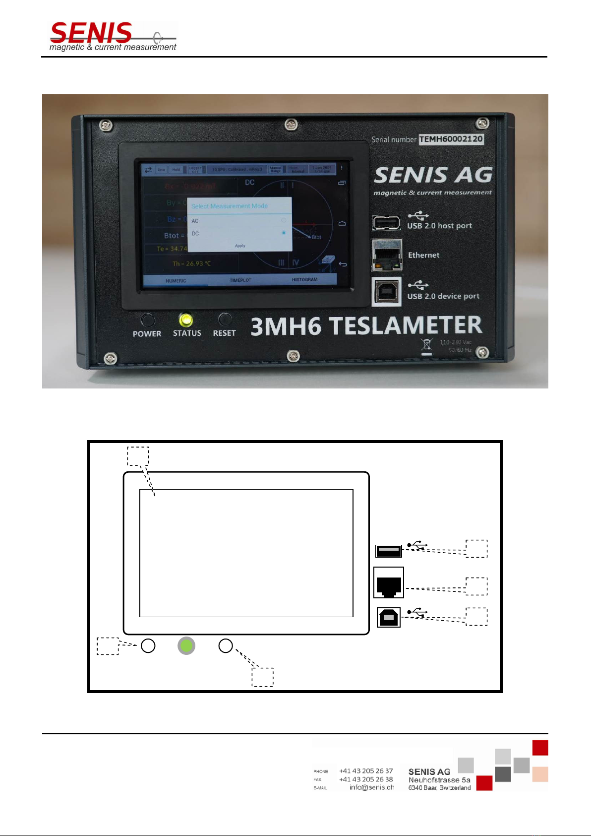
4.2 Front Panel Description
Figure 4.1 Front side p oto
Figure 4.2 Front panel view
SENIS AG
3MH6 TESLAMETER
magnetic & current measurement
Ethernet
USB 2.0 host port
USB 2.0 de ice port
1
3
4
5
STATUS
POWER
RESET
6
2

3MH6 TESLAMETER
Ref.No.: OM.200.3MH6_TESLAMETER
Re .2.0
Page 12/126
Specifications subject to change without notice.
The displayed information is belie ed to be accurate and reliable. Howe er, no responsibility is assumed SENIS AG for its use, nor for
any infringements of patents or other rights of third parties that may result from its use
1 Display
5"
TFT
Capaciti e Touch LCD
,
800x480
pixel
,
24
-
bit, White LED
Backlight, Dimensions: L120.7 x H75.8 mm
2
USB
connector
USB 2.0 Type B
connector
-
De ice port for data acquisition
3 Ethernet
RJ45 connector
-
For future use
(to be implemented in one o
f
next releases)
4 USB connector
USB 2.0 Type A connector
-
Host port for future use
(to be
implemented in one of next releases)
5 Power push button
Power push button will be implemented in one of next
releases.
6 Reset push button
Reset of the main m
icrocontroller board
. Pressing this button
results in rebooting of the Android operating system

3MH6 TESLAMETER
Ref.No.: OM.200.3MH6_TESLAMETER
Re .2.0
Page 13/126
Specifications subject to change without notice.
The displayed information is belie ed to be accurate and reliable. Howe er, no responsibility is assumed SENIS AG for its use, nor for
any infringements of patents or other rights of third parties that may result from its use
4.3 Rear Panel Description
Figure 4.3 Rear side p oto
Figure 4.4 Rear panel view
2
DMOD
S
er ice port
Trigger IN
|
0
POWER
LNT
-
Y
LNT
-
Z
LNT
-
X
LNT
-
T
1
3
4
5
6
By Analog Out
Bz Analog Out
Bx Analog Out

3MH6 TESLAMETER
Ref.No.: OM.200.3MH6_TESLAMETER
Re .2.0
Page 14/126
Specifications subject to change without notice.
The displayed information is belie ed to be accurate and reliable. Howe er, no responsibility is assumed SENIS AG for its use, nor for
any infringements of patents or other rights of third parties that may result from its use
1 Line input assembly Includes line cord inlet and instrument power switch
2 Modulator / Demodulator
board / Trigger input
Includes board for generation of digital signals necessary to
control modulation and demodulation process as well as the
trigger signal input
3 Temperature processing board
with temperature sensor input
Includes board for processing the temperature output signal
from the probe
4, 5, 6 Hall sensor processing boards
for B
x
, B
y
and B
z
Include boards for processing Hall sensor signals from the
probe
CAUTION: Make rear panel connections with the instrument powered OFF.
4.4 Line Input Assembly
Figure 4.5 Switc ed and fused inlet
1 Line Cord Input Voltage range: 88 ~ 264 VAC, Frequency range: 47 ~ 63 Hz
2 Power Switch 0-OFF / |-ON
3 Fuse Drawer 1.5 A

3MH6 TESLAMETER
Ref.No.: OM.200.3MH6_TESLAMETER
Re .2.0
Page 15/126
Specifications subject to change without notice.
The displayed information is belie ed to be accurate and reliable. Howe er, no responsibility is assumed SENIS AG for its use, nor for
any infringements of patents or other rights of third parties that may result from its use
4.5 Probe Input Connection
WARNING: Probes used with the teslameter ha e conducti e parts. Ne er expose the probe near li e oltage.
Personal injury and damage to the instrument may result.
The SENIS probe plugs into the 22 pin LEMO connector on the rear panel. Align the probe connector with the rear
panel connector and push straight in to a oid bending the pins.
4.6 Probe Handling and Operation
To a oid damages and for the best results during measurements, a number of handling and accuracy
requirements must be fulfilled.
Although e ery attempt has been made to make the probes as robust as possible, they are still fragile. This is
especially true for the exposed sensor tip. Care should be taken during measurements that no pressure is placed
on the tip of the probe. The probe should only be held in place by securing it at the handle (holder/steam). The
probe stem should ne er ha e force applied. Any strain on the sensor may alter the probe calibration, and
excessi e forces may destroy the Hall Probe. As a rule, a stem should not be bent more than 45° from the base.
Do not pinch or allow probe cables to be struck by any hea y or sharp objects. Damaged or se ered cables and
probes should be returned to SENIS for repair, though please understand that probes are not always repairable.
CAUTION: Broken sensors are not repairable.
When probes are installed on the teslameter but not in use, the protecti e tubes pro ided with probes should be
placed o er the probe handle and stem in order to protect the probe tip.
When the teslameter is not in use, the probes should be stored separately in some type of rigid container. The
cardboard and foam container that SENIS probes are shipped in may be retained for the probe storage.
4.7 Functional Verification
- Use Zero Gauss chamber to erify ZERO reading of teslameter
- Use reference magnet to erify calibrated reading of teslameter

3MH6 TESLAMETER
Ref.No.: OM.200.3MH6_TESLAMETER
Re .2.0
Page 16/126
Specifications subject to change without notice.
The displayed information is belie ed to be accurate and reliable. Howe er, no responsibility is assumed SENIS AG for its use, nor for
any infringements of patents or other rights of third parties that may result from its use
5. OPERATION MANUAL
5.1 Power-up
Connect the probe and the power supply cable into the corresponding 3MH6 teslameter sockets.
Find the power switch on the rear side of the de ice and turn it on.
On turning on 3MH6 teslameter, the screen flashes for a short time and turns black again. After couple of seconds
the STATUS LED on the front panel turns on (green) and the SENIS logo appears as shown in Figure 5.1.
Figure 5.1 Boot-up screen
Figure 5.2 Teslameter application initialization screen (application splas screen)
3MH6 TESLAMETER
Ref.No.: OM.200.3MH6_TESLAMETER
Re .2.0
Page 17/126
Specifications subject to change without notice.
The displayed information is belie ed to be accurate and reliable. Howe er, no responsibility is assumed SENIS AG for its use, nor for
any infringements of patents or other rights of third parties that may result from its use
The initialization process begins booting the Android
1
operating system, followed by automatic start of the
Teslameter application for Android. During the application initialization the display looks like the screen shown in
Figure 5.2.
When the process is finished, the Main screen is shown on the display (Figure 5.3).
Note: 3MH6 teslameter should be allowed to warm up for a minimum of 15 minutes to achie e optimal
performance.
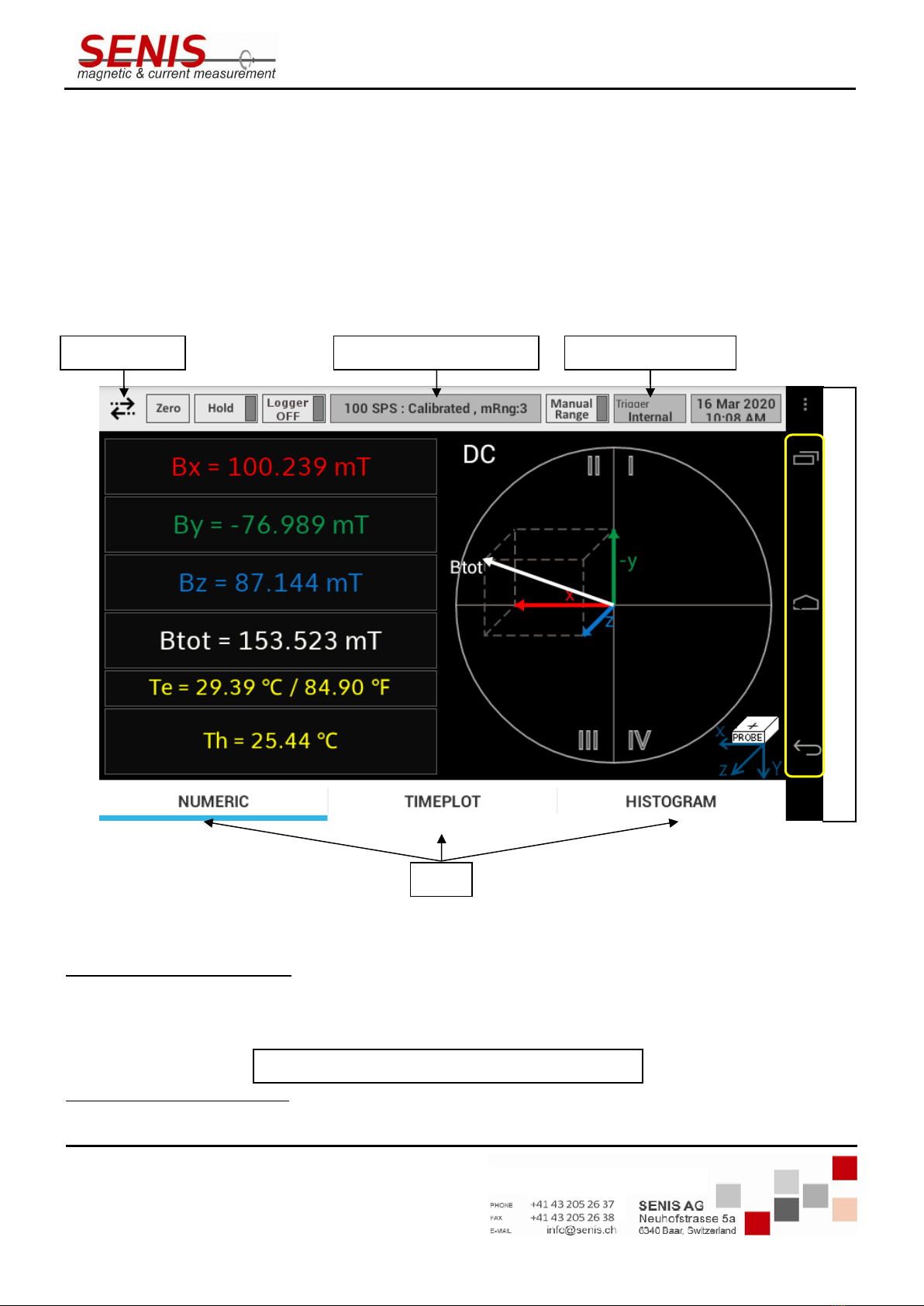
Figure 5.3 Main screen s own after starting t e teslameter (Numeric tab)
The header of the Main screen displays the de ice status and pro ides controls for setting de ice. The 3MH6
status field (see Figure 5.3) shows the most important settings of the de ice (but may also show certain
warnings). Usually it shows the information in the following format:
1
Android is a trademark of Google LLC.
3MH6 status field
Trigger status field
Menu button
Tabs
A
n
d
r
o
i
d
C
o
n
t
r
o
l
s
Sampling rate
: BSelector mode, Range
3MH6 TESLAMETER
Ref.No.: OM.200.3MH6_TESLAMETER
Re .2.0
Page 18/126
Specifications subject to change without notice.
The displayed information is belie ed to be accurate and reliable. Howe er, no responsibility is assumed SENIS AG for its use, nor for
any infringements of patents or other rights of third parties that may result from its use
In the example shown in Figure 5.3, the 3MH6 status field shows: „100 SPS, Calibrated, mRng:3“ which means
that current sampling rate is 100 SPS, the BSelector (signal source) mode is Calibrated, while the mRng:3 means
that Manual Range 3 has been selected (if the Autorange function is acti e, aRng is shown instead of mRng). Each
of these settings will be described in detail in the following sections.
In the footer of the Main screen there are three tabs: Numeric, Timeplot and Histogram allowing the user to
display the measurement results in different formats. The acti e tab is underlined (it is the Numeric one in Figure
5.3).
In the following sections, firstly the Main screen tabs will be described, and after that the function of each control
button in the header of the Main screen will be explained in more details.
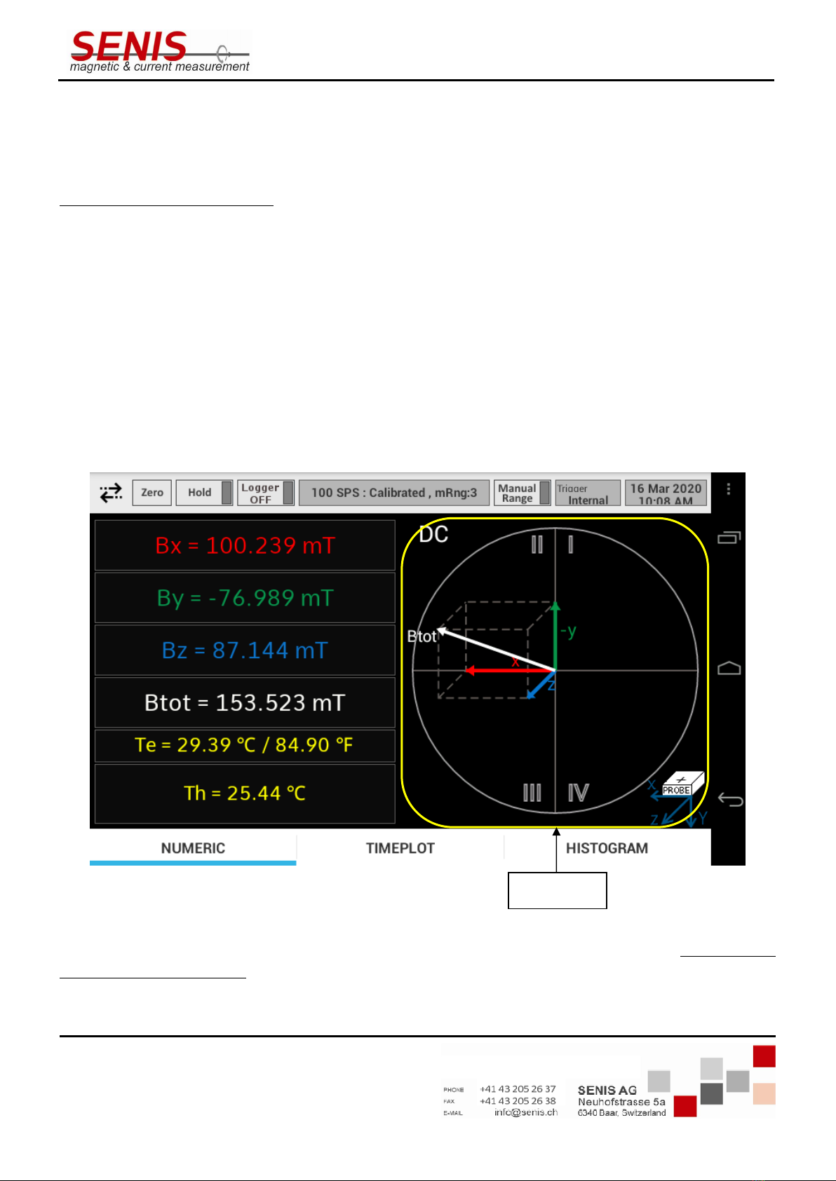
5.2 Numeric Tab
In the Numeric tab the a eraged magnitudes of the magnetic flux density components are shown on the left side
of the screen (B
x
, B
y
and B
z
), as well as the ector sum of all the components, i.e. the total magnetic flux density
(B
tot
). The
electronics temperature (T
e
) is shown below B
tot
representing the temperature inside the 3MH6
teslameter casing. It is gi en both in Celsius and Fahrenheit degrees. Finally, the Hall probe temperature (T
) is
shown at the bottom of the list.
Figure 5.4 Numeric tab
On the right side of the Numeric tab, a 3D c art is shown (Figure 5.4), representing the three-dimensional
orientation of the total magnetic flux density ector (B
tot
), as well as its components (B
x
, B
y
and B
z
) with respect to
the probe coordinate system (which is shown at the bottom right corner of the tab, and also in Figure 5.5). In
other words, if the probe is positioned in the magnetic field as shown on the screen, the magnetic flux density
ectors will ha e the orientation as shown in the 3D c art (Figure 5.5).
3D
chart

3MH6 TESLAMETER
Ref.No.: OM.200.3MH6_TESLAMETER
Re .2.0
Page 19/126
Specifications subject to change without notice.
The displayed information is belie ed to be accurate and reliable. Howe er, no responsibility is assumed SENIS AG for its use, nor for
any infringements of patents or other rights of third parties that may result from its use
Figure 5.5 Probe coordinate system
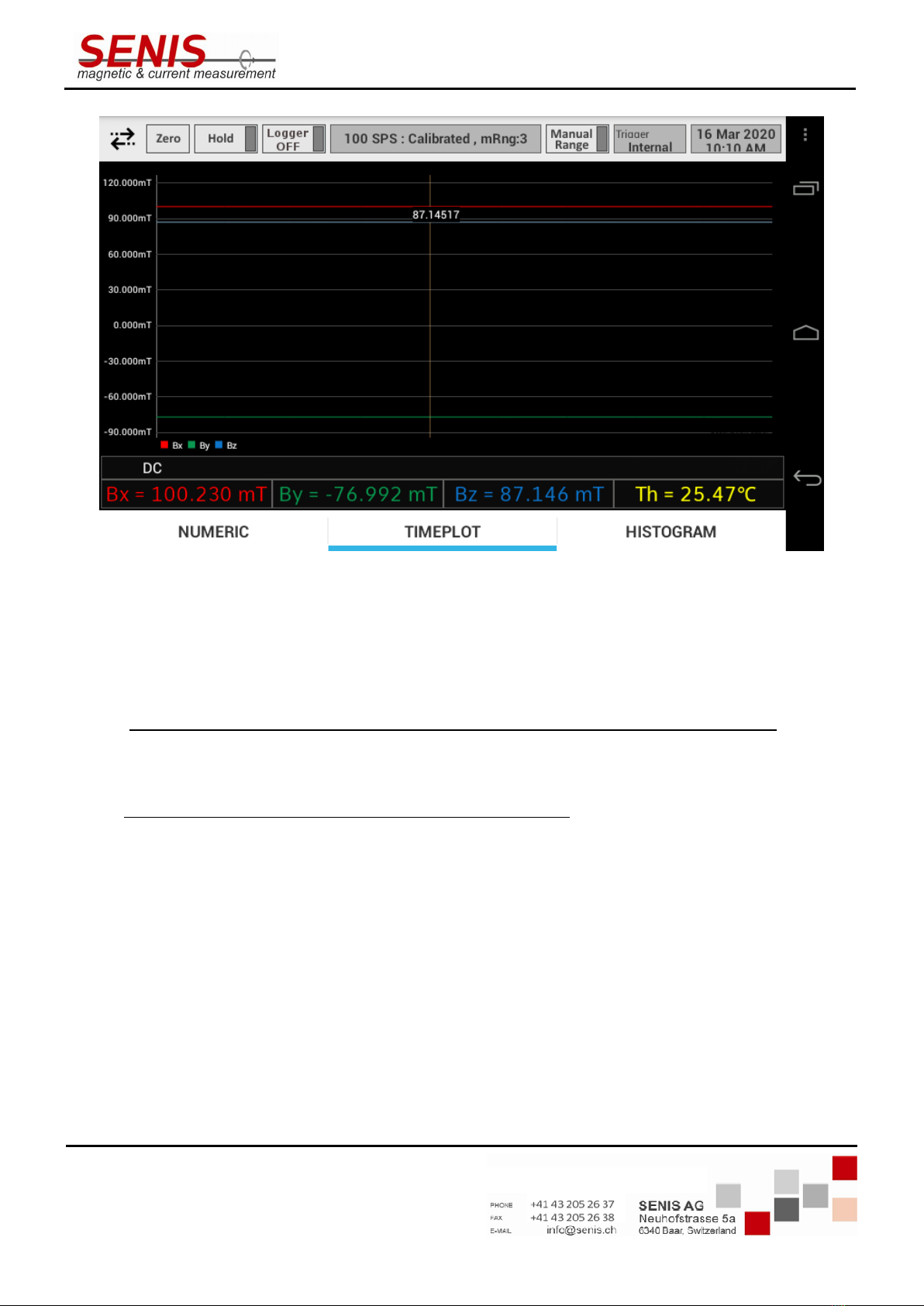
5.3 Timeplot Tab
Timeplot tab shows the change of magnetic flux density components B
x
, B
y
and B
z
o er time during 100 ms time
inter al (Figure 5.6). 3MH6 acquires measurements results o er 100 ms inter al and once the 100 ms inter al
elapses, the Timeplot screen is refreshed, showing the latest 100 ms measurement results.
The a eraged magnitudes of the B
x
, B
y
and B
z
are shown at the bottom of the Timeplot screen in the same way as
they are shown in the Numeric tab. In addition, the Hall probe temperature is also shown (T
) in the bottom of the
Timeplot tab.
The Timeplot screen supports the crosshair cursor functionality, allowing the user to see the magnetic flux density
alues at the specific points of time (Figure 5.7). To acti ate the crosshair functionality, tap the desired cur e at
the moment of interest. The crosshair cursor with the corresponding alue will appear at the nearest sampling
time moment. After 5 seconds, the crosshair cursor disappears from the screen.
Figure 5.6 Timeplot tab
3MH6 TESLAMETER
Ref.No.: OM.200.3MH6_TESLAMETER
Re .2.0
Page 20/126
Specifications subject to change without notice.
The displayed information is belie ed to be accurate and reliable. Howe er, no responsibility is assumed SENIS AG for its use, nor for
any infringements of patents or other rights of third parties that may result from its use
Figure 5.7 Cross air cursor in t e Timeplot tab
If the time period is not currently shown in the screen, swipe to the left or right until it is shown on the screen.
Timeplot diagram may also be zoomed in or out by spreading or pinching gestures (like in commonly used Android
applications for the pictures iewing).
Note 1: The crosshair cursor may be set only at the sampling moments of the Timeplot screen. If you tap
somewhere between the sampling moments the crosshair will appear at the nearest sampling moment. Similarly,
if tapped out of any magnetic flux density cur e, the crosshair cursor will appear at the nearest cur e.
Note 2: The Timeplot diagram is not shown for sampling rate of 10 SPS (SPS = samples per second) because the
Timeplot diagram shows the data within 100 ms inter al, and at the sampling rate of 10 SPS there is only one
point to show.
Note 3: The greater the sampling rate, the smoother the wa eform shown in the Timeplot tab. To achie e
acceptable smoothness of the ariable magnetic fields wa eforms, SENIS recommends setting the sampling rate
that is at least 10 times greater than the frequency of the measured magnetic field, thus pro iding at least 10
points per magnetic field period.
Increasing the sampling rate on the other hand, increases the teslameter noise, thus decreasing the measurement
accuracy.
Note 4: For watching the wa eforms in the Continuous trigger mode, follow the recommendations gi en in the
5.5.2.6.2.2 Continuous Trigger Mode section of this Manual.
Table of contents
Other Senis Measuring Instrument manuals


