Senix ToughSonic Series User manual

ToughSonic®
General Purpose Series
Ultrasonic Distance Sensors
PC Configurable and/or Push-Button Teachable
Installation and Operating Instructions for
ToughSonic 3 ToughSonic 12 ToughSonic 14
ToughSonic 30 ToughSonic 50
Senix Corporation
Aug 19, 2019 F 3.5.8 V46
©2015-2016 by Senix Corporation

®
Senix Corporation, 10516 Route 116 Suite 300, Hinesburg, VT 05461 USA
Web: www.senix.com, e-mail: Technical.Support@senix.com
Page 2 of 54 –Aug 19, 2019
ToughSonic® Family Sensors –Installation & Operating Instructions
Product
Declarations
Document Revisions
Initial Release 31 May 2015
General corrections 8 Apr 2016
General corrections 9 Nov 2016
New products added 19 Aug 2019
Related Products
SenixVIEW for Windows
A setup tool for ToughSonic series sensors, this
software installs on a PC and is used to configure
sensor options, select and calibrate outputs, view and
analyze measurements, and save the result to a PC hard
drive. Recalled configurations can restore or duplicate
an application without recalibration. View, chart, log,
and analyze sensor operation. Sensor firmware
upgrades can be done easily through SenixVIEW too.
Download SenixVIEW at no charge from:
https://senix.com/senixview-ultrasonic-sensor-software/
Setup Kits
Used for bench viewing or configuring sensors, kits
include power supply, terminal board and cables to
interconnect with your PC. A SenixVIEW thumb drive
with software, videos and manuals is also included (see
Software and Interconnection, page 15).
CE Compliance
ToughSonicfamily of ultrasonic sensors are
compliant with the CE Electromagnetic Compatibility
Directives and Standards listed below:
Directives: Electromagnetic Compatibility
(2004/108/EC)
Low-Voltage (2006/95/EC)
Standards: EMC: EN 61326-1:2006 Industrial
Safety: EN 61010-1:2001
Warranty
Senix makes no warranty, representation or guarantee
regarding the suitability of the products for any
particular purpose. All specifications are subject to
change without notice.
Senix, Inc. will repair or replace, at our option, any part
found by us to be defective in material or workmanship
if the product is received by Senix, freight prepaid,
within one year from the date of original shipment to
buyer.
Disclaimer and Release. The warranties, obligations
and liabilities of Senix and the remedies of buyer set
forth above are exclusive and in substitution for, and
buyer hereby waives, releases and renounces all other
warranties, obligations and liabilities of Senix and all
other rights, claim, and remedies of buyer against
Senix, expressed or implied, arising by law or
otherwise, including but not limited to: (A) Any
implied warranty or merchantability or fitness; (B) Any
implied warranty arising from course of performance,
course of dealing or usage of trade; (C) Any obligation,
liability, right, claim or remedy in tort, whether or not
arising from the negligence of Senix (whether active,
passive or imputed); and (D) Any obligation, liability,
right, claim or remedy for loss or damage to any
product.
Exclusion of Consequential and Other Damages. Senix
shall have no obligation or liability, whether arising in
contract (including warranty), tort (including active,
passive or imputed negligence) or otherwise, for loss of
use, revenue or profit with respect to any non-
conformance or defect in any product delivered under
this agreement, or for any other direct, incidental or
consequential damages.
Governing Law. The terms and conditions of this
agreement shall be governed by the domestic law of the
State of Vermont, U.S.A.
Repairs and Returns
Any returns must have a Return Material Authorization
(RMA) number.
Contact us at:
Mail: Senix Corporation
10516 Route 116 Suite 300
Hinesburg, VT 05461 USA
web: www.senix.com

®
Senix Corporation, 10516 Route 116 Suite 300, Hinesburg, VT 05461 USA
Web: www.senix.com, e-mail: Technical.Support@senix.com
Page 3 of 54 –Aug 19, 2019
ToughSonic® Family Sensors –Installation & Operating Instructions
Table of Contents
PRODUCT DECLARATIONS.......................2
Document Revisions_______________________2
Related Products__________________________2
CE Compliance___________________________2
Warranty ________________________________2
Repairs and Returns_______________________2
Table of Contents _________________________3
Terminology _____________________________4
ULTRASONICS OVERVIEW........................5
Introduction ______________________________5
Advantages______________________________5
Typical Applications _______________________5
SENSOR OVERVIEW...................................6
ToughSonic Product Features________________6
Startup Tips______________________________7
Specifications ____________________________8
Mechanical Details _______________________12
Mounting and Installation __________________12
Rear Features___________________________15
Target Indicator__________________________16
Output Status Indicators ___________________17
INTERFACES.............................................19
Wires Identification _______________________19
ToughSonic 3, 12, and 14 Output Selection ____20
Analog Outputs __________________________21
Serial Data Interface ______________________26
Serial Parameters ________________________27
Serial Data Protocols _____________________29
OPERATION ..............................................30
Power Up ______________________________30
Measurement Activation ___________________30
Synchronization__________________________32
Operating Range_________________________33
Measurement Process ____________________33
Sensor Viewing__________________________34
Measurement Rate _______________________36
Output Response Time ____________________36
Filters _________________________________37
Time Delays ____________________________40
Temperature Compensation ________________40
Precautions_____________________________40
SENIXVIEW SOFTWARE...........................41
Install SenixVIEW________________________ 41
Application Setups _______________________ 41
Connect a Sensor________________________ 42
Outputs & Indicators______________________ 43
Sensor Adjustment _______________________ 46
TEACH ADJUST ........................................47
Appendix A –List of Adjustable Features______ 49
LIST OF FIGURES
Figure 1 - Part Number Structure ..................................6
Figure 2 - Mechanical Drawing, ToughSonic 3, 12, 14
metric thread...............................................................12
Figure 3 - Mechanical Drawing, ToughSonic 30, 50, and
50P ..............................................................................12
Figure 4 - Sensor Orientation ......................................12
Figure 5 - Mounting.....................................................13
Figure 6 - Sensor Rear Features...................................15
Figure 7 - Target Indicator Functions ..........................16
Figure 8 - Output Status Indicator Operations ............18
Figure 9 - RS-232 PC COM Port Connections ...............20
Figure 10 - Voltage Output Wiring ..............................21
Figure 11 - Sourcing Current Loop Wiring ...................21
Figure 12 - Sinking Current Loop Wiring......................21
Figure 13 - SenixVIEW Analog Adjustments ................23
Figure 14 - Sinking Switch Output Wiring....................23
Figure 15 - Sourcing Switch Output Wiring .................24
Figure 16 - Switch Hysteresis & Window Modes .........25
Figure 17 - SenixVIEW Switch Adjustment ..................25
Figure 18 - RS-232 PC COM Port Connections .............26
Figure 19 - RS-232 Connections...................................26
Figure 20 - Serial-485 Connections..............................27
Figure 21 - RS-485 Network Wiring.............................27
Figure 22 - Measurement Activation Selections..........31
Figure 23 - SenixVIEW Polling Controls .......................31
Figure 24 - SYNC Wiring ..............................................32
Figure 25 - SYNC Phases and Timing ...........................32
Figure 26 - Measurement Process Diagram ................33
Figure 27 - SenixVIEW Distance Displays.....................34
Figure 28 - Filters Block Diagram ................................38
LIST OF TABLES
Table 1 - Wire Assignments ____________________ 19
Table 2 - Measurement Activation Summary ______ 30
Table 3 - Maximum Range vs. Measure Rate ______ 36
Table 4 - Filter Response Time __________________ 39
Table 5 - Pushbutton TEACH Features List_________ 49

®
Senix Corporation, 10516 Route 116 Suite 300, Hinesburg, VT 05461 USA
Web: www.senix.com, e-mail: Technical.Support@senix.com
Page 4 of 54 –Aug 19, 2019
ToughSonic® Family Sensors –Installation & Operating Instructions
Terminology
Terms listed here are shown in italics throughout this
document. An asterisk (*) indicates a SenixVIEW
configurable parameter.
Analog An electrical output type that varies in proportion to
measured distance. Analog output types can be either
current loop or voltage.
Analog High Value* The maximum (highest) value of an
analog output. For example, the Analog High Value for
a 4-20 mA current loop analog output is 20 mA.
Computer configurable models allow this value to be
user-entered.
Analog Low Value* The minimum (lowest) value of an
analog output. For example, the Analog Low Limit value
for a 0-10 VDC voltage output is 0 volts. Computer
configurable models allow this value to be user-entered.
Analog Window* A range of distances between two
endpoints, within which the analog output will vary
between the analog low value and analog high value
proportional to measured distance.
Current Loop Output* An analog output type that drives
an electrical current proportional to measured distance.
ToughSonic sensors provide 4-20 mA or SenixVIEW
customized output ranges in sourcing or sinking current..
Deadband The small distance near the sensor face within
which distance cannot be measured. See also Range
MIN.
Endpoint* One of two end distances representing the outer
limits of the analog window.
Hysteresis* The distance between a switch’s Setpoint and
OFF Distance. It reverses direction about the Setpoint if
the Polarity is reversed.
Ingress Rating An enclosure rating that identifies how
susceptible a product is to the entry (ingress) of external
objects or liquids.
Measurement Rate* The repetitive rate that the sensor
measures distance (see response time).
Measurement Interval* The time between measurements
[1 / Measurement Rate].
Measurement Process* The measurement, filtering and
time delays that affect sensor outputs (p 33).
Maximum Range The maximum target detection distance
of a sensor model; may be overridden by Range MAX (p
33).
Near MIN A distance extending 0.25 in. farther than Range
MIN within which the Target Indicator will flash as a
warning.
Operating Range* The range of distances between the
range MIN and range MAX values (p 33).
Optimum Range The range of target distances
recommended for optimum performance in varying
environmental conditions.
Output Status Indicator An indicator at the rear of
ToughSonic 3,12, and 14 that shows the status of an
analog, switch or serial data output. There is a separate
output status indicator for output #1 (black wire) and
output #2 (white wire).
Polarity* The behavior of a switch output at it’s setpoint,
defined as “on-closer” or “on farther”. A switch turns
OFF in the reverse direction after the Hysteresis
distance.
Range MAX* The farthest distance of the Operating Range;
user adjustable in SenixVIEW.
Range MIN* The nearest distance of the Operating Range;
a target is not detected closer than the greater of Range
MIN or the Deadband.
RS-232* An electrical interface standard used to transfer
information using serial data communications. This is a
single ended interface with a specified maximum range
of 50 feet (15 meters) that typically supports one device.
RS-485* An electrical interface standard used to transfer
information using serial data communications. This is a
long distance differential interface capable of supporting
multiple addressable devices.
Response Time* The time required for sensor outputs to
respond to measurements; affected by measurement rate
and filter selections.
Serial Data Distance data output over the serial interface as
opposed to the analog or switch lines
Setpoint* The distance a switch output turns ON. (see also
OFF distance, polarity and Hysteresis)
Sinking Switch* A switch where current flows into the
sensor to ground from an externally sourced load when
turned ON (output voltage low when ON).
SenixVIEW Senix PC–based software used to configure and
install ToughSonic sensors.
Sourcing Switch* A switch where current flows from the
sensor (sensor power input is the source) to the load
when turned ON (output voltage high when ON).
Switch* An electrical output type that is either ON or OFF.
ToughSonic® switches are solid state and can be either
sinking or sourcing type.
SYNC* A wired configuration that synchronizes the timing
of two or more sensors to prevent crosstalk or ensure
simultaneous measurements.
SYNC Interval The time interval of measurement of all
SYNC sensors. It equals the number of SYNC phases x
measurement interval.
Target Any object or material that reflects ultrasonic energy
back to the sensor thus allowing the sensor to measure its
distance.
Target Indicator A rear indicator that shows the status of a
detected target and more.
Teach* A Senix product feature that uses a pushbutton to to
store a current target distance measurement into memory
and automatically calibrate the output(s).
Time Delay* A time period triggered by a set of conditions
and, after those conditions persist for the entire period,
cause a secondary event to occur. There are several user-
selected time delay features available.
Ultrasonic A sound wave of a frequency greater than
20,000 Hz, typically above the range of human hearing.
Voltage Output* An analog output type that drives an
electrical voltage proportional to measured distance.
ToughSonic sensors provide industry standard or
SenixVIEW customized output ranges.
®
Senix Corporation, 10516 Route 116 Suite 300, Hinesburg, VT 05461 USA
Web: www.senix.com, e-mail: Technical.Support@senix.com
Page 5 of 54 –Aug 19, 2019
ToughSonic® Family Sensors –Installation & Operating Instructions
Ultrasonics
Overview
Introduction
Senix sensors measure the distance or presence of a
target object by sending a sound wave, above the range
of hearing, at the object and then measuring the time for
the sound echo to return. Knowing the speed of sound,
the sensor can determine the distance of the object from
the transducer element.
Advantages
•Non-contact
Measures through the air without touching the
target object, at relatively large distances.
•Object Ranging
Object distance is measured rather than just the
presence or proximity.
•Distance Proportional Output
The sensor’s outputs are proportional or affected
by the measured target distance.
•High Resolution
Precise discrimination of target position.
•Unaffected by Target’s Optical
Characteristics
The sensor’s operation is not sensitive to ambient
light levels, the color of the target, or target is
optically transparency/reflectivity.
•Sensitive
Detects large and small objects (smaller objects
must be closer)
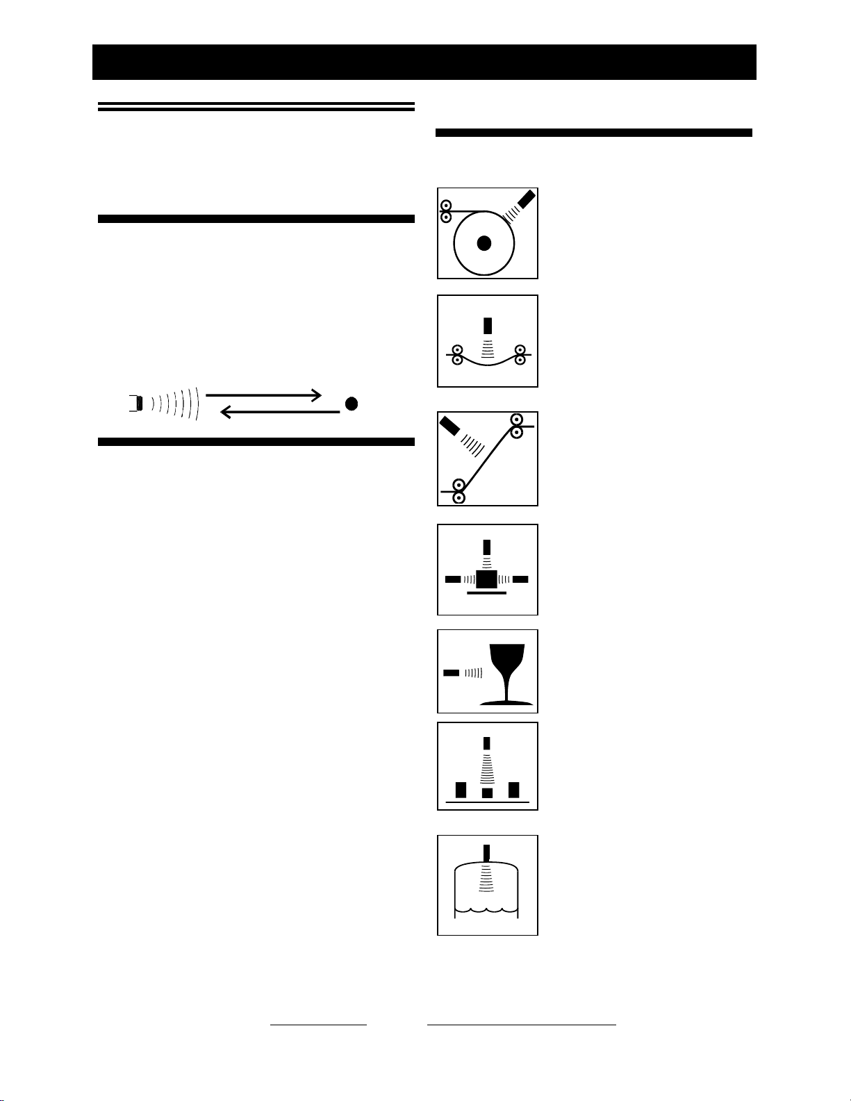
Typical Applications
Roll Diameter
Measure the size of a roll to
control tension or speed, or
determine when full or empty.
Loop Control
Precisely control the position of
material loops, including wires,
tubes and webs.
Web Break
Rapidly detect a broken web in a
printing press or paper machine.
Dimensioning
Determine the size of an object for
information or to determine its
volume or width.
Proximity
Determine the presence of objects
to count or control their movement.
Sort/Select
Sort or select objects based on
differences in their physical
dimensions.
Level Measurement
Measure or control the level of
liquid or solid materials in tanks or
bins for inventory or
batching….and many more...
M
o
d
e
l
U
L
T
R
A
-
S
(
2
)
U
l
t
r
a
s
o
n
i
c
e
c
h
o
r
e
t
u
r
n
s
f
r
o
m
t
a
r
g
e
t
(
1
)
U
l
t
r
a
s
o
n
i
c
p
u
l
s
e
t
r
a
n
s
m
i
t
t
e
d
f
r
o
m
s
e
n
s
o
r
®
Senix Corporation, 10516 Route 116 Suite 300, Hinesburg, VT 05461 USA
Web: www.senix.com, e-mail: Technical.Support@senix.com
Page 6 of 54 –Aug 19, 2019
ToughSonic® Family Sensors –Installation & Operating Instructions
Sensor
Overview
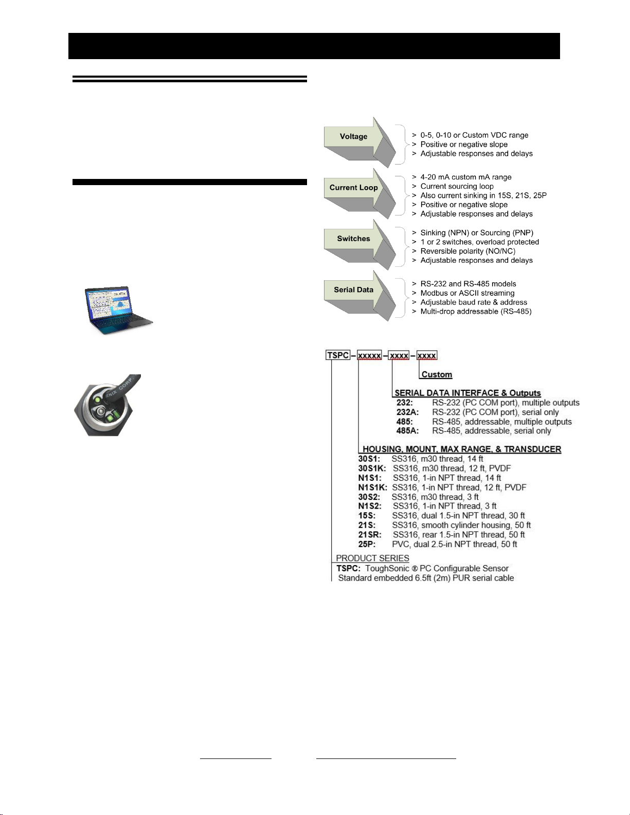
ToughSonic Product
Features
ToughSonicsensors measure distance without contact
and are designed for tough industrial environments.
Rapid PC Setup & Control
PC setup gives you control over
all sensor outputs and features.
View, analyze and save sensor
setups for rapid implementation
or cloning.
Pushbutton “Teachable”
Some models utilize a rear TEACH
button to make many common
adjustments. See the Teach Adjust
section. Rear indicators provide
target and output status. The TEACH
button can be disabled for security
using SenixVIEW. The TEACH button is unavailable
on the ToughSonic 50 and 50RM models and serial-
only models.
Packaging
ToughSonic models are housed in rugged 316 stainless
steel or durable PVC, with permanently attached
interface cables. Sensors are potted and sealed to
operate in wide humidity and temperature ranges.
Industry Standard Interfaces
Multiple simultaneous outputs, each with many
SenixVIEW adjustable features.
Part Numbers
Figure 1 - Part Number Structure
Identification
The ToughSonicmodel number and serial number are
printed on the label on the side of the housing.

®
Senix Corporation, 10516 Route 116 Suite 300, Hinesburg, VT 05461 USA
Web: www.senix.com, e-mail: Technical.Support@senix.com
Page 7 of 54 –Aug 19, 2019
ToughSonic® Family Sensors –Installation & Operating Instructions
Startup Tips
New or first-time users can use this condensed guide
for assembly, connection to a PC, and basic sensor
changes from default values before installation.
The sensor communicates with a Windows PC through
the serial port or USB port. A UAN-Kit from Senix is
recommended for connecting to your PC. It includes
software, a termination board, and cables (see page
Error! Bookmark not defined.).
▪Install the Software
Put the SenixVIEW thumb drive into your PC. Open
the contents and run SenixVIEW Version 3.4.xxx
Setup.exe to install. Start SenixVIEW.
▪Connect the Components
The sensor uses colored wires for power,
communication, and outputs. For a basic terminal board
connection, we’ll use 4 of the sensor’s wires:
a. Brown for DC power (DC+)
b. Blue for ground (GND and digital reference)
c. Gray and Yellow for digital communication.
Connect them to the labeled Senix terminal board.
Protect all bare wires from contacting one another
whether connected or not. Ensure the terminal grips the
stripped wire, not its colored jacket.
Plug the data communication cable into the terminal
board RJ jack and your serial port (-232 models), or
into the USB adapter (optional for -232 and required for
-485 models). (For USB adapters see page 15)
Put the DC power supply cable into the jack on the
terminal board, and the supply into an AC source. All
sensors will faintly tick when powered.
▪Connect to Your Sensor (using serial port)
Start SenixVIEW.
Menu bar: Sensor >Connect for a dialog box. All new
sensors have network address 1. Use Baud rate 9600.
The serial port is generally identified COM 1. Click
Connect.
▪OR Connect to Your Sensor (using a USB port)
Start SenixVIEW.
Menu bar: Sensor >Connect for a dialog box. All new
sensors have network address 1. Use Baud rate 9600.
Select the COM port from the choices or run Com Port
Survey. If COM port is higher than the 12 shown. Edit
>User Preferences…> Connection/ Starting COM port:
and enter new start number. Return to Connect Sensor
and repeat connection with any available green ports.
For more detail, see “Connect a Sensor”, page 42.
▪SenixVIEW Quick Tour
Once a sensor is connected, it can be viewed in the
SENSOR view. Any changes are done in the
WORKSPACE view and transferred to the sensor.
Basic layout of the main screen:
a. Range and basic setup values, all editable.
b. Workspace and Sensor views
c. File saving and retrieval button
d. Dialog screens for additional setup
e. Analysis tools
f. Output setup and simulated meters (editable)
Setup Basics (advanced description starts page 21)
When sensor is found, answer YES to copy sensor
setup to the Workspace. You are left in Sensor View
showing the sensor reading and its current setup.
To make changes, click the WORKSPACE button.
-To change a Range, Endpoint, or output value, just
click on the value and enter a new one.
-To reverse the analog slope, right-click the High- or
Low-value endpoint.
-To assign outputs, click WIRING and assign black and
white wires as needed. Any changes in Workspace
make it different than the Sensor, shown by the unequal
symbol. Transfer WORKSPACE to SENSOR.
▪Save the Setup to the Sensor
To move changes to sensor, right click and drag
WORKSPACE to SENSOR. Any changes not sent to
the sensor will be lost when closing SenixVIEW.
▪Save the Setup to the PC.
Right click WORKSPACE and drag it to FILE.
▪Mounting Tips
Sensor must be mounted perpendicular to the object to
be measured for sound echoes to return. The sensor
cannot sense in a space less than the default Minimum
Range value. The sensor will ignore targets or surfaces
beyond the Max Range value. Avoid echoes from pipe
fittings, welds, and fixed objects with careful
placement. The sensor will return a distance value from
the first surface found within range. Contact Senix
technical support for setup assistance.
®
Senix Corporation, 10516 Route 116 Suite 300, Hinesburg, VT 05461 USA
Web: www.senix.com, e-mail: Technical.Support@senix.com
Page 8 of 54 –Aug 19, 2019
ToughSonic® Family Sensors –Installation & Operating Instructions
Specifications
A summary of sensor specifications and features is
shown in the following table.
Model (FW 3.5.8)
ToughSonic 3
ToughSonic 12
ToughSonic 14
Photo
Maximum Range
Deadband (minimum)
3 ft (91cm)
1.75 in (4.4 cm)
12 ft. (3.7 m)
3 in. (76 mm)
14 ft. (4.3 m)
4 in. (10.2 cm)
Optimum Range
(small targets, dry
materials, hot)
24 in (61cm)
8 ft (2.4m)
10 ft (3m)
Outputs, full-featured
models:
Outputs, Serial-only:
NONE
Two outputs: SenixVIEW selectable as 0-10 VDC (or custom), 4-20 mA (or custom)
sourcing, PNP or NPN switches
Switches: 150 mA, SenixVIEW configured as PNP (@ input voltage) or NPN (external
40 VDC max.), setpoint mode or window mode
Voltage:0-10 or SenixVIEW configured, 10 mA max (min 15 VDC input for full 10
VDC output)
Current Loop:4-20 mA or SenixVIEW configured, 450max @ >15VDC, 250max
@ 10 VDC
Indicators
Round LED: Power/Target. Square & Rectangular LEDs: Data, switch or analog
status (configurable)
Serial-only models: Round LED Power/Target
Serial interface,
Interface protocol
Modbus slave, ASCII, or SYNCH. RS-232 or RS-485 interface, depends on model. RS-
485 models are 2-wire multi-drop addressable (addresses 1-247). Baud rates 9600 -
115200, none or even parity, 8 bits, one stop bit. SenixVIEW configured.
Power Input
10-30 VDC @ 55 mA max
DC Current @
typical 24VDC input
+I/O
Typical 45 mA @ 24VDC input +I/O
DC Current, Serial-
only
Typical 30 mA @ 24VDC
Typical 35 mA @ 24VDC
Typical 35 mA @ 24VDC
Environmental
Ingress: IP-68, NEMA-4X Humidity: 0-100% (avoid heavy condensation) Temp: -40 to
+158 F (-40 to +70 C)
Transducer,
Beamwidth
Rugged piezoelectric,
nominal beam width ~12
degrees @ -3 dB, approx.
conical shaped pattern
PVDF piezoelectric,
nominal beam width ~12
degrees @ -3 dB, approx.
conical shaped pattern
Rugged piezoelectric,
nominal beam width ~12
degrees @ -3 dB, approx.
conical shaped pattern

®
Senix Corporation, 10516 Route 116 Suite 300, Hinesburg, VT 05461 USA
Web: www.senix.com, e-mail: Technical.Support@senix.com
Page 9 of 54 –Aug 19, 2019
ToughSonic® Family Sensors –Installation & Operating Instructions
Model (FW 3.5.8)
ToughSonic 3
ToughSonic 12
ToughSonic 14
Transducer frequency
240 kHz
120 kHz
120 kHz
Measurement rate
Default: 50 msec (20 Hz)
Adjustable from 5 msec to 2.8 hours; faster rates limit max target distance
Performance
Repeatability: Greater of +/-0.03 in. (0.76 mm) or 0.2% of target distance in stable
environment
Accuracy: Better than 0.5% of target distance in stable, homogeneous air environment;
affected by temperature gradients, target echo strength, speed of sound in air or vapors.
Resolution (analog)
4100 steps over 0-10 VDC and 3279 steps over 0-20 mA (scaled between user-set
distance endpoints)
Resolution (serial
data)
0.0034 in. (0.086 mm)
Adjustments
Pushbutton Teach (except in serial-only version) or SenixVIEW software (included)
Cable, full outputs
(embedded)
6.5-ft (2m) 6-wire with shield, tinned ends, PUR
Cable, serial-only
6.5-ft (2m) 4-wire with shield, tinned ends, PUR
Max serial cable
length
RS-232: 50ft (15 m), RS-485: 3937ft (1200m).
Weight
10.3 oz. (0.29 kg)
10.4 oz (0.29 kg)
10.4 oz (0.29 kg)
Housing material,
Mount
316 Stainless, M30x1.5 mm thread OR 316 Stainless, 1-in NPT thread
Dimensions
(Dia x Length)
1.2 in. (30.4mm) x 4.064 in. (103mm)
Default: RangeMIN
RangeMAX
Switch #1 Setpoint
Switch #2 Setpoint
Analog Low Endpoint
Analog High Endpoint
1.75 in. (4.4 cm)
36 in. (91 cm)
12 in. (30.5 cm)
18 in. (46 cm)
1.75 in. (4.4 cm)
24 in. (61 cm)
3 in. (76 mm)
144 in. (3.7 m)
12 in. (30.5 cm)
18 in. (46 cm)
96 in. (244 cm)
3 in. (7.6 cm)
4 in. (10.2 cm)
168 in. (427 cm)
12 in. (30.5 cm)
24 in. (61 cm)
4 in. (10.2 cm)
120 in. (305 cm)
Options Interface:
Mount method:
Outputs:
RS-232 or RS-485
M30 or 1-in NPT thread
Two outputs or serial only
Ordering
Refer to Part Numbers and Figure 1, “Part Number Structure”, pg 6

®
Senix Corporation, 10516 Route 116 Suite 300, Hinesburg, VT 05461 USA
Web: www.senix.com, e-mail: Technical.Support@senix.com
Page 10 of 54 –Aug 19, 2019
ToughSonic® Family Sensors –Installation & Operating Instructions
Model (FW 3.5.8)
ToughSonic 30
ToughSonic 50 &
ToughSonic 50RM
(Rear mounted)
ToughSonic 50P
Photo
Maximum Range
Deadband (minimum)
30 ft (9.1 m)
10 in (25.4 cm)
50 ft (15.2 m)
12 in (30.5 cm)
Optimum Range (small
targets, dry materials, hot)
20 ft (6.1 m)
33 ft (10.1 m)
Outputs, full-featured
models:
Outputs, Serial-only:
NONE
Five Outputs: 0-10 VDC, 4-20 mA sourcing, 4-20 mA sinking, two switches
Switches: 150 mA, SenixVIEW configured as PNP (@ input voltage) or NPN (external
40 VDC max.)
Voltage:0-10 or SenixVIEW configured, 10 mA max (min 15 VDC input for full 10
VDC output)
Current Loop:4-20 mA or SenixVIEW configured, 450max @ >15VDC, 250max
@ 10 VDC
Indicators
Round LED: Power/Target. Square & Rectangular LEDs:Data, switch or analog
status (configurable) 50RM and 50RM Serial only: None
Serial-only models: Round LED Power/Target (except 50RM)
Serial interface,
Interface protocol
Modbus slave, ASCII, or SYNCH. RS-232 or RS-485 interface, depends on model.
RS-485 models are 2-wire multi-drop addressable (addresses 1-247). Baud rates 9600 -
115200, none or even parity, 8 bits, one stop bit. SenixVIEW configured.
Power Input
10-30 VDC @ 70 mA max
DC Current @
typical 24VDC input +I/O
Typical 45 mA @ 24VDC input +I/O
DC Current, Serial-only
55 mA max, Typical 35 mA @ 24VDC
Environmental
Ingress: IP-68, NEMA-4X Humidity: 0-100% (avoid heavy condensation)
Temp: -40 to +158 F (-40 to +70 C)
Transducer,
Beamwidth
Rugged piezoelectric, nominal beam width ~12 degrees @ -3 dB, approx. conical
shaped pattern
Transducer frequency
75 kHz
50 kHz
50 kHz
Measurement rate
Default: 10 msec (10 Hz)
Default: 20 msec (5 Hz)
Adjustable from 5 msec to 2.8 hours; affected by filter selections; faster rates limit max
target distance

®
Senix Corporation, 10516 Route 116 Suite 300, Hinesburg, VT 05461 USA
Web: www.senix.com, e-mail: Technical.Support@senix.com
Page 11 of 54 –Aug 19, 2019
ToughSonic® Family Sensors –Installation & Operating Instructions
Model (FW 3.5.8)
ToughSonic 30
ToughSonic 50
ToughSonic 50P
Performance
Repeatability: 0.2% of target distance in stable environment
Accuracy: Better than 0.5% of target distance in stable, homogeneous air
environment; affected by temperature gradients, target echo strength, speed of sound in
air or vapors.
Resolution (analog)
4100 steps over 0-10 VDC and 3279 steps over 0-20 mA (scaled between user-set
distance endpoints)
Resolution (serial data)
0.0068 in. (0.172 mm)
0.0135 in. (0.343mm)
Adjustments
Pushbutton Teach (except
on serial-only models) or
SenixVIEW software
(included)
SenixVIEW software (included)
Cable, full outputs
(embedded)
6.5-ft (2m) 9-wire with shield, tinned ends, PUR
Cable, serial-only
embedded
6.5-ft (2m) 4-wire with shield, tinned ends, PUR
Max serial cable length
RS-232: 50ft (15 m), RS-485: 3937ft (1200m).
Weight
22.6 oz. (0.64 kg)
29.9 oz (0.82 kg)
29.1 oz (0.82 kg)
Housing material,
Mount
316 Stainless,
Dual 1.5 in NPT
316 Stainless cylinder,
Clamp to mount 50RM:
rear 1.5 in NPT
PVC,
Dual 2.5 in NPT
Dimensions
(Dia x Length)
1.2 in. (30.4mm) x 4.064
in. (103mm)
50: 2.3 in (59mm) x 4.8
in (122 mm)
2.5 in (63.5 mm) x 5.0 in
(127 mm)
50RM: 2.5 in (63 mm) x
5.9 in (150mm)
Default: RangeMIN
RangeMAX
Switch #1 Setpoint
Switch #2 Setpoint
Analog Low Endpoint
Analog High Endpoint
10 in. (25.4 cm)
30 ft. (9.1 m)
36 in. (91.4 cm)
48 in. (121.9 cm)
10 in. (25.4 cm)
240 in. (609 cm)
12 in. (30.5 cm)
50 ft. (15.2 m)
36 in. (91.4 cm)
48 in. (121.9 cm)
12 in. (30.5 cm)
400 in. (1016 cm)
12 in. (30.5 cm)
50 ft. (15.2 m)
400 in. (1016 cm)
18 in. (45.7 cm)
400 in. (1016 cm)
12 in. (30.5 m)
Options Interface:
Mount method:
Outputs:
RS-232 or RS-485
1.5 in NPT both ends
Clamp. ( 50RM: rear
thread 1.5-in NPT)
2.5 in NPT either end
Five outputs or serial only
Ordering
Refer to Part Numbers and Figure 1, “Part Number Structure”, pg 6
®
Senix Corporation, 10516 Route 116 Suite 300, Hinesburg, VT 05461 USA
Web: www.senix.com, e-mail: Technical.Support@senix.com
Page 12 of 54 –Aug 19, 2019
ToughSonic® Family Sensors –Installation & Operating Instructions
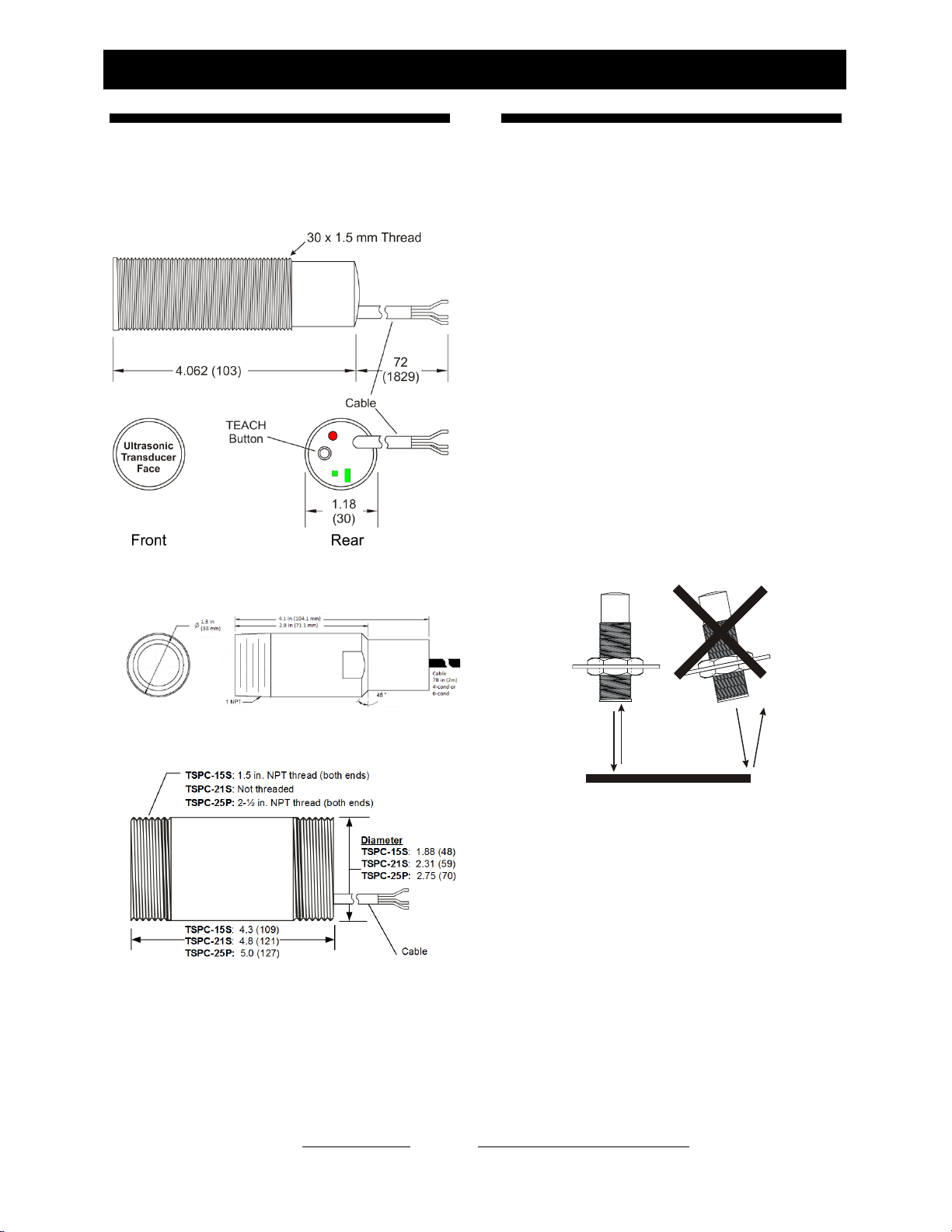
Mechanical Details
Dimensions are inches (mm). Distance is measured
between the ultrasonic transducer face (the end
opposite the cable) and the target.
Figure 2 - Mechanical Drawing, ToughSonic 3, 12, 14
metric thread
Mechanical Drawing, ToughSonic 3, 12, & 14 NPT thread
Figure 3 - Mechanical Drawing, ToughSonic 30, 50, and
50P
Mounting and
Installation
Precautions
Only hand tighten the sensor and never apply a
wrench to the body. When tank mounting to a domed
or round tank, mount the sensor perpendicular with
the target surface. Mount the sensor directly to the
tank ceiling at a flanged opening. If a riser is added, it
must be smooth-walled and a minimum 3-in
diameter. The sensor beam width is nominally 12-14
degrees at the -3dB boundary, however surfaces
outside that can return echoes as well. Round off the
lower ID of the riser to prevent detection. Provide
shade for outside installations to prevent erroneous
measurements due to artificial heating of the sensor
when temperature compensation is active. Mount the
sensor away from the inner walls of tanks. Seams and
fixtures can interfere with measurements.
Orientation
Orient the sensor perpendicular to the target object
for best results as shown in Figure 4.
Figure 4 - Sensor Orientation
Ultrasound energy must return to the sensor or the
sensor will not detect a target. Curved or spherical
objects generally reflect a portion of the energy back
to the sensor but with lower reflected energy. A flat
surface, however, is detectable at a greater distance.
Foreground interfering objects can be ignored by
setting the Range MIN value in SenixVIEW.
Maintenance & Cleaning
Dust accumulation on the sensor face can be cleaned
by blowing pressurized air across the sensor face.
Dust does not affect performance unless it builds on
the transducer. Positioning the sensor facing
downward rather than upward will minimize material
accumulation in some applications. The sensor face
DIRECTION
OF MEASUREMENT

®
Senix Corporation, 10516 Route 116 Suite 300, Hinesburg, VT 05461 USA
Web: www.senix.com, e-mail: Technical.Support@senix.com
Page 13 of 54 –Aug 19, 2019
ToughSonic® Family Sensors –Installation & Operating Instructions
can be cleaned with isopropyl alcohol or window
cleaner. DO NOT use solvents such as MEK or
acetone on ToughSonic sensors.
Metric ToughSonic 3, 12, and 14
These sensors are shipped with two 30mm stainless
nuts. The sensor mounts through a 1.18-in (31mm)
hole in a mounting plate as shown in Figure 5. This
hole may be a component of the user equipment or a
Senix bracket and must be rigid for best performance.
Position the sensor in the hole and fasten it to the
plate with the two nuts provided. The sensor position
can be altered a couple of inches depending on the
nut positions. If accurate close-range distance is
important, position the sensor so the closest target is
always beyond the deadband (also see Range MIN on
page 33).
Figure 5 - Mounting
NPT ToughSonic 3, 12, and 14
These sensors have 1-in NPT male threads at the
front end to install in a 1-in NPT threaded hole or
flange. The sensor can also be held by clamp.
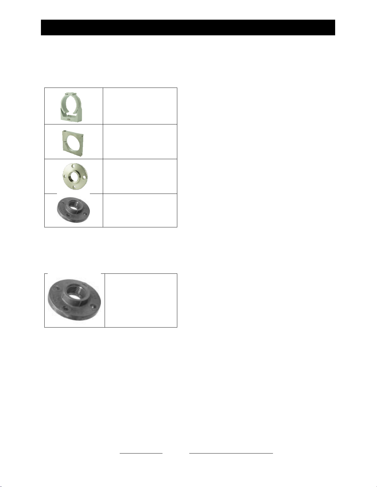
Mounting Hardware
Metric ToughSonic 3, 12, and 14 series
UA-MB30-SS
Stainless steel, flat bracket, non-
adjustable angle
UA-MB30-SS90
Stainless steel, 90-degree mounting,
non-adjustable angle
UA-MB30-NYBM
Nylon, clamps to sensor, non-
adjustable angle.
UA-MB30-NYSW
Nylon adjustable angle bracket with
internal 30mm thread. Adjust sensor
angle, then tighten to lock sensor in
position
UA-SWD-30-2NPT
Delrin adapter allows 30mm threaded
sensor to mate with
2-in. NPT flange or nipple. Elevates 2-
in for use with 2-in flange.
UA-SWED-30-2NPT
Delrin adapter allows 30mm threaded
sensor to mate with
2-in. NPT flange or nipple. Elevates 4-
in for use with 2-in flange.
UA-NUT30-SS
One pair (SS316).stainless steel
m30x1.5 nuts
(Included with new sensor)
ToughSonic 30 Series
The ToughSonic 30 threads into a 1.5-in NPT flange
or pipe thread.
UA-CLIC-15
PVC bracket
Optional for ToughSonic 30
UA-FM-15
Gray PVC flange for 1.5-in NPT
®
Senix Corporation, 10516 Route 116 Suite 300, Hinesburg, VT 05461 USA
Web: www.senix.com, e-mail: Technical.Support@senix.com
Page 14 of 54 –Aug 19, 2019
ToughSonic® Family Sensors –Installation & Operating Instructions
ToughSonic 50 Series
ToughSonic 50 series includes stainless steel and
PVC housings.
UA-CLIC-21
PVC bracket
Included with ToughSonic 50
UA-MB-SS
Stainless steel clamp bracket
bolts to surface in fixed
position
Optional for ToughSonic 50
UA-FM-SS15
Stainless steel flange. Fits rear
mount ToughSonic 50RM
UA-FM-15
Gray PVC flange. Fits rear
mount ToughSonic 50RM
ToughSonic 50P Series
ToughSonic 50P model threads into a 2.5-in NPT
flange or pipe nipple. Observe precautions (page 12).
UA-FM-20
Gray PVC flange with 2-in
NPT thread. Fits ToughSonic
50P
®
Senix Corporation, 10516 Route 116 Suite 300, Hinesburg, VT 05461 USA
Web: www.senix.com, e-mail: Technical.Support@senix.com
Page 15 of 54 –Aug 19, 2019
ToughSonic® Family Sensors –Installation & Operating Instructions
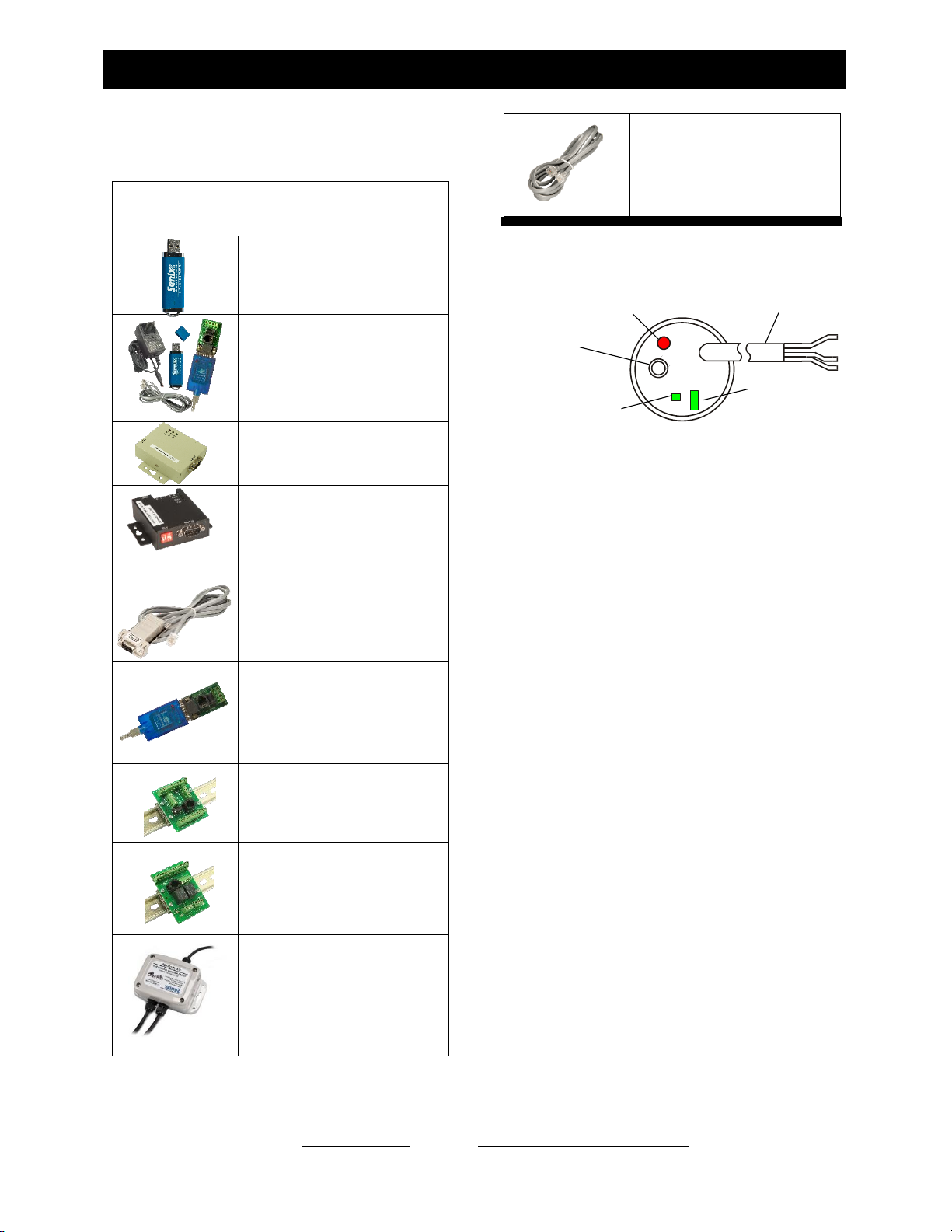
Software and Interconnection
The following accessories are available.
Configuration and Communication
SenixVIEW Software
Configure, test and clone sensors.
Compatible with all ToughSonic
models. Download free from
www.senix.com
UAN-KIT-USB-232
UAN-KIT-USB-485
PC Interface kits. Choose RS-232
or RS-485 to match sensor.
Converter, terminal block, power
supply, data cable, thumb drive
included.
UA-USB-232-ISO
Use with UA-CC-232 to connect to
a USB port at the PC with Isolated
inputs. 3 ft USB cable
UA-USB-485-ISO
Use with UA-CC-485 to connect to
a USB port at the PC with Isolated
inputs.
UA-CC-232
UA-CC-485
DB9 adapter and 6-ft data cable.
Joins ISO converter to termination
boards.
UA-USB-232-TB
UA-USB-485-TB
Non-isolated serial converter to
USB with termination board and
3-ft USB cable
UA-TS-TB
Termination Board to connect any
model sensor, user equipment,
power, and serial interface cable.
DIN rail mounts included
UA-TS-TB-2RYC
Termination board with 2 relays
(driven by sensor switch outputs),
power input, serial interface jack.
For any model sensor
UA-JBOX-485
RS-485 Serial and Power wiring
junction box, used on all serial-only
sensor networks
UA-DATACORD
6-ft with RJ11 each end. For
patching termination board and
serial converter.
Rear Features
Figure 6 - Sensor Rear Features
There are four control features available:
The TEACH button can be used to make sensor
adjustments on ToughSonic 3, 12, 14, and 30 series
sensors (or can be disabled using SenixVIEW).
Teach features are described on page 47.
The target indicator (round) shows the target status
and other conditions. It is always ON when power is
applied and will be either RED or GREEN.
The square status indicator and rectangular status
indicator show sensor outputs status as described in
Target Indicator on page 16. Status Indicator
assignments can be changed using SenixVIEW. The
factory defaults by model are:
•ToughSonic 3, 12, and 14:
Square = Analog, Rectangular = data TX
•ToughSonic 30:
Square = Switch #1, Rectangular = Switch #2
•ToughSonic 50:
Square = Switch #1, Rectangular = Switch #2
•ToughSonic 50RM:
No pushbutton or LEDs
•ToughSonic 50P:
Square = data RX, Rectangular = data TX
No pushbutton
Cable
TEACH
button
Square Indicator
(green)
Rectangular
Indicator
(green)
Target Indicator (red or green)
®
Senix Corporation, 10516 Route 116 Suite 300, Hinesburg, VT 05461 USA
Web: www.senix.com, e-mail: Technical.Support@senix.com
Page 16 of 54 –Aug 19, 2019
ToughSonic® Family Sensors –Installation & Operating Instructions
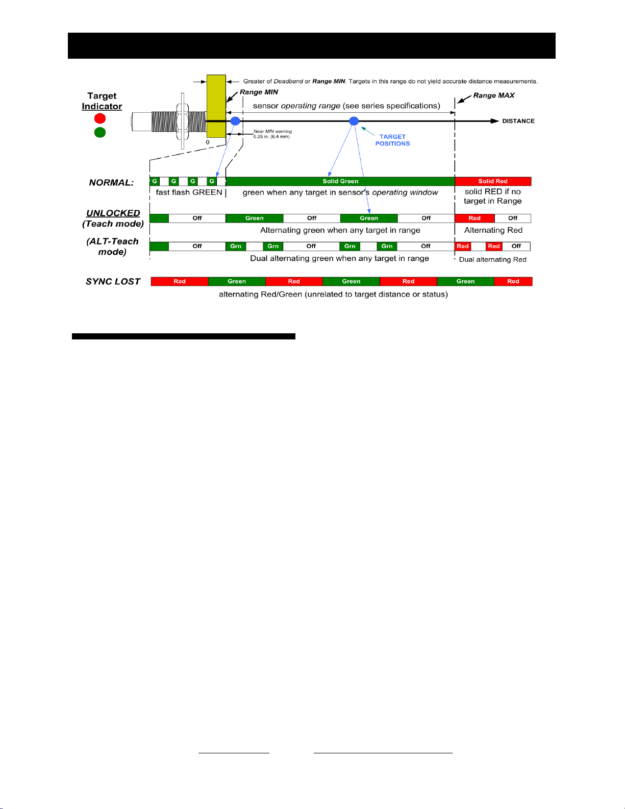
Figure 7 - Target Indicator Functions
Target Indicator
As shown in the figure above, the target indicator is
a 2-color LED and provides status for the following
purposes:
•Power ON
•Target status & near MIN
•Data communications
•“No SYNC” warning
•Unlocked status
•TEACH feedback (ToughSonic 3, 12, 14,
and 30)
Power ON Status
When sensor power is ON the target indicator will be
RED or GREEN. It may also be flashing at a slow or
fast rate under other conditions described below and
shown in figure 7.
Target Status & Near MIN
This is the primary operational purpose of the target
indicator. The target status displays follows:
•GREEN is a normal indication, indicating a
target is detected within the sensor’s
operating range
•RED indicates no target is detected within
the sensor’s operating range.
•FAST FLASH GREEN warns that the target
is within 0.25 in. (6.4 mm) of range MIN.
Unlocked Status (ToughSonic 3, 12,
14, and 30)
The sensor must be unlocked for TEACH adjustment.
When unlocked the target indicator will continue to
indicate target status (Red or Green) but will blink
slowly on and off to signify TEACH readiness. ALT-
Teach status is indicated by an alternating “double
blink”. All filters are turned OFF when unlocked.
TEACH and ALT-Teach Feedback
(ToughSonic 3, 12, 14, and 30)
When using the TEACH features to make sensor
adjustments the Target Status Indicator will SLOW
BLINK RED (unless the TEACH functions are
disabled using SenixVIEW and the sensor is not a
SYNC master or slave) as operator feedback while
the TEACH button is pressed. The user must count
these flashes, then release the TEACH button after a
specific number of flashes to complete a particular
TEACH feature. ALT-Teach feedback is indicated by
a slow “double blink”.
“No SYNC” Warning
If the SYNC feature is used (see page 32) and a slave
sensor does not detect a master SYNC input, the
slave will stop measuring and the Target Status
indicator will slowly alternate between RED and
GREEN until SYNC is restored (or the TEACH
button is used on certain models).

®
Senix Corporation, 10516 Route 116 Suite 300, Hinesburg, VT 05461 USA
Web: www.senix.com, e-mail: Technical.Support@senix.com
Page 17 of 54 –Aug 19, 2019
ToughSonic® Family Sensors –Installation & Operating Instructions
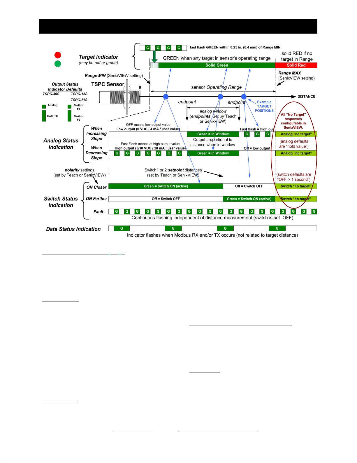
Output Status Indicators
Some ToughSonic sensors have two output status
indicators at the rear of the sensor. These indicators
can each show status of the analog, switch or serial
data interfaces, or can be turned OFF. Indicators
have default assignments and can be reassigned using
SenixVIEW. Indicator operations are shown in figure
8
In a typical installation the analog output is operating
within a user-calibrated range and the normal
indication is a continuously ON indicator. An OFF or
blinking indicator could indicate a potential problem
because the sensor is detecting a target outside the
calibrated (expected) distance range.
Default Indicator Assignments
•ToughSonic 3, 12, and 14:
Square = Analog, Rectangular = data TX
•ToughSonic 30 and 50S:
Square = Switch #1, Rectangular = Switch
#2
•ToughSonic 50RM:
No indicators
•ToughSonic 50P:
Square = data RX, Rectangular = data TX
Square Green Indicator - ■
The square status indicator can be configured using
SenixVIEW to any of the status options (analog,
switch, serial data receive, serial data transmit or
OFF). If selected for a switch it displays the status for
Switch #1.
Rectangular Green Indicator - ▐
The rectangular status indicator can be configured
using SenixVIEW to any of the status options
(analog, switch, serial data receive, serial data
transmit or OFF). If selected for a switch it displays
the status for Switch #2.
Switch Status
When a status indicator is selected as a solid state
switch, it operates as follows:
•Indicator ON if switch is ON
•Indicator OFF if switch is OFF
•Indicator blinks on and off continuously
while the switch is in a safe shutdown mode
due to over current or temperature.
The Output Selection for a Switch may be either
sinking or sourcing but the status indication is the
same. A switch is considered ON when it is
conducting current (see page 23).
Analog Status
When a status indicator is selected for analog status it
shows the current status of the analog output(s). The
analog status is the same for voltage and current loop
outputs since they share common endpoint distances.
The analog status indicator:
•is ON if the target distance is between the
two analog endpoint distances over which
the analog output is spanned, or
•is OFF if the target distance is equal to or
outside the low value endpoint distance. The
sensor output will be 0 VDC, 4 mA or the
SenixVIEW adjusted low analog output
value, or
•blinks ON-OFF if the target distance is
equal to or outside the high value endpoint
distance. The sensor output will be 5/10
VDC, 20 mA or the SenixVIEW adjusted
high analog output value.
Serial Data Status
In systems using serial data communications a status
indicator(s) can be configured using SenixVIEW to
either (a) flash upon receiving any data (regardless of
validity or baud rate), or (b) flash upon transmitting
data (responding to a valid command). A TX
indicator will also flash each time data is transmitted
in the ASCII streaming mode.
®
Senix Corporation, 10516 Route 116 Suite 300, Hinesburg, VT 05461 USA
Web: www.senix.com, e-mail: Technical.Support@senix.com
Page 18 of 54 –Aug 19, 2019
ToughSonic® Family Sensors –Installation & Operating Instructions
Figure 8 - Output Status Indicator Operations
Output Status Indicators (■&▐): Analog, switch
and/or data status is shown on the square indicator
(■) and/or rectangular indicator (▐ ). Default
assignments may be changed using SenixVIEW.
Analog status appears for current loop or voltage
outputs, and Switch Status for sinking or sourcing
switch outputs.
Analog Status: The above two analog examples
show an increasing analog slope (top) and decreasing
analog slope (bottom). An increasing slope means
the output value increases proportional to the
measured distance and vice versa. A fast flashing
analog indicator means the analog output is at the
high endpoint voltage or current output value (10
VDC, 5 VDC, 20 mA, or user value entered in
SenixVIEW). An OFF analog indicator means the
analog output is at the low endpoint voltage or
current output value (0 VDC, 4 mA, or user value
entered in SenixVIEW). The analog status is solid
green when the measurement is within the normal
(calibrated) range.
Switch Status: The indicator will light green when
the associated switch is ON. An ON switch means is
it conducting current, and an OFF switch not. A
sinking switch output that is ON will have an output
value near ground (0 volts). A sourcing switch output
that is ON will have an output value near the power
supply voltage. The three switch examples shown
above demonstrate a switch that is ON at distances
closer than the setpoint (ON closer), farther than the
setpoint (ON Farther) and a FAULT condition
(overload or over temperature). During a FAULT the
switch is turned OFF. Normal switch operation
restores automatically when the fault is removed.
Analog and Switch Outputs if No Target: If no
target is detected (target indicator is red) the analog
output will hold the last value and the switch outputs
will turn off after 1 second. These responses can be
changed in SenixVIEW by changing the “No Target
Voltage”and “No Target Current” selections.
Data Status: The status indicator will flicker ON
when the sensor receives (RX status) or responds
(TX status) to a Modbus command over the serial
data interface.
®
Senix Corporation, 10516 Route 116 Suite 300, Hinesburg, VT 05461 USA
Web: www.senix.com, e-mail: Technical.Support@senix.com
Page 19 of 54 –Aug 19, 2019
ToughSonic® Family Sensors –Installation & Operating Instructions
INTERFACES
Wires Identification
ToughSonic sensors have shielded 4-wire, 6-wire or 9-wire cables with the following wire assignments:
Wire
Color
Wire Function
ToughSonic 3, 12, and 14 Series
(6-wire cable)
ToughSonic 30 and 50 Series
(9-wire cable)
Brown
+DC input voltage (Power Input)
Blue
-DC input and signal common (Ground)
Gray (data #1)
(note 2)
RS-232 models: RS-232 out
RS-485 models: RS-485 -
Yellow (data #2)
(note 2)
RS-232 models: RS-232 in
RS-485 models: RS-485 +
Silver
Cable shield (bare stranded wire), unterminated at sensor end
Colors below are not on Serial Only models
Black
Output #1 (note 1)
4-20 mA sourcing loop (note 3)
OR Sinking Switch #1
OR Sourcing Switch #1
or OFF
Sinking Switch #1 (note 3)
OR
Sourcing Switch #1
White
Output #2 (note 1)
0-10 VDC (note 3)
OR Sinking Switch #2
OR Sourcing Switch #2
OR OFF
Sinking Switch #2 (note 3)
OR
Sourcing Switch #2
Green
These wires are not on
ToughSonic 3, 12, or 14 Sensors
Current sourcing output
Orange
Current sinking output
Violet
Voltage output
Notes:
(1) Output selection for the black and white wires of ToughSonic 3, 12, or 14 sensors are made via SenixVIEW (page 43)
(2) Output determined by sensor model. The gray and yellow wires are also used for synchronization (page32)
(3) Factory default selections(can be changed using SenixVIEW)
Table 1 - Wire Assignments
®
Senix Corporation, 10516 Route 116 Suite 300, Hinesburg, VT 05461 USA
Web: www.senix.com, e-mail: Technical.Support@senix.com
Page 20 of 54 –Aug 19, 2019
ToughSonic® Family Sensors –Installation & Operating Instructions
Ground (blue wire)
The ground wire is common to both the power supply
and the output circuits.
Cable Shield (bare wire)
The cable shield is not terminated at the sensor. This
wire should be terminated to equipment ground near
the user equipment, preferably to a single point
ground for all equipment. This is important if the
cable is lengthened and/or routed near electrically
noisy wiring or equipment.
Power Input (brown wire)
Connect a DC power supply to the DC+ (Brown) and
GND (Blue) wires. These colors conform to EU
standards. Reversing the power connections will not
damage the sensor. A power supply voltage between
15-30 VDC is recommended. A +24 VDC supply is a
commonly used standard. Target sensitivity and the
maximum voltage output value is reduced at power
supply voltages below 15 VDC. When power is
applied, the rear LED target indicator will light and
the sensor operates as described on page 30.
ToughSonic 3, 12, &14 Outputs (black
& white)
Each output can be either an analog, a switch, or
turned OFF. Analog interfaces are described on page
21 and switch interfaces on page 23. Output
selections require SenixVIEW (see page 43).
ToughSonic 30 and 50 Outputs
These models provide simultaneous 0-10 VDC, 4-20
mA sourcing, 4-20 mA sinking, and two switch
outputs. The default switch outputs are sinking (NPN
type) but may be changed to sourcing (PNP type) or
turned OFF using SenixVIEW.
Data Connections (gray & yellow)
Serial data interfaces are described on page 26. They
are used for:
•SenixVIEW PC configuration (page 42)
•Synchronization (page 32)
•User communications between the sensor
and an external data communications device
All ToughSonic serial RS-232 models can connect to
a PC USB port for SenixVIEW configuration as
shown in figure 9 with UAN-KIT-USB-232 and
optional UA-USB-232-ISO adapter,. See Software
and Interconnection (pg 15).
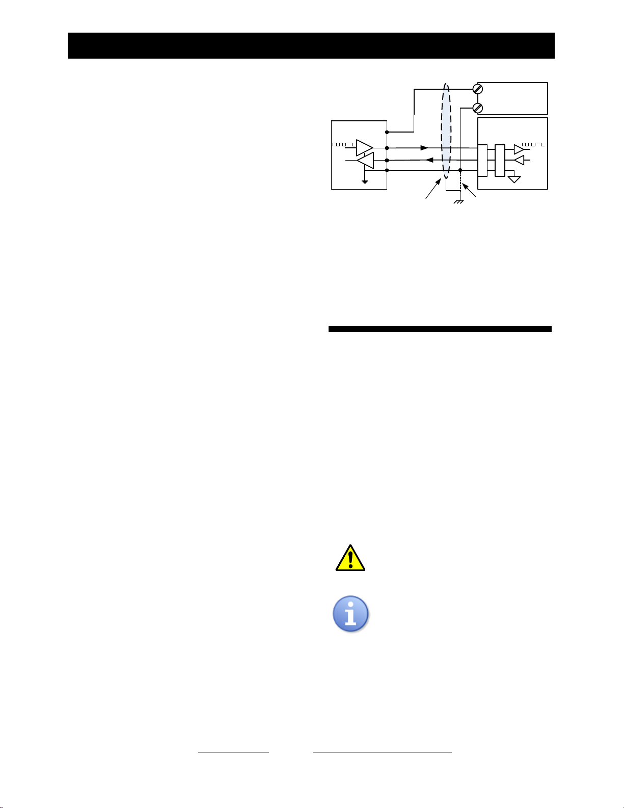
Figure 9 - RS-232 PC COM Port Connections
RS-485 models require the RS-485 interface kit,
UAN-KIT-USB-485 and UA-USB-485-ISO adaptor
for USB port connection, or the full kit UAN-KIT-
USB-485. See Software and Interconnection (pg 15).
ToughSonic 3, 12, &14
Output Selection
The ToughSonic 3, 12, &14 series sensors have two
user-selected outputs. These outputs connect via the
black and white wires of the sensor cable.
The factory default selections are a 4-20 mA current
loop connected to the black wire and a 0-10 VDC
output to the white wire. Using SenixVIEW, one or
both of these analog outputs can be changed to either
a sinking (NPN) or sourcing (PNP) switch, or can be
turned off. If turned off the associated rear status
indicator is also turned off.
Refer to Outputs & Indicators on page 43 for
information on using SenixVIEW.
Make the output selections before
connecting the sensor to equipment!
Output selections are not affected by a
TEACH 17 reset.
NOTE: Output selection is NOT
REQUIRED for ToughSonic 30 and 50 series
sensors. All outputs are independently wired and
simultaneously run.
Sensor User Equipment
(RS-232 interface)
Single point ground
optional (recommended)
DC+
(Brown)
Blue
Cable Shield
RX
GND
DB9* DB25*
+Power Supply
(24 VDC typical)
-
2
5
*Typical personal computer connections for
9 and 25-pin serial COM connectors
Yellow
RS-232
Wiring
Gray
TX 33
7
2
This manual suits for next models
5
Table of contents
Other Senix Accessories manuals


