Senlan Hope800 Series User manual

Manual for Hope800 Series High-performance Vector Control Inverter
I
Contents
Preface...................................................................................................................................1
1 Precautions.........................................................................................................................4
1.1 Safety precautions...................................................................................................................................4
1.2 Other precautions....................................................................................................................................5
2 Specifications......................................................................................................................7
2.1 Common specifications for Hope800 series .........................................................................................7
2.2 Product series specifications.................................................................................................................8
3 Installation and wiring ....................................................................................................12
3.1 Installation .........................................................................................................................................12
3.2 Removal and installation of parts.......................................................................................................13
3.2.1 Removal and installation of keypad...........................................................................................13
3.2.2 Installation of keypad on cabinet front cover .............................................................................13
3.2.3 Uninstallation/Installation of Cover and Control Panel..............................................................14
3.3 Wiring................................................................................................................................................15
3.3.1 Wiring and configuration of main circuit terminals....................................................................15
3.3.2 Wiring method...........................................................................................................................20
3.3.3 Control board terminals, jumpers and wirings............................................................................20
3.4 Methods of suppressing electromagnetic interference........................................................................24
4 Operation and commissioning ........................................................................................26
4.1 Operation and display.........................................................................................................................26
4.1.1 Keypad functions .....................................................................................................................26
4.1.2 Display status and operation of keypad......................................................................................27
4.2 Power on for the first time..................................................................................................................29
4.3 Quick commissioning............................................................................................................................29
4.3.1 Setting of common parameters......................................................................................................29
4.3.2 Quick commissioning for V/F control...........................................................................................30
4.3.3 Quick commissioning for vector control.......................................................................................30
5 Parameter table................................................................................................................31
F0: Basic Parameters................................................................................................................................31
F1: Accel/decel, start, stop and jog parameters ........................................................................................32

Manual for Hope800 Series High-performance Vector Control Inverter
II
F2: V/F control parameters ......................................................................................................................33
F3: Speed, torque and flux control parameters.........................................................................................35
F4: Digital input terminals and multistep speed.......................................................................................36
F5: Digital and relay outputs....................................................................................................................38
F6: Analog and pulse frequency terminals...............................................................................................40
F7: Process PID parameters .....................................................................................................................42
F8: Simple PLC........................................................................................................................................44
F9: Wobble frequency, counter, meter-counter and zero-servo.................................................................45
FA: Motor parameters ..............................................................................................................................46
Fb: Protection functions and advanced settings........................................................................................47
FC: Keypad operation and display settings ..............................................................................................50
Fd: Expansion options and functions........................................................................................................51
FE: Programmable unit............................................................................................................................52
FF: Communication parameters...............................................................................................................56
Fn: Factory parameter..............................................................................................................................56
FP: Fault history.......................................................................................................................................57
FU: Data monitoring................................................................................................................................58
6 Parameter description.....................................................................................................60
6.1 F0: Basic Parameters.....................................................................................................................60
6.2 F1: Accel/decel, start, stop and jog parameters..............................................................................63
6.3 F2: V/F control parameters............................................................................................................68
6.4 F3: Speed, torque and flux control parameters ..............................................................................72
6.5 F4: Digital input terminals and multistep speed.............................................................................76
6.6 F5: Digital output and relay outputs ..............................................................................................83
6.7 F6: Analog and pulse frequency terminals.....................................................................................87
6.8 F7: Process PID parameters...........................................................................................................91
6.9 F8: Simple PLC.............................................................................................................................95
6.10 F9: Wobble frequency, counter, meter-counter and zero-servo....................................................100
6.11 FA: Motor parameters..................................................................................................................105
6.12 Fb: Protection functions and advanced settings...........................................................................109
6.13 FC: Keypad operation and display settings..................................................................................115
6.14 Fd: Expansion options and functions...........................................................................................117
6.15 FE: Programmable unit ...............................................................................................................121

Manual for Hope800 Series High-performance Vector Control Inverter
III
6.16 FF: Communication parameters ..................................................................................................127
6.17 FP: Fault history..........................................................................................................................133
6.18 FU: Data monitoring ...................................................................................................................134
7 Troubleshooting .............................................................................................................137
7.1 Faults and remedies..........................................................................................................................137
7.2 Alarms and remedies........................................................................................................................140
7.3 Operation faults and remedies..........................................................................................................143
8 Maintenance and after-sale services.............................................................................145
8.1 Daily maintenance............................................................................................................................145
8.2 Periodical maintenance.....................................................................................................................145
8.3 Replacement of parts........................................................................................................................146
8.4 Storage of the inverter......................................................................................................................146
8.5 After-sale services............................................................................................................................146
9 Options ...........................................................................................................................147
9.1 Braking unit .....................................................................................................................................147
9.2 Communication component..............................................................................................................147
9.3 AC reactor........................................................................................................................................148
9.4 EMI filter and ferrite chip common-mode filter...............................................................................148
9.5 Digital I/O expansion board .............................................................................................................148
9.6 Encoder interface board(SL-PG0)....................................................................................................149
9.7 Keypad options ................................................................................................................................151
9.8 keypad mounting box.......................................................................................................................152
9.9 Analog input expansion board..........................................................................................................152

PREFACE
1
Preface
Thank you for purchasing our SenLan Hope800 series high-performance vector control inverters.
Hope800 is a new-generation inverter developed independently by the SenLan Science & Technology
Holding Corp., Ltd., featuring low noise, high performance and multiple functions. It adopts the rotor
field-oriented vector control strategy to realize high-accuracy, wide-range speed and torque control of the
motor with high reliability, powerful functions. It can be widely applied in metallurgy, petroleum, chemical
engineering, spinning, electric power, building materials, coal, medicine, food, papermaking, plastic, printing
and dyeing, hoisting, cable, washing, water supply, heating and ventilation, sewage treatment and other
industries, such as drawbenches, mixers, extruders, winding machines, compressors, fans, pumps, grinding
machines, belt conveyors, hoists and centrifuges.
Hope800’s wide application attributes to its modular design and various options, which offer the
customers integrated solutions, lower the system cost and improve the system reliability remarkably.
Furthermore, users can carry out secondary development according to their own needs.
Please carefully read and understand this manual before installing, setting, running and maintaining the
product and keep it in safety. The technical specifications for the product may alter and the contents of this
manual are subject to change without notice.
Check after unpacking
Please check the following items after unpacking the inverter. If there is anything missing, contact us or
our distributors.
Check items
Check method
If the product is exactly what
you have ordered?
Check to see if the data on the nameplate of the inverter is consistent with
those in your order form
If there is any damage of the
product?
Observe the external appearance of the product. Check to see if it has got
any damage during transportation.
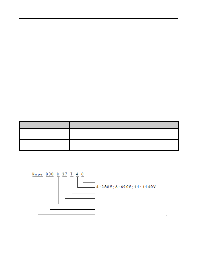
Description of inverter type
C: cabinet; default: on-hook
T: three phases; S: single phase
Rated power: 37kW
G: general type; Q: quadrant 4; H: 12 pulse waves
800: product series number
Hope: English of Chinese word "希望"
Description of Inverter Nameplate: (based on Hope800G132T4)

PREFACE
2
Safety signs
The safety signs in this manual fall into two categories:
DANGER
: indicates that errors in operation may destroy the inverter or lead to death or
heavy injury to people.
!CAUTION
: indicates that errors in operation may lead to damage to the inverter or other
devices.
Terms and abbreviations:
Name
Description
AI
Analog Input, see page 79
AO
Analog Output, see page 81
ASR
Automatic Speed Regulator, see page 60
AVR
Automatic Voltage Regulation, see page 64
EMC
Electric Magnetic Compatibility
EMI
Electric Magnetic Interference
LED
Light Emitting Diode
PFI
Pulse Frequency Input, see page 82
PFO
Pulse Frequency Output, see page 82
PID
Proportion-integration –differentiation, see page 83
PG
Pulse Generator, see page 105
PWM
Pulse Width Modulate
UP/DOWN value
A percentage value that can be adjusted by terminals and keypad / keys. It can
be used as the frequency reference (max. frequency=100%) or PID reference. See page
74
Programmable unit
A software module inside the inverter that implements the arithmetic operation, logic
operation, comparison and the like. See page 109
n(digital input)
The nth digital signal listed in the “Table of digital input functions”in page 70.
It can be used as the input of X, FWD and REV terminals, as well as the output of the
logic unit, timer and comparator.
n (digital output)
The nth digital signal listed in the “Table of digital output functions”on page 76.
It can be used as the output of the Y terminals and relays, as well as the input of the
logic unit, timer, analog multi-switch, counter and meter-counter.
n (analog output)
The nth analog signal listed in the “Table of analog output functions”on page 81

1 Precautions
3
It can be used as the output of the AO1, AO2 and PFO terminals, as well as the input of
the comparator, analog multi-switch and low-pass filter.

1 Precautions
4
1 Precautions
1.1 Safety precautions
I. Installation
Do not install the inverter at a place with or near inflammable objects, otherwise there may be a
risk of fire.
Install the inverter on flat, smooth and solid surface and keep it away from moist, heat and
condensation environment.
II. Wiring
Make sure the high-voltage indicator is off and the DC link voltage is lower than 36V, otherwise
there may be a risk of electric shock.
Make sure that the input power is completely cut off before the wiring is conducted, otherwise
there may be a risk of electric shock.
Do not connect a braking resistor between the DC+ terminals DC- to avoid fire.
The voltage of the input power terminals should not be out of the rated voltage range to avoid
damages to the inverter.
The grounding terminal(PE) of the inverter must be securely connected to earth (resistance to
earth≤10), otherwise there may be a risk of electric fire.
III. Check before switching on the power
Close the door of the inverter before turning on the power, otherwise there may be a risk of
electric shock or explosion.
Before trying to run the motor at a frequency over the rated motor frequency, make sure that the
motor and the mechanical devices can endure such a high speed.
IV. Precautions on power and operation
Check if parameters are appropriately set before commissioning.
Do not open the front cover while the input power is switched on, for the high voltage inside
may cause electric shock.
Do not handle the inverter with wet hands. That may lead to electric shock.
“Power-on auto start”is enabled before shipment from the factory. When the terminal control
and the run signal are valid, the inverter will start automatically once the power is on.
Do not control the run and stop of the inverter by switching on and off the input power.
Related parameters should be reset after parameter initialization.
If the function of restart has been set (such as auto-reset or restart after momentary power failure),
do not approach the motor or mechanical load while the inverter is waiting to restart.
V. Precautions on transport and package
Do not place more inverters than specified in the packaging box.
Do not put any heavy object on the inverter.
Do not open the cover board during transportation.
Do not apply any force on the keypad and the cover board while handling the inverter, otherwise
there may be a risk of injury to people or damage to equipment.

1 Precautions
5
VI. Disposal
Dispose the inverter as industrial waste.
The electrolytic capacitors inside the inverter may explode while burned.
Plastic components of the inverter will generate poisonous gases while burned.
1.2 Other precautions
I. About motor and mechanical load
Comparison with commercial power operation
Hope800 inverter is a voltage-type PWM motor drive. Its output voltage contains some harmonics.
Compared with the commercial power, it creates more loss and noise and leads to largrer temperature rise of
the motor.
The insulation withstands voltage of the cables and motor should be taken into account when the input
voltage is high or the motor cables are long.
Constant-torque, low-speed operation
When a common motor runs at low speed for a long time, the motor temperature will rise due to the
weakened cooling effect. So if a motor is required to operate at low speed and constant torque for a long period
of time, an inverter or the forced air cooling method must be applied.
Overload protection
If the rated capacity of the motor does not match that of the inverter, regulate the overload protection level
or adopt other protective measures so that the motor can operate safely.
Running above 50Hz
If you plan to run the motor over 50Hz, be aware that the vibration and noise will increase and make sure
that the motor bearings and mechanical devices can withstand such a high speed.
Lubrication of mechanical devices
While running at low speed for a long time, such mechanical devices as gearbox and gears may be
damaged due to weakened lubricating effect. Before you run them, check the lubrication conditions.
Load of regulative torque
Regulative torque often occurs while a load is hoisted, and the inverter often stops due to overvoltage
protection. In this case, an appropriate braking unit should be installed.
Mechanical resonant point
Certain output frequencies of the inverter may be the mechanical resonant points. To avoid these points,
place anti-vibration rubber under the base of the motor or setting the jump frequencies.
Motor insulation check before connected to the inverter
When the motor is used for the first time or reused after it has not been used for a long time, the motor
insulation must be inspected to prevent the damage to the inverter caused by the failed insulation of the motor
windings. Use a 500V voltage-type megaohm meter to measure the insulation resistance, which should be no
less than 5MΩ.
II. About inverter
Capacitor or voltage-dependent resistor for power factor improvement

1 Precautions
6
As the inverter output is of PWM voltage type, the capacitor or voltage-dependent resistor (for improving
the power factor) installed on the output side of the inverter will lead to inverter trip or damage to
components. Do remove the capacitor or the voltage-dependent resistor before using the inverter.
Installation of switching devices (e.g. contactor) on inverter output side
If a switching device like contactor is required to be installed between the inverter and the motor, make
sure the on/off operation is performed while the inverter has no output, otherwise the inverter may be
destroyed.
Frequent start and stop
For applications where frequent start and stop are needed, terminals are recommended for the control of
the start/stop of the inverter. Using the switching device (such as contactor) on the inverter input side to start or
stop the inverter frequently is prohibited. That may destroy the inverter.
Using the inverter beyond the rated value
It is not recommended to operate the inverter beyond the range of the allowable input voltage. If the
inverter has to be used beyond the range, raise or reduce the voltage via a voltage regulator.
Lightning protection
With the built-in protection of overvoltage from lightning, the inverter has certain self-protection ability
against lightning strike.
Leakage protector
The high-speed switching operation during the running of the inverter will generate high-frequency
current which sometimes causes the mis-operation of the leakage protection circuit. To address this issue,
moderately lower the carrier frequency, shorten the wires or install a leakage protector.
Observe the following points while installing the leakage protector.
1) The leakage protector should be installed on the inverter input side, preferably behind the air switch
(non-fuse circuit breaker).
2) The leakage protector should be one that is insensitive to higher harmonics or specially designed for
the inverter (sensitivity above 30mA). If a common leakage protector is selected, its sensitivity and action time
should be greater than 200mA and 0.2s respectively.
Derating of inverter
1) If the ambient temperature exceeds 40℃, the inverter should be derated as per figure 1 and external
forced cooling should be provided.
2) If the altitude is above 1000 meters, heat dissipation effect of the inverter will be poor due to thin air
thus it should be derated, with derated output and input current value shown in figure B and C;
3) If the carrier frequency is greater than the factory setting, the inverter should be derated by 5% for
every 1kHz increase.
Fig.A Fig. B Fig. C
01000
80
85
100
M
%
2000 3000 4000
0 1000
77
80
100
M
%
2000 3000 4000
Variable torque
Constant torque

2 Specifications
7
2 Specifications
2.1 Common specifications for Hope800 series
Item
Description
Input
Rated voltage and
frequency
3 phases: 380v; 50/60Hz
Allowable range
Voltage fluctuation range: ±15%; voltage unbalance: <3%;
frequency: 47~63 Hz
Output
Output voltage
3-phase, 0V~input voltage, with the error less than 5%.
Output frequency
range
V/F control: 0.00~650.00Hz
Vector control: 0.00~200.00Hz
Basic
specifications
Motor control
mode
V/F control without PG, V/F control with PG, vector control without
PG, vector control with PG, V/F separate control
Steady-state speed
precision
Vector control without PG: ≤1%
Vector control with PG: ≤0.02%
Starting torque
Not less than 150% of rated torque at 0.50Hz
Overload capacity
150%of rated current for 1 minute
Frequency
resolution
Digital reference: 0.01Hz Analog reference: 0.1%of max.
frequency
Output frequency
precision
Analog reference: : ±0.2%of max. frequency(25±10℃)
Digital reference: 0.01Hz(-10~+40℃)
Command source
Keypad, terminal and communication. They can be switched over by
terminals
Frequency
reference source
Keypad, communication, UP/DOWN value, AI1, AI2, PFI and
arithmetic unit
Auxiliary
frequency
reference
Achieves flexible frequency setting
Torque boost
Auto or manual torque boost
V/F curve
User defined V/F, linear V/F and 5 reduced-torque curves
Accel/decel
Linear or S-curve acceleration/deceleration
Jog
Jog frequency: 0.10~50.00Hz
Jog accel/decel time: 0.1~60.0s
Auto energy saving
V/F curve is optimized automatically based on the load condition,
achieving auto energy-saving run
AVR
Keeps the output voltage constant automatically when the voltage of
power grid fluctuates
Auto carrier
regulation
Carrier frequency is regulated automatically based on the load
characteristic and ambient temperature
Random PWM
Regulates the tone of the motor noise
Droop control
Applicable to cases where multiple inverters drive the same load
Momentary power
failure
Ensures uninterrupted operation by controlling the DC link voltage
DC braking
Braking time: 0.0~60.0s
Braking current: 0.0~100.0%of rated current
PFI
Highest input frequency: 50kHz
PFO
Open-collector pulse(square wave) output of 0~50kHz,
programmable
Analog input
2 channels of analog input, voltage or current type, positive or
negative
Analog output
2 channels of analog output, 0/4~20mAor 0/2~10V, programmable
Digital input
8 channels of optional multi-function digital input(leakage/source

2 Specifications
8
Item
Description
type)
Digital output
2 channels of optional multi-function digital output(leakage/source
type); 2 channels of multi-function relay output
Communication
Built-in RS485 port, supporting Modbus protocol and USS
commands
Characteristic
functions
Process PID
Two sets of PID parameters; multiple correction modes; free PID
function
Multiple PLC
modes
User can set 8 PLC run modes, with each having up to 48 stages. The
mode can be selected by terminals. PLC status can be saved at power
failure.
Multi-speed select
mode
4 selection modes. Refer to F4-17
User defined menu
30 user parameters can be defined
Parameter display
change
Can display parameters different from the default ones
Torque control
Torque/speed control can be switched by terminals. Multiple torque
setting modes.
Zero-servo
Zero-speed position can be locked
Characteristic
functions
High-speed
UP/DOWN
counter
Synchronous control, counting in production, stop contol by count
and precise position control can be realized
High-speed meter
counter
Stop control by length and length indication can be achieved
Wobble
Ensures even winding of textiles
Programmable unit
Comparator, logic unit, trigger, arithmetic unit, filter, multiple-way
switch, timer
kWh meter timer
For adjustment of optimal energy saving strategy
Protection functions
Overcurrent, overvoltage, undervoltage, input/output phase loss,
output short-circuit, overheating, motor overload, external fault,
analog input disconnection, stall prevention, etc.
Options
Braking unit, remote control box, digital I/O expansion board,
encoder interface board, analog input expansion board, keypad with
copying function or potentiometer, keypad mounting box, keypad
extension line, I/O reactor, EMI filter, Profibus-DP module, etc.
Ambient
Service site
Altitude less than 1000 meters; indoor; no direct sunlight; free of
dust, corrosive gases, inflammable gases, oil mist, water vapor,
water drops, salt mist, etc.
Temperature/humid
-10~+40℃/20~90%RH, no condensation
Storage
temperature
-20~+60℃
Vibration
Less than 5.9m/s2(0.6g)
Structure
Protection degree
IP30
Cooling method
Forced air cooling, with fan control
2.2 Product series specifications
Table of rated value of inverter: Table of
Model
Rated
capacity
(kVA)
Rated
output
current
(A)
Applicable
motor
(kW)
Model
Rated
capacity
(kVA)
Rated
output
current
(A)
Applicable
motor
(kW)
Hope800G0.4T4
1.1
1.5
0.4
Hope800
G45T4
60
91
45
Hope800G0.75T4
1.6
2.5
0.75
Hope800G55T4
74
112
55
2 Specifications
9
Model
Rated
capacity
(kVA)
Rated
output
current
(A)
Applicable
motor
(kW)
Model
Rated
capacity
(kVA)
Rated
output
current
(A)
Applicable
motor
(kW)
Hope800G1.5T4
2.4
3.7
1.5
Hope800G75T4
99
150
75
Hope800G2.2T4
3.6
5.5
2.2
Hope800G90T4
116
176
90
Hope800G4T4
6.4
9.7
4
Hope800G110T
4
138
210
110
Hope800G5.5T4
8.5
13
5.5
Hope800G132
T4
167
253
132
Hope800G7.5T4
12
18
7.5
Hope800G160
T4
200
304
160
Hope800G11T4
16
24
11
Hope800G200
T4
248
377
200
Hope800G15T4
20
30
15
Hope800G220T
4
273
415
220
Hope800G18.5T4
25
38
18.5
Hope800G250T
4
310
475
250
Hope800G22T4
30
45
22
Hope800G280T
4
342
520
280
Hope800G30T4
40
60
30
Hope800G315T
4
389
590
315
Hope800G37T4
49
75
37
Hope800G375T
4
460
705
375
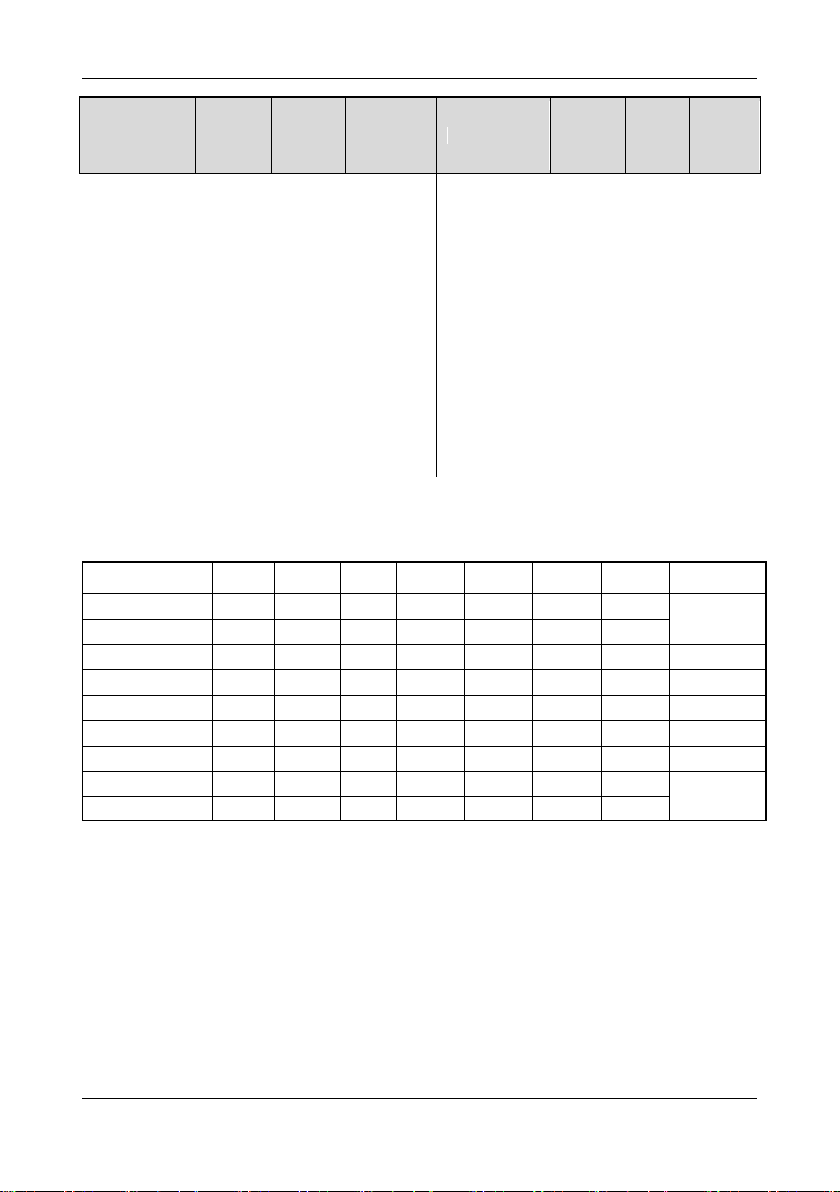
Outline and installation dimensions of HOPE800G0.4~15T4 are as follow:
Model
W(mm)
W1(mm)
H(mm)
H1(mm)
H2(mm)
d(mm)
Φ(mm)
Weight (kg)
Hope 800G0.4T4
100
87.5
180
170
5
157
4.5
2
Hope800G0.75T4
Hope800G1.5T4
Hope800G2.2T4
135
125
240
230
5
170
4.5
3
Hope800G4T4
Hope800G5.5T4
150
138
300
288
6
195
5.5
7
Hope800G7.5T4
Hope800G11T4
200
185
380
367
6
225
7
10
Hope800G15T4
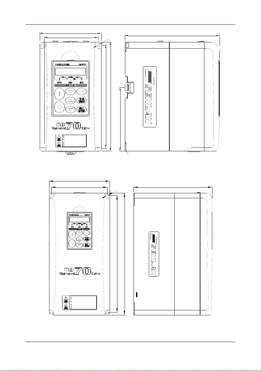
2 Specifications
10
W
A
B
H
D
d
H1
Must connect the PE terminal to the ground
Do not touch any components when the high
voltage LED is lighting
Do not connect input power to the output
terminals (U,V,W)
必须将变频器PE端子可靠接地
高压指示灯熄灭之前禁止接触机内任何部件
禁止将输入电源线接到输出端子(U,V,W)上
Boundary dimension of Hope800G18.5~375T4:
A
W
D
d
B
H
Must connect the PE terminal to the ground
Do not touch any components when the high
voltage LED is lighting
Do not connect input power to the output
terminals (U,V,W)
必须将变频器PE端子可靠接地
高压指示灯熄灭之前禁止接触机内任何部件
禁止将输入电源线接到输出端子(U,V,W)上

2 Specifications
11
Model
W
(mm)
W1
(mm)
W2
(mm)
H
(mm)
H1
(mm)
H2
(mm)
H3
(mm)
D(mm)
Φ(mm)
Weight (kg)
Hope800G18.5T4
275
160
200
530
515
7
490
285
7
22
Hope800G22T4
Hope800G30T4
Hope800G37T4
280
160
210
625
605
10
575
300
9
35
Hope800G45T4
Hope800G55T4
305
200
240
800
780
10
750
350
9
47
Hope800G75T4
50
Hope800G90T4
340
240
280
930
910
10
875
370
9
80
Hope800G110T4
82
Hope800G132T4
360
260
300
960
935
10
905
375
11
90
Hope800G160T4
460
300
400
1260
1235
10
1199
385
11
148
Hope800G200T4
150
Hope800G220T4
500
300
400
1260
1235
10
1205
385
11
175
Hope800G250T4
180
Hope800G280T4
650
400
500
1350
1320
13
1280
385
13
200
Hope800G315T4
Hope800G375T4
220
3 Installation and wiring
12
3 Installation and wiring
3.1 Installation
DANGER
1. The installation of the inverter can be performed only by qualified
professionals.
2. Do not install and run the inverter if there is any damage on the
inverter or any part is missing, otherwise there may be a risk of fire
and injury.
3. Install the inverter on a firm support that can bear its weight,
otherwise the inverter may fall and cause damage or injury.
4. Do not apply force on the keypad or cover board while handling the
inverter, otherwise the falling of keypad or cover board may cause
damage or injury.
The inverter should be installed in a room with good ventilation. The installing environment should meet
the following requirements:
1. Ambient temperature: -10~40℃. If the temperature exceeds 40℃, derate the inverter by 5% for every
one-degree increase in temperature and apply external forced cooling.
2. Altitude: not greater than 1000m. If the altitude exceeds 1000m, derate the inverter by 1% for every
100-meter increase in altitude.
3. Humidity: less than 90% RH, no condensation.
4. Vibration: less than 5.9m/s2 (0.6g)
5. Avoid installing it at a place with direct sunlight
6. Avoid installing it at a place with much dust and metal powder
7. Never install it at a place with corrosive and inflammable gases
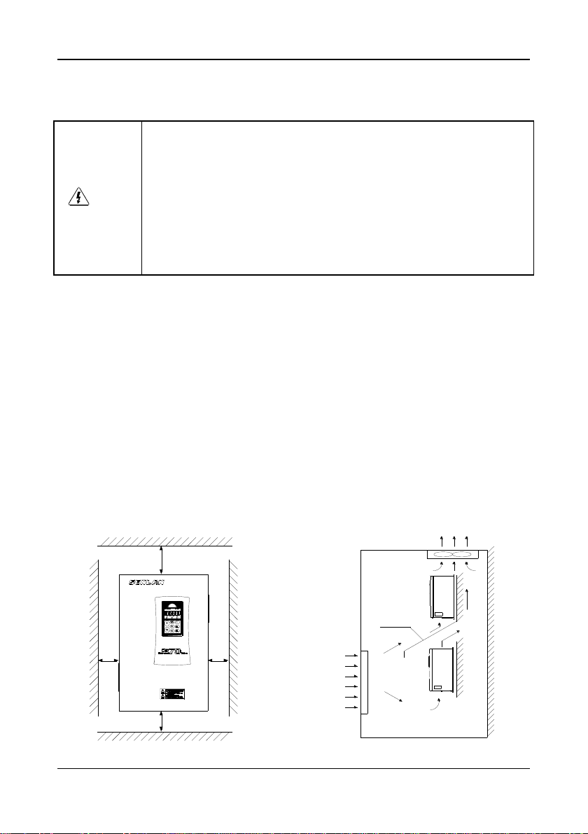
8. The inverter should be installed vertically instead of upside down, slantways or horizontally, and fixed to a
firm structure with screws. Installation, installation space and distance requirements are shown in the figure
below:
5cm or
more
5cm or
more
15cm or
more
10cm or
more
Air out
Air in
Partition
board
Inverter
Inverter
3 Installation and wiring
13
3.2 Removal and installation of parts
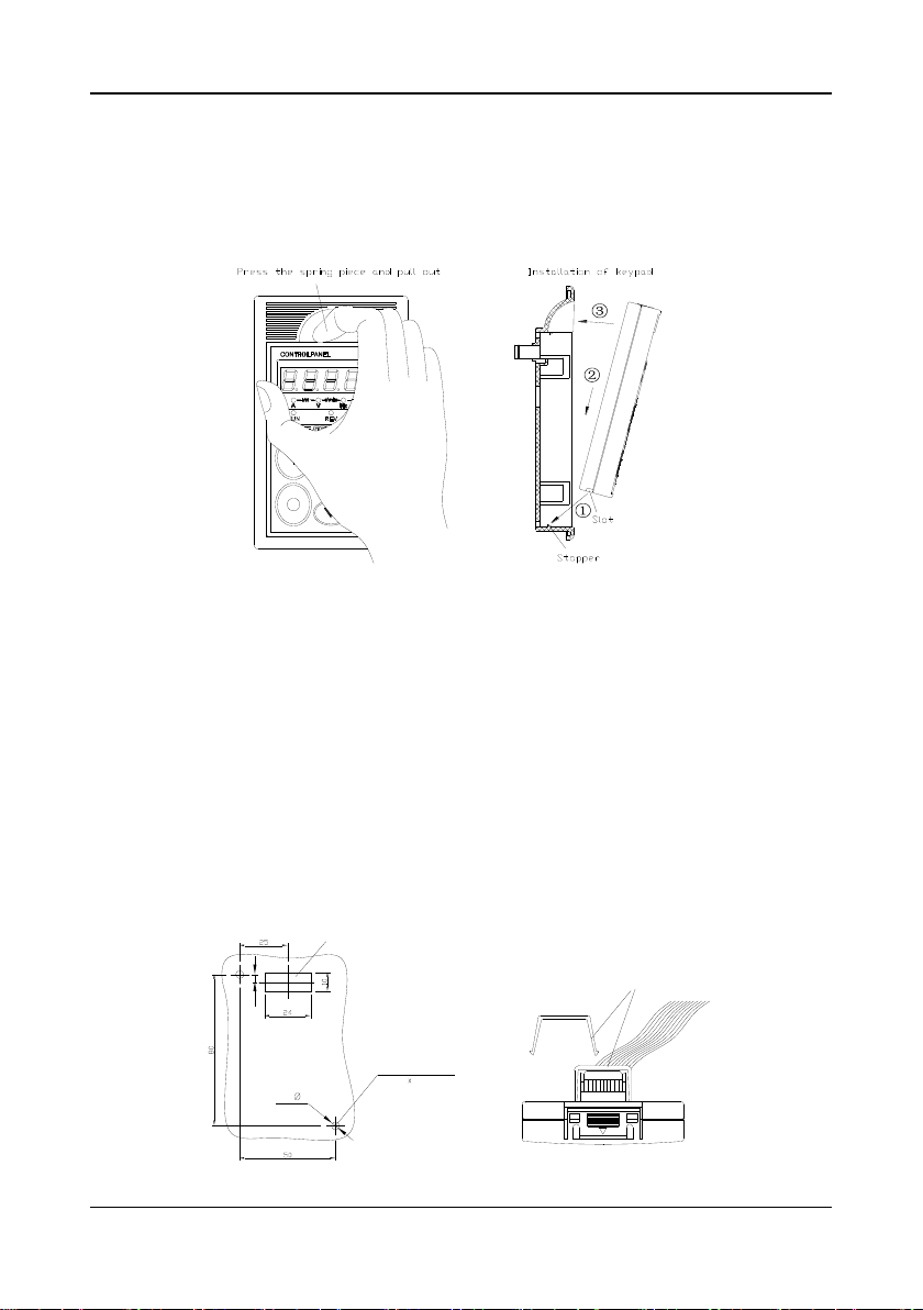
3.2.1 Removal and installation of keypad
Removal: press the spring piece on top of the keypad and pull out.
Installation: push the keypad in with the slot on its bottom aligning with the stopper on the mounting box.
3.2.2 Installation of keypad on cabinet front cover
The keypad of a Hope800 inverter can be taken off from the inverter and installed on the front cover of
the cabinet, with the keypad and inverter connected by the extension line. You can choose any one of the
following two installing methods.
Method 1: direct installation
①Make an opening on the front cover of the cabinet according to the following drawing.
②Take off the keypad and the two screws on the diagonal of the keypad. Fix the keypad to the front
cover with the two M3×14 screws shipped with the product.
③Insert one end of the extension line into the keypad and fix it with the fastener shipped with the
product. Insert the other end of the extension line into the corresponding slot on the inverter circuit
board and lock it. Close the cover board of the cabinet.
2× 4
4
Rectangle hole
for wires
Material thickness
less than 3mm
Screw hole
Two M3 14 screws
Holes for installing keypad
Holder T/SL-23(accessory) prevents the extension
line connector coming off from the keypad
3 Installation and wiring
14
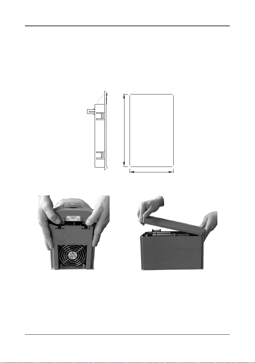
Method 2: installation via the mounting box
①Make an opening on the front cover of the cabinet according to the following drawing.
②Install the mounting box (option) onto the front cover.
③Install the keypad into the mounting box.
④Insert one end of the extension line into the keypad and the other end into the corresponding slot
on the inverter circuit board, and lock the line. Close the cover board of the cabinet.
110
67
Keypad mounting box Sizes of cabinet holes
Material thickness: 1~1.5mm
3.2.3. Uninstallation/Installation of Cover and Control Panel
During uninstallation, disassemble keypad and press the two buckles on the top of cabinet simultaneously
with two hands as shown in the left figure to take cover board down with slight upward force.
During installation, align hook at the bottom of cover board to cabinet slot and press cover board top
downward by taking bottom as pivot till hook on top enters slot; finally, install keypad as per the figure above.
The bottom, rather than shell of the product, can be held when transporting;

3 Installation and wiring
15
3.3 Wiring
DANGER
1. Wiring of the inverter can be performed only by qualified professionals.
2. Before opening the cover board of the inverter, cut the power supply and wait
for at least five minutes after all indicators on the keypad go out.
3. The wiring inside the inverter can only begin after the internal high-voltage
indicator of the inverter goes out or the voltage between terminals DC+and
DC- (measured with voltmeter) is less than 36V.
4. The inverter must be earthed reliably, otherwise there may be a risk of electric
shock or fire.
5.Shorting DC+and DC- is prohibited. That may cause fire or damage to
properties.
6.Connecting the power line with U, V or W is prohibited.
7.The inverter has passed the voltage resistance test before it is shipped from the
factory; the users need not do this test again.
8. Major loop terminals and conductor cold-pressed terminal shall be firmly
connected. Attachment DC electric reactor shall be installed if power is over
90kW.
9. All terminals must be securely connected.
10. Connecting surge absorbing capacitors or voltage-dependent resistors on the
output side of the inverter is prohibited.
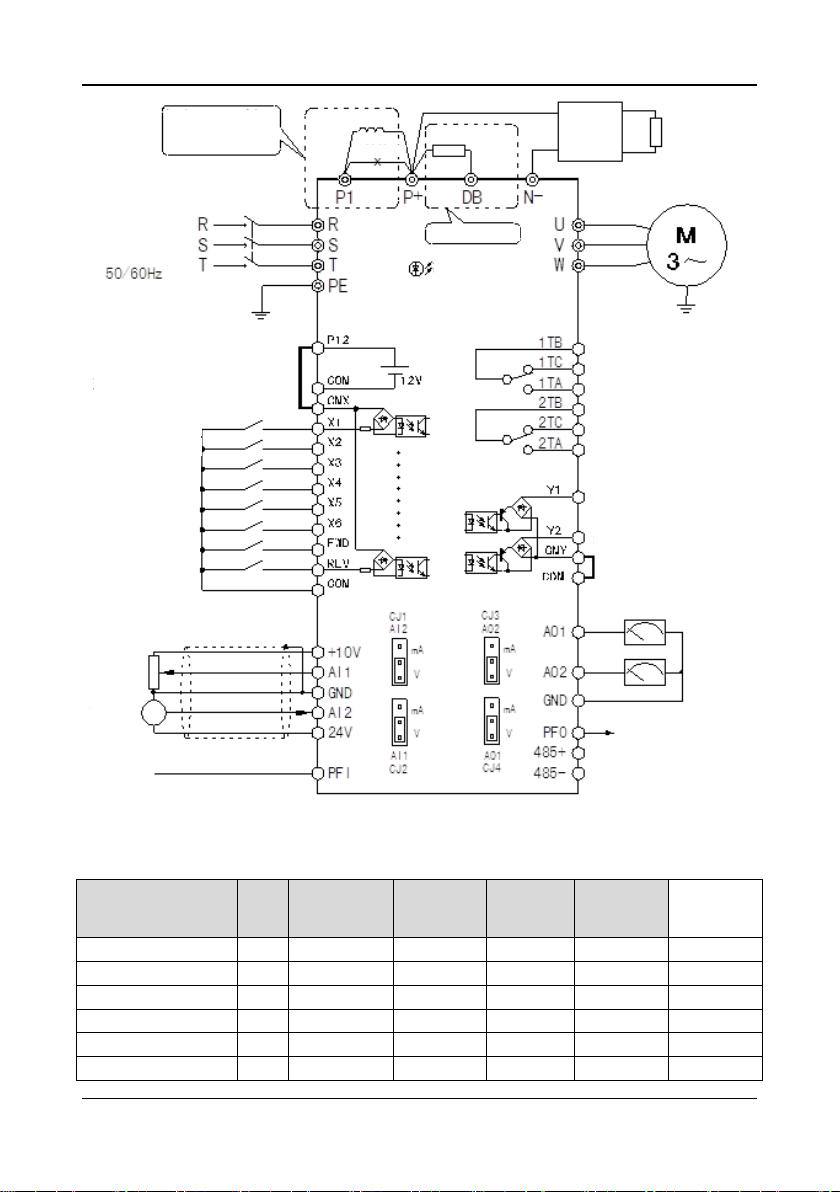
3.3.1 Wiring and configuration of main circuit terminals
The inverter and its peripherals are connected as follows:
3 Installation and wiring
16
Only for 18.5kw or more.
Remove shorting bar
between P1 and P+ before
installing DC reactor.
DC reactor
Shorting bar
Braking resistor Braking unit
3-phase input
380V power supply
Circuit breaker
Only for 15kw or less
High-voltage indicator
SB70G series inverter
Multi-function digital
input terminal and factory
configurations
Multi-function relay output
and factory configurations
Malfunction output
Multistage frequency selection 1
Shorting bar
Multistage frequency selection 2
Multistage frequency selection 3
Multistage frequency selection 4
External fault input
Fault resetting
Forward starting terminal
Reverse starting terminal
Alarm output
Multi-function digital output
and factory configurations
Inverter in operation
Frequency reached
Shorting bar
Shielding layer
Potentiometer
Sensor
Impulse frequency input
Multi-function analogy output
Operation frequency
Output current
Impulse frequency output
Frequency modulation output “operation
frequency”
RS485 port
We recommend you to choose the following air switches and main circuit wirings (copper-core
insulation wires):
Inverter model
Aire
switch
(A)
Main circuit
wiring (mm2)
AWG
Bolt
dimension
Torque
value
Wiring lug
Hope800G0.4~1.5T4
16
2.5
12
M3
2N.m
IT2.5-2
Hope800G2.2~4T4
20
4
10
M3
2N.m
IT4-3
Hope800G5.5~7.5T4
40
6
8
M4
3N.m
UT6-5
Hope800G11~15T4
63
8
6
M5
5N.m
UT10-6
Hope800G18.5~22T4
100
10
4
M8
10N.m
DT-16
Hope800G30T4
125
16
3
M8
10N.m
DT-25
This manual suits for next models
11
Table of contents
Other Senlan Inverter manuals


