manuals.online logo
Brands
  1. Home
  2. •
  3. Brands
  4. •
  5. Growatt
  6. •
  7. Inverter
  8. •
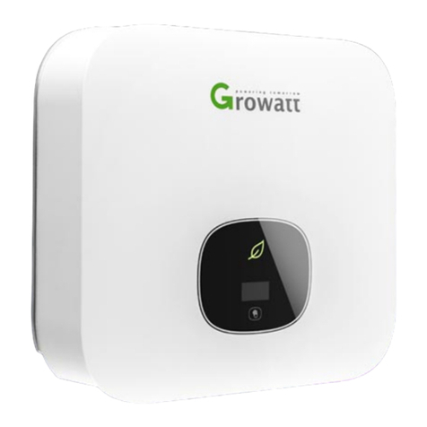
  9. Growatt MID 11-30KTL3-XH User manual

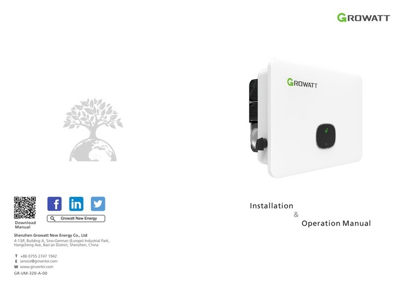
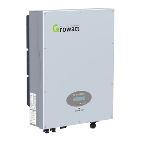
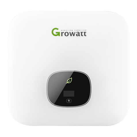
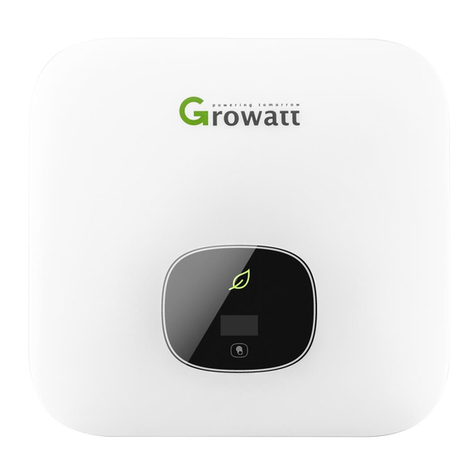
Growatt MID 11-30KTL3-XH User manual

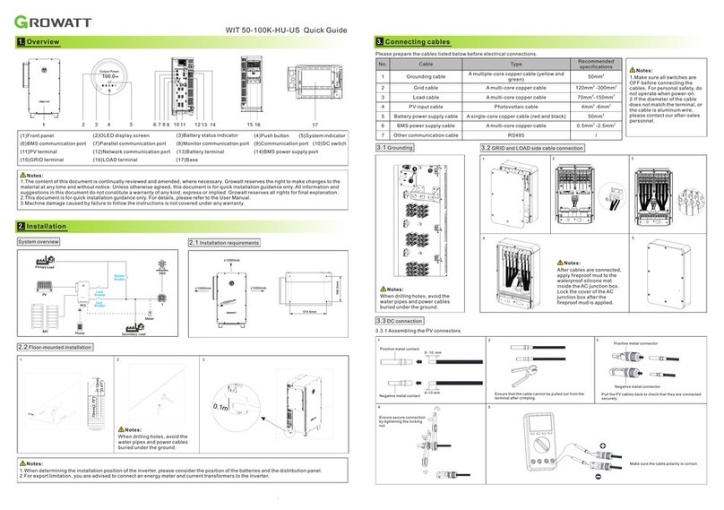
2.3InstallingthecommunicationmoduleInvertersideInvertersideInvertersideInverterside▲UpRemoveInstallPlease prepare the cables before the electrical connection.3.1Grounding3.2ConnectingtheACoutputcable3.3DCconnection3.3.1 PV input terminal installationSchéma systému 2.1 Požadavky instalace
2.2 Instalace na stěnu
Poznámka:1. Při vrtání otvorů do zdi dbejte na to, abyste se vyhnuli vodovodním trubkám a napájecím kabelům.
(1)Přední panel(2)Dotykové tlačítko (3) LCD obrazovka (4) LED indikátor
(6) Montážní deska (7) Chladič (8) DC spínač (9)Svorka FV (5)Podpěra střídače
(10)Svorka baterie
(11)USB port(12) Odvzdušňovací ventil
1. U střídačů MID 11-20KTL3-XH je svorka PV3 nahrazena vodotěsnou krytkou M12.
2. Tento dokument slouží pouze jako návod pro rychlou instalaci. Podrobnosti naleznete v uživatelské příručce.
3. Společnost Growatt nenese odpovědnost za škody způsobené nesprávnou instalací.
Poznámka:(13)COM portMakesurethecablepolarity iscorrect and voltage is less than1100V.Negative connectorGently pull the PV input cables back to ensure that they are securely connected.Ensure that the wire and the terminal are secured.
8-10mm
4mm² - 6mm²4mm² - 6mm²Positive metal contactNegative metal contactPositive metal terminalNegative metal terminal1.Please make sure that all switches are off.For safety reason, no work should be done onenergizedelectricalcircuits.2.If the diameter of the cable does not matchthe terminal, or the cable is aluminum wire,please contact our after-sales personnel.Note:
1.
Popis
2.
Instalace
3.
ElectricalconnectionMID 11-30KTL3-XH/MID 8-15KTL3-XH L stručný návod
14131211108956723421(14)Svorka AC 218260100≥500mm≥500mm579
433231
No.CableTypeRecommendedspecification1PE cableAinglemulti-coreyellow-greencable6mm²-10mm²2ACoutputcableTwo or three multicoloredmulti-core copper cables8mm²-10mm²3PV input cablePV cable4mm²-6mm²4CommunicationcableRS485/
1.Thewaterproofcapmustbeappliedwiththefireproofmudtopreventwater.2. For XH L series inverters, you do not need to connect the N line.Note:
2.3 Instalace komunikačního modulu
Strana střídače
Strana střídače Strana střídače
Strana střídače
VyjmutíInstalace
Před elektrickým připojením připravte kabely.
3.1 Z emnění 3.2 Připojení výstupního kabelu AC
3.3 Zapojení DC
3.3.1 Instalace vstupního terminálu FV
System overview2.1Installationrequirements2.2Wall-mountedinstallationNote:1.When drilling holes in the wall, avoid the water pipes and power cables.(1)Frontpanel(2)Touchbutton(3)LCDscreen(4)LEDindicator(5)Casefeet(6)Mountingplate(7)Heatsink(8)DCswitch(9)PV terminal(10)Battery terminal(11)USB port(12)Ventvalve1. For MID 11-20KTL3-XH inverters, the PV3 terminal is replaced by a M12 waterproof cap.2. This document serves as a guide for quick installation only. For details, please refer to the User Manual.3. Growatt shall not be liable for any damages caused by improper installation.Note:(13)COMportZkontrolujte správnou polaritu
kabelu a zda je napětí nižší než
1100 V.
Záporný konektor
Opatrně zatáhněte za vstupní kabely FV, abyste se ujistili,
že jsou spolehlivě připojeny.
Ujistěte se, že jsou vodič a svorka upevněny.
8-10mm
4mm² - 6mm²4mm² - 6mm²Kladný kovový kontakt
Záporný kovový kontakt
Kladná kovová svorka
Záporná kovová svorka
1.Ujistěte se, že jsou všechny spínače vypnuté. Z
bezpečnostních důvodů by se neměly provádět
žádné práce na elektrických obvodech pod
napětím.
2.Pokud průměr kabelu neodpovídá svorce nebo
se jedná o hliníkový drát, obraťte se na náš
poprodejní personál.
Poznámka:
1.
Overview
2.
Installation
3.
Elektroinstalace
MID 11-30KTL3-XH/MID 8-15KTL3-XH L Quick Guide14131211108956723421(14)ACterminal218260100≥500mm≥500mm579
433231
Č.Kabel TypDoporučené parametry
1
PE kabel Jeden vícežilový
žlutozelený kabel
6mm²-10mm²
2
AC výstupní kabel Dva nebo tři vícebarevné
vícežilové měděné kabely
8mm²-10mm²
3
Vstupní kabel FV FV kabel
4mm²-6mm²
4
Komunikační kabel
RS485
/
1. Vodotěsná krytka musí být aplikována s těsnícím silikonem, aby bylo zabráněno působení vody.
2. U střídačů řady XH L nemusíte připojovat vedení N.
Poznámka:
GR-UM-319-A-00You can view information by pressing the button.
SymbolDescriptionExplanationTouchbuttonSingletapSwitch the display interface or increase the value by oneDoubletapAccess the settings or confirm your settingTripletapReturn to the previous display interfaceLong press for 5sRestore to factory settingsInverter status indicatorRedFaultGreenNormaloperationFlashingredWarningThe LCD screen displays the basic information about the inverter,including PV/AC voltage, PV power, AC current, the total power andcapacity.
Shenzhen Growatt New Energy Co., Ltd4-13/F, BuildingA, Sino-German (Europe) Industrial Park,HangchengAve,Bao’anDistrict,Shenzhen,China+8675527471942www.ginverter.comTE service@ginverter.comW1.Před instalací FV svorky překontrolujte, zda
vstupní napětí a proud FV nepřekračují limity
MPPT.
2.Při připojování kladné a záporné FV svorky ke
střídači dbejte na správnou polaritu.
3.Ujistěte se, že uslyšíte zvuk "cvaknutí", který
signalizuje pevné připojení. Opatrným tahem
zpět se ujistěte, že jsou kabely spolehlivě
připojeny.
3.3.3 Z apojení komunikačního kabelu
Č.Přijatelný stav Č.Přijatelný stav
1
Střídač je nainstalován správně, důkladně a spolehlivě.
6
Komunikační kabel RS485 je správně a pevně nainstalován.
2
Kabely PE jsou řádně a bezpečně připojeny.
7
Stahovací pásky jsou dobře upravené, bez ostrých hran.
3
Všechny spínače jsou v pozici OFF.
8
Všechny exponované svorky jsou dobře chráněny a nejsou zde
žádné volné porty.
4
Všechna elektrická připojení jsou řádná a zajištěná.
9
Odstraňte zbytky po instalaci.
5
Kabelové vedení je přijatelné a splňuje všechny požadavky.
Není použit žádný roztřepený nebo prasklý vodič. DownloadManualGrowatt New Energy3.3.2 Zapojení svorek FV/BAT
Následující schémata znázorňují způsob připojení měřiče EASTRON (TOM-E) a Backup Boxu ke střídači:
Note:
ExporlimitOFFONPassword123
Settings
GeneralAdvancedMeterExportLimitRateXXX.X%OKFor regions where the local grid company poses restrictions on the power output of your solar system, we introduce the concept ofExport Limit Rate, which refers to the ratio ofthe output power to the rated power of theinverter. For example, if the local gridcompany permits only 4kW from your 5kWsystem, then the Export Limit Rate for the 5kWinverter would be 80%.Before turning the inverter on, please make sure the PV input voltage and current are within the MPPT limits.Follow the steps below to turn the inverter on:1.Switch on the built-in DC switch at the bottom of the inverter.2.Switch on the PV Array and DC isolator next to your inverter. If the switch is not available, skip this step.3.Switch on the Solar AC isolator if the inverter is more than 3 meters away from your switchboard.4.Switch on the solar supply main switch in the switch board.To shut down your system, follow the reverse order of the steps mentioned above.Pokud je připojen Backup boxu,
povolte jej při konfiguraci střídače.
Podrobnosti naleznete v části 9.3.3
v uživatelské příručce
MID 11-30KTL3-XH.
Poznámka:485B4485A4Pin17Pin18Pin5Pin6
485A2485B2
COM PortPin5Pin6COM Port
485A2485B2
4.
Zapojení měřiče a Backup Boxu
5.
Kontrola instalace
6.
Powering on/off the inverter
7.
Status of PV grid inverter
8.
Export limitation setting
9.
Service and contact
Poznámka:
Strana střídače
Strana střídače
1. WKomunikační kabel nepřipojujte k portům Port 15 a Port 16. Funkci dalších
portů naleznete ve výše uvedené tabulce.
2. Baterie musí být připojena k port)m 9 a 10
Poznámka:
Č.
RRCR
popis
Činný
výkon
11
K1-out
0%
12
K2-out
30%
13
K3-out
60%
14
K4-out
100%
15
Zemnění
/
16
/
/
Č.Popis Funkce
1
+12V
Suchý kontakt: výkon
jakéhokoli externího vedení
připojeného k němu by
neměl být větší než 2 W.
2
COM
3
RS485A1
Komunikační port
RS485
4
RS485B1
5
RS485A3
Komunikační port
měřiče
6
RS485B3
7
RS485A2
Komunikační port baterie
8
RS485B2
9
BAT.EN+
Signál probuzení baterie
10
BAT.EN-
11
DRM1/5
Vstup reléového kontaktu 1
12
DRM2/6
Vstup reléového kontaktu 2
13
DRM3/7
Vstup reléového kontaktu 3
14
DRM4/8
Vstup reléového kontaktu 4
15
REF/GEN
GND
16
DRM0/COM
/
21
BOX.EN+
Identifikační signál
Backup boxu
22
BOX.EN-
23
RS485A4
Komunikace
Backup boxu
24
RS485B4
27
RS485A2
Komunikační port baterie
2
28
RS485B2
29
BAT.EN+
Signál probuzení
baterie 2
30
BAT.EN-
GR-UM-319-A-00Stisknutím tlačítka zobrazíte informace.
Symbol
Popis Vysvětlení
Dotykové tlačítko
Jediné klepnutí Přepnutí rozhraní displeje nebo
zvýšení hodnoty o jedna
Dvojí klepnutí Přístup k nastavení nebo potvrzení
nastavení
Tři klepnutí Návrat k předchozímu rozhraní
displeje
Dlouhé stlačení 5sObnovení továrního nastaven
Indikátor stavu střídače
Červená Porucha
Zelená Normální provoz
Červené blikání Varování
Na displeji LCD se zobrazují základní informace o střídači, včetně napětí
PV/AC, výkonu FV, proudu AC, celkový výkon a kapacita.
Shenzhen Growatt New Energy Co., Ltd4-13/F, Building A, Sino-German (Europe) Industrial Park,Hangcheng Ave, Bao’an District, Shenzhen, ChinaT +86 755 2747 1942E [email protected]W www.ginverter.com1.Before installing the PV terminal,pleasedouble-check that the PV input voltage andcurrentdonotexceedtheMPPTlimits.2.Ensure the correct polarity whenconnecting the positive and negative PV terminals to the inverter.3.Ensure that you hear a "click" soundwhich indicates a robust connection. Gently pull the cables back to ensure that they aresecurely connected.3.3.3Connectingthecommunicationcable
No.AcceptancecriteriaNo.Acceptancecriteria1The inverter is installed correctly, firmly and reliably.6The RS485 communication cable is installed correctly and firmly.2The PE cables are properly and securely connected.7The cable ties are well-trimmed, without any sharp edges3All switches are OFF.8All exposed terminals are well protected and there are no vacantports.4All electrical connections are correct and secured.9Remove the installation residues.5The cable wiring is reasonable and meets allrequirements. No frayed or cracked wire is used.
Stažení
návodu Growatt New Energy3.3.2ConnectingthePV/BATterminalsThe following diagrams illustrate the way to connect the EASTRON meter (TOM-E) and the Backup Box to the inverter:ExporlimitOFF ONPassword123
Settings
GeneralAdvancedMeterExport Limit RateXXX.X%OKPro regiony, kde místní rozvodná společnost
omezuje výstupní výkon solárního systému,
zavádíme pojem Export Limit Rate, který se
vztahuje k poměru výstupního výkonu a
jmenovitého výkonu střídače. Například pokud
místní rozvodná společnost povolí z vašeho 5kW
systému pouze 4 kW, pak by Export Limit Rate
pro 5kW střídač činil 80 %.
Před zapnutím střídače se ujistěte, že vstupní napětí a proud fotovoltaické elektrárny jsou v mezích MPPT.
Při zapínání střídače postupujte podle následujících kroků:
1.Zapněte zabudovaný DC spínač ve spodní části střídače.
2.Zapněte FV pole a DC izolátor vedle střídače. Pokud spínač není k dispozici, tento krok přeskočte.
3.Pokud je střídač vzdálen více než 3 metry od vašeho rozvaděče, zapněte solární oddělovač AC.
4.Zapněte hlavní spínač solárního napájení v rozvaděči.
Chcete-li systém vypnout, postupujte v opačném pořadí výše uvedených kroků.
If a backup box is connected, please enable it when configuring the inverter. For details, please refer to Section 9.3.3 in the MID 11-30KTL3-XH User Manual. Note:485B4485A4Pin17Pin18Pin5Pin6
485A2485B2
COM PortPin5Pin6COM Port
485A2485B2
4.
Connecting the Meter and the Backup Box
5.
Post-installation check
6.
Spuštění a vypnutí střídače
7.
Stav FV střídače
8.
Nastavení omezení exportu
9.
Servis a kontakt
Note:
The Inverer SideThe Inverer Side1.Whenconnectingthecommunicationcable,donotconnecttoPort15andPort16.For other port definitions,please refer to the table above.2.Whenconnectingtothebattery,Port9andPort10mustbeconnected.
Note:
No.RRCRDescriptinActivePower11K1-out0%12K2-out30%13K3-out60%14K4-out100%15Relayscommonnode/16//No.DescriptionFunction1+12VDry contact:the power of any external wiringconnectedtoitshouldnot be greater than 2W2COM3RS485A1RS485communicationport4RS485B15RS485A3Meter communicationport6RS485B37RS485A2Battery communicationport8RS485B29BAT.EN+Battery wake-up signal10BAT.EN-11DRM1/5Relay contact 1 input12DRM2/6Relay contact 2input13DRM3/7Relay contact 3 input14DRM4/8Relay contact 4 input15REF/GENGND16DRM0/COM/21BOX.EN+Backup box identificationsignal22BOX.EN-23RS485A4Backup box communication24RS485B427RS485A2Battery communicationport228RS485B229BAT.EN+Battery wake-upsignal230BAT.EN-
SOLSOL s.r.o.
Králova 298/4, Brno, 616 00, ČR
[email protected]
www.solsol.cz

This manual suits for next models

1

Other Growatt Inverter manuals

Growatt MAX 175KTL3-X HV User manual

Growatt

Growatt MAX 175KTL3-X HV User manual

Growatt 10000HY User manual

Growatt

Growatt 10000HY User manual

Growatt MID 1 7 KTL3-X1 User manual

Growatt

Growatt MID 1 7 KTL3-X1 User manual

Growatt SPF 3000TL LVM User manual

Growatt

Growatt SPF 3000TL LVM User manual

Growatt WIT 28-55K-A-US L2 User manual

Growatt

Growatt WIT 28-55K-A-US L2 User manual

Growatt MIN 3000TL-XH-US User manual

Growatt

Growatt MIN 3000TL-XH-US User manual

Growatt MOD TL3-XH Series User manual

Growatt

Growatt MOD TL3-XH Series User manual

Growatt MID 11-30KTL3-XH User manual

Growatt

Growatt MID 11-30KTL3-XH User manual

Growatt MIN 2500TL-XA User manual

Growatt

Growatt MIN 2500TL-XA User manual

Growatt MOD 3000TL3-XH User manual

Growatt

Growatt MOD 3000TL3-XH User manual

Growatt 2000HF User manual

Growatt

Growatt 2000HF User manual

Growatt MOD 3000TL3-X User manual

Growatt

Growatt MOD 3000TL3-X User manual

Growatt MID 50KTL3-X2 User manual

Growatt

Growatt MID 50KTL3-X2 User manual

Growatt SPF-3500ES User manual

Growatt

Growatt SPF-3500ES User manual

Growatt 8000TL3-S User manual

Growatt

Growatt 8000TL3-S User manual

Growatt SPH Series User manual

Growatt

Growatt SPH Series User manual

Growatt Grid User manual

Growatt

Growatt Grid User manual

Growatt MIN 3K-11.4KTL-XH-US User manual

Growatt

Growatt MIN 3K-11.4KTL-XH-US User manual

Growatt MIN 2500TL-X User manual

Growatt

Growatt MIN 2500TL-X User manual

Growatt 10000UE User manual

Growatt

Growatt 10000UE User manual

Growatt TL3-X Series User manual

Growatt

Growatt TL3-X Series User manual

Growatt MOD 3-15KTL3-X User manual

Growatt

Growatt MOD 3-15KTL3-X User manual

Growatt SPF 4000T DVM-MPV User manual

Growatt

Growatt SPF 4000T DVM-MPV User manual

Growatt SPF 3500 ES User manual

Growatt

Growatt SPF 3500 ES User manual

Popular Inverter manuals by other brands

Black & Decker PI100ASB instruction manual

Black & Decker

Black & Decker PI100ASB instruction manual

Sungrow SG50KTL-M-20 Quick installation guide

Sungrow

Sungrow SG50KTL-M-20 Quick installation guide

kobi SUNFLASH 100 quick start guide

kobi

kobi SUNFLASH 100 quick start guide

Huawei SUN2000-42KTL user manual

Huawei

Huawei SUN2000-42KTL user manual

SolarEdge EV Series installation guide

SolarEdge

SolarEdge EV Series installation guide

Eaton M-Max series user manual

Eaton

Eaton M-Max series user manual

Wagan Elite 1000W user manual

Wagan

Wagan Elite 1000W user manual

Fortress Power FP-ENVY-8K Integration guide

Fortress Power

Fortress Power FP-ENVY-8K Integration guide

Vector VEC411 User's manual & warranty information

Vector

Vector VEC411 User's manual & warranty information

Yamaha EF7200DE, EF7200D owner's manual

Yamaha

Yamaha EF7200DE, EF7200D owner's manual

SMA SUNNY BOY 3000TL Single Tracker Quick installation

SMA

SMA SUNNY BOY 3000TL Single Tracker Quick installation

Rentech Jaguar 1.2K user manual

Rentech

Rentech Jaguar 1.2K user manual

SOLIS S6-EH1P3.8K-H-US user manual

SOLIS

SOLIS S6-EH1P3.8K-H-US user manual

Mitsubishi Electric FR-A8AR instruction manual

Mitsubishi Electric

Mitsubishi Electric FR-A8AR instruction manual

Ampt V600-32-32 installation manual

Ampt

Ampt V600-32-32 installation manual

enphase IQ 7 Installation and operation manual

enphase

enphase IQ 7 Installation and operation manual

POWER ON BOARD VEC550POB Owner's manual & warranty

POWER ON BOARD

POWER ON BOARD VEC550POB Owner's manual & warranty

DSPM Defender Mini manual

DSPM

DSPM Defender Mini manual

manuals.online logo
manuals.online logoBrands
  • About & Mission
  • Contact us
  • Privacy Policy
  • Terms and Conditions

Copyright 2025 Manuals.Online. All Rights Reserved.