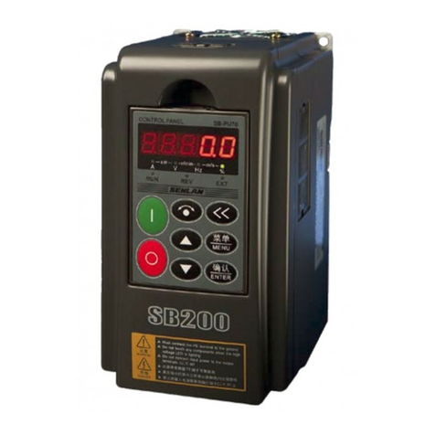
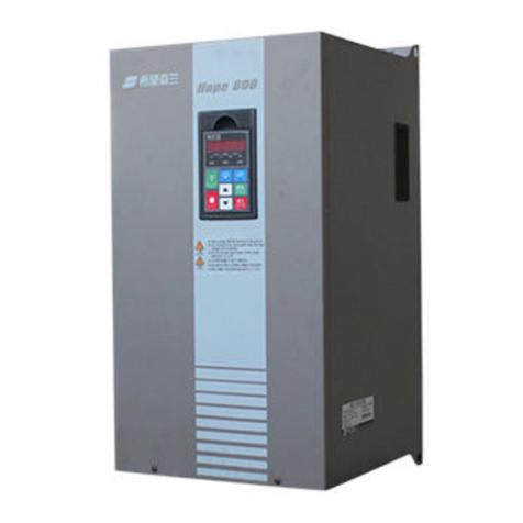
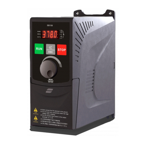
Senlan SLANVERT Hope530 Series User manual


I
Preface
1
2
3
4
5
6
7
8
9
Content
Preface...................................................................................................................................1
1. Safety and Precautions.....................................................................................................3
1.1 Safety Precautions.......................................................................................................................................3
1.2 Precautions..................................................................................................................................................4
2. Product Specification........................................................................................................6
2.1 General Technical Specification of Hope530 Series Inverter.....................................................................6
2.2 Product Series Specification .......................................................................................................................7
3. Installation and Wiring ..................................................................................................13
3.1 Inverter Installation...................................................................................................................................13
3.1.1 Installation Environment..................................................................................................................13
3.1.2 Installation Spacing and Direction...................................................................................................14
3.1.3 Complete Installation of Each Model ..............................................................................................16
3.1.4 Disassembly and Installation of Cover Plate ...................................................................................21
3.2 Wiring of the Inverter................................................................................................................................24
3.2.1 Main Circuit Terminal Wiring and Configuration ...........................................................................25
3.2.2 Incoming and Outgoing Form of Lines of the Inverter....................................................................34
3.2.3 Control board Terminal, Jumper and Wiring ...................................................................................37
3.3 Suppression Method for Inverter Electromagnetic Interference ..............................................................42
4. Inverter Operation and Test Run..................................................................................44
4.1 Inverter Operation and Display.................................................................................................................44
4.1.1 Functions of Operation Panel...........................................................................................................44
4.1.2 Display Status and Operations on the Operations Panel..................................................................46
4.2 First Energization......................................................................................................................................47
4.3 Quick Commissioning Guidelines............................................................................................................47
4.3.1 Settings for Public Parameters of Each Control Mode....................................................................47
4.3.2 V/F Control Quick Commissioning .................................................................................................48
4.3.3 Vector Control Quick Commissioning.............................................................................................48
5. List of Functional Parameters .......................................................................................49
F0 Basic Parameters........................................................................................................................................49
F1 Acceleration & Deceleration, Starting, Stopping and Jogging Parameters...............................................50
F2 V/F Control Parameters .............................................................................................................................52
F3 Speed, Torque and Flux Control Parameters.............................................................................................53
F4 Digital Input Terminal and Multi-Speed....................................................................................................54
F5 Digital Output and Relay Output Settings.................................................................................................56
F6 Analog and Pulse Frequency Terminal Settings........................................................................................58
F7 Process PID Parameters.............................................................................................................................61
F8 Simple PLC................................................................................................................................................63
F9 Wobble Frequency, Counter, Length Counter, Zero Servo .......................................................................64
FA Motor Parameters ......................................................................................................................................65
Fb Protection Function and InverterAdvanced Settings................................................................................66
FC Keyboard Operation and Display Settings................................................................................................68
Fd Retained by the manufacturer....................................................................................................................70
FE Programmable Unit ...................................................................................................................................70
FF Communication Parameters.......................................................................................................................74
Fn Manufacturer's Parameters.........................................................................................................................74
FP Fault Records.............................................................................................................................................75
FU Data Monitoring........................................................................................................................................76
6. Detailed Explanation of Functional Parameters ..........................................................79
6.1 F0 Basic Parameters..................................................................................................................................79
6.2 F1 Acceleration & Deceleration, Starting, Stopping and Jogging Parameters.........................................83
6.3 F2 V/F Control Parameters .......................................................................................................................88

II
6.4 F3 Speed, Torque and Flux Control Parameters.......................................................................................91
6.5 F4 Digital Input Terminal and Multistage Speed......................................................................................94
6.6 F5 Digital Output and Relay Output Settings.........................................................................................104
6.7 F6 Analog and Pulse Frequency Terminal Settings................................................................................108
6.8 F7 Process PID Parameters.....................................................................................................................115
6.9 F8 simple PLC.........................................................................................................................................120
6.10 F9 Textile Wobble Frequency, Counter, Length Counter, Zero Servo and Position Control...............124
6.11 FA Motor Parameters ..........................................................................................................................130
6.12 Fb Protection Function and InverterAdvanced Settings......................................................................133
6.13 FC Keyboard Operation and Display Settings......................................................................................139
6.14 FE Programmable Unit .........................................................................................................................140
6.15 FF Communication Parameters.............................................................................................................147
6.16 FP Fault Record.....................................................................................................................................152
6.17 FU Data Monitoring..............................................................................................................................154
7. Troubleshooting and Exception Handling ..................................................................157
7.1 Faults of Inverter and Solutions..............................................................................................................157
7.2 Alarms of Inverter and Solutions............................................................................................................161
7.3 Abnormal Operation of the Inverter and Solutions.................................................................................163
8. Maintenance and After-sales Service...........................................................................165
8.1 Daily Care and Maintenance...................................................................................................................165
8.2 Regular Maintenance ..............................................................................................................................165
8.3 Replacement for Vulnerable Parts of Inverter ........................................................................................166
8.4 Storage of the Inverter.............................................................................................................................166
8.5 After-sale Service....................................................................................................................................166
9. Optional Accessories.....................................................................................................168
9.1 Brake Assembly ......................................................................................................................................168
9.2 Communication Components..................................................................................................................169
9.3 AC Reactor..............................................................................................................................................172
9.4 EMI Filters and Ferrite Common Mode Filters......................................................................................172
9.5 Digital I/O Expansion Board ..................................................................................................................172
9.6 Encoder Interface Board .........................................................................................................................174
9.7 Operation Panel Option...........................................................................................................................176
9.7.1 Functions of the operator panel......................................................................................................177
9.7.2 Removal and Installation of Operation Panel ................................................................................179
9.7.3 Installation of the Operation Panel on the Cabinet Panel ..............................................................180
9.8 Analog I/O Expansion Board..................................................................................................................181
9.9 Flush Mounted Lanyards ........................................................................................................................182
9.10 Wiring Aid Kit.......................................................................................................................................189
9.10.1 Cable Holder.................................................................................................................................189
9.10.2 Wiring Board ................................................................................................................................189
9.11 Protective Cover....................................................................................................................................190

1
Preface
Preface
Thank you for purchasing SENLAN Hope530 high-performance vector control inverter.
The Hope530 series inverter is a new generation of low-noise, high-performance and multi-function inverter
independently developed by Hope Senlan Science & Technology Holding Co., Ltd. It adopts the
rotor-magnetic-field-oriented vector control mode to achieve high torque of motor, high precision, wide range speed
regulation, high reliability and powerful functions. It is widely used in metallurgy, petroleum, chemical industry, power
industry, building materials, coal, medicine, food, papermaking, plastic, textile industry, printing & dyeing, lifting,
washing, cable, packing, machinery, ceramics, water supply, centrifuge, conveyor, dehydrator, wastewater treatment,
heating & ventilating industry, as well as drawbench, agitator, extruder, winding machine, compressor, fan pumps,
grinding miller, conveyor, hoister, centrifuge and so on.
This Manual provides users with installation wiring, parameter setting, daily maintenance, fault diagnosis and
troubleshooting, etc. Before installing, setting up, running and maintaining the inverter, please be sure to read all the
contents of the User Manual of this product in detail, memorize the relevant knowledge and safety precautions of the
inverter, and ensure the correct use and give full playto its superior performance. Technical specification of this product
may change without prior notice. The Manual of this product shall be properly kept until the inverter is scrapped.
Notes for Unpacking Inspection
When unpacking, please confirm the following items carefully. If there is any problem, please contact our company or
the Supplier directly.
Confirmation Item
Validation Methods
Is it in line with your order?
Confirm whether the nameplate on the side of inverter is consistent with your
order.
Is there any damage to the product?
Check the overall appearance of the product to confirm whether it is damaged
during transportation.
Model description of the inverter
Hope 530 G 30 T 4 B L
T:三相
额定功率:30kW
530:产品系列号
Hope:希望英文
4:380V
B:内置制动单元
G:通用型
L:内置直流电抗器
L: built-in DC reactor
B: built-in brake unit
T: three phases
Rated power: 30kW
G: general type
530: series number of the product
Hope: English word of '希望'

2
Preface
Description on inverter nameplate (taking Hope530G55T4 as an example)
Definition of Safety Signs
For safety-related contents in this manual, please use the following signs, and the contents with safety signs must
be followed.
: Wrong use or operation not according to the requirements may cause damage to
the inverter or casualties.
!
: Operation not according to the requirements may result in abnormal operation of
the system. In serious cases, it may cause inverter or mechanical damage.
The comparison table of some terms and abbreviations is as follows:
Name
Meaning and Description
AI
Analog Input, see page.
AO
Analog Output, see page.
ASR
Automatic Speed Regulator, see page.
AVR
Automatic Voltage Regulation, see page.
EMC
Electric Magnetic Compatibility
EMI
Electric Magnetic Interference
LED
Light Emitting Diode
PFI
Pulse Frequency Input, see page.
PFO
Pulse Frequency Output, see page.
PID
Proportional-Integral-Derivative, see page.
PG
Pulse Generator, see page.
PWM
Pulse Width Modulate
UP/DOWN regulating
value
The percentage that can be adjusted by the terminal, panel / keys and can be taken as
frequency setting (with the maximum frequency of 100%), PID setting, etc. See page.
Programmable unit
Programmable software module for arithmetic operation, logic operation, comparison and other
functions in the inverter. See page.
Digital input n
It refers to internal switching signal of the nth item in the digital input function definition table on
page.
It is available for DI terminal selection and logical unit, timer, comparator output selection connection.
Digital output n
It refers to internal switching signal of the nth item in the digital output function definition table on
page.
It is for DO terminal and relay selection output and the input selection for logic unit, timer, analog
multi-circuit switch control signal, counter and length counter.
Analog output quantity
n
The internal analog quantity of nth item in the analog output definition table on page.
It is for the selection output of analog output terminals AO1, AO2 and PFO and the input selection of
comparator, arithmetic unit, analog multi-circuit switch and low-pass filter.
SENLAN Inverter
Model: Hope530G55T4
Rated input: three-phase 380V 50/60Hz
Rated output: three-phase 0~380V 0~650Hz
Rated current: 112A
Rated power: 55kW
Executive standard: GB/T12668.2
Product No.: 1234567
Hope Senlan
Hope Senlan Science & Technology
Holding Co., Ltd.
DANGER:
ATTENTION:

3
Chapter I Safety and Precautions
1. Safety and Precautions
1.1 Safety Precautions
I. Installation
Do not install the inverter at the place with or near combustible materials, or there will be a fire risk.
The inverter shall be installed on a smooth and solid surface, away from Humid, hot and condensed environment.
II. Wiring
Make sure that the high-voltage indicator light is completely off and the voltage of both positive and negative buses
is below 36V, otherwise there may be danger of electric shock.
Make sure that the input power supply is completely cut off when wiring, otherwise it may cause electric shock.
Do not connect brake resistors directly between DC terminals DC+ and DC-. Otherwise, fire may occur.
The voltage of the input power terminal shall not exceed the rated voltage range, otherwise the inverter will be
damaged.
The grounding terminal (PE) of the inverter must be reliably and correctly grounded (ground resistance: ≤10),
otherwise it may cause electric shock.
III. Inspection before Power On
The frequency converter door must be closed before power on, otherwise it may cause electric shock and explosion.
The inverter can control the motor to run at high speed. To run above the rated frequency of the motor, it must first
confirm whether the motor and mechanical device can withstand high speed operation.
IV. Power on and Operation Precautions
Check whether the parameter setting is correct before test run.
The front door cannot be opened when the input power is connected, there is high voltage inside and it may cause
electric shock.
Do not use wet hands to operate the inverter, otherwise it may cause electric shock.
When the inverter is delivered from the factory, the automatic power-on start is enabled. If the terminal control and
the running signal is valid, the power-on will start automatically.
Do not turn on or off the input power to control the inverter operation and stop.
When parameter initialization is performed, the parameters shall be reset.
When selecting the restart function (such as fault self-reset or instantaneous power failure restart), do not get close to
the motor and mechanical load while the inverter is waiting for starting.
V. Transportation and Packing Precautions
Quantity of the stacked inverter shall not exceed the value specified for packing case.
Do not place heavy objects on the inverter.
Do not open the door when transporting the inverter.
Operation panel and door shall not be stressed during transport, otherwise personal injury or property loss may be
caused.
VI. Scrapping
It shall be scrapped as industrial wastes.
The electrolytic capacitor inside the inverter may explode when burned.

4
Chapter I Safety and Precautions
The plastic parts of the inverter will produce toxic gas when burned.
1.2 Precautions
I. About Motor and Mechanical Load
Compare with power frequency operation
The Hope530 series inverter is a kind of PWM voltage inverter with its output voltage containing harmonic wave.
Compared with power frequency power supply, the loss generated when driving the motor and the temperature rise and
noise of the motor are increased.
When the input voltage is high or the motor connection distance is long, the insulation and voltage resistance of cable and
motor must be considered.
Constant-torque and low-speed operation
When the inverter drives the common motor to run at low speed for a long time, the temperature of the motor will rise
due to the poor heat dissipation effect of the motor. If running at low speed constant torque for a long time is needed, it
must use frequency conversion motor or forced air cooling.
Motor overload protection
When the adaptive motor is selected, the inverter can protect the motor from overload. If the motor does not match the
rated capacity of the inverter, the protection value must be adjusted or other protective measures must be taken to ensure
the safe operation of the motor.
Operation above the frequency of 50Hz
In case of operation exceeding 50Hz, in addition to considering the increase of vibration and noise of the motor, it must
also confirm whether the use speed range of the motor bearing and mechanical device is allowed.
Lubrication for mechanical device
When the gearbox, gear and other mechanical devices needing to be lubricated are operated at low speed for a long time,
they may be damaged due to poor lubrication effect, so they must be confirmed in advance.
Regenerative torque load
For the occasion of lifting load, there is often a regenerativetorque, the inverter often stops due to overvoltage protection,
at this time the appropriate specification of the brake components shall be considered.
Mechanical resonance point of load device
The inverter may encounter the mechanical resonance point of the load device within a certain output frequency range,
which can be avoided by setting anti-vibration rubber under the base plate of the motor or by setting the frequency
avoidance of the inverter.
Insulation inspection of motor before being connected with the inverter
When the motor is used for the first time and re-used after long time placement, insulation inspection for motor shall be
carried out prevent the inverter from damage due to insulation failure of the motor winding. Please use 500V voltage
megohmmeter for test, and it shall guarantee that the measured insulation resistance is not less than 5MΩ.
II. About the Inverter
Capacitance or pressure sensitive devices improving the power factor
As the inverter outputs PWM voltage, if the output side is installed with capacitance or lightning protection
voltage-sensitive resistor forimproving power factor, it will cause the inverter fault trip or device damage, please be sure
to remove it.
Contactors and other switching devices installed at the output end of the frequency converter

5
Chapter I Safety and Precautions
If switches such as contactors need to be installed between the inverter output and the motor, please be sure to switch on
and off when the inverter has no output, otherwise the inverter may be damaged.
Occasion for frequent start and stop
Start and stop control shall be achieved for inverter via terminals. It is strictly prohibited to use contactors and other
switching devices on the input side of the inverter for direct and frequent start and stop, or it will cause equipment
damage.
Use beyond rated voltage
Hope530 series inverters are not recommended to be used beyond the allowable input voltage range. If necessary, boost
or step-down device can be used for voltage transformation.
Lightning impulse protection
The inverter is equipped with lightning overvoltage protection device, which has a certain self-protection ability for
inductive lightning.
Earth-leakage protective device
When the inverter runs, there is a high-speed switching action, which will inevitably produce high-frequency leakage
current, and sometimes lead to the misoperation of leakage protection circuit. When encountering the above problems, in
addition to appropriately reducing the carrier frequency and shortening the lead, the leakage protector shall be correctly
installed.
When installing the leakage protector, following items shall be paid with attention:
1) The leakage protector shall be set at the input side of the inverter, which is more suitable to set it behind the air switch
(no fuse circuit breaker).
2) Leakage protector that is insensitive to ultraharmonics or special leakage protector shall be selected for the inverter
(sensitivity above 30mA). If adopting ordinary leakage protector, the sensitivity shall be above 200mA and the action
time shall be above 0.1s.
Derating of inverter
1) If the ambient temperature exceeds 40°C, the converter shall be derated by 2% per 1°C of environment temperature,
and external forced heat dissipation must be added;
2) In areas with an altitude of more than 1000m, the thin air will cause the heat dissipation effect of the inverter to
deteriorate, and it is necessary to derate the use. For every 100m, the derating is 1%.
3) When the set carrier frequency is above the factory default, the inverter needs to be derated by 5% for every increase
of 1kHz.

6
Chapter I Safety and Precautions
2. Product Specification
2.1 General Technical Specification of Hope530 Series Inverter
Item
Description
Input
Rated voltage,
frequency
Three-phase: 380V, 50Hz/60Hz
Allowable range
Voltage fluctuating range: ±15%; voltage unbalance: <3%; frequency:
47Hz~63Hz
Output
Output Voltage
Three-phase, 0V~input voltage, tolerance<5%
Output frequency
range
V/F control: 0.00Hz~650.00Hz; vector control: 0.00Hz~200.00Hz
Basic
specifications
Motor control mode
Without PGV/F control, with PGV/F control, without PG vector control, with
PG vector control, V/F separation control
Steady-state speed
precision
Without PG vector control: ±0.5%; with PG vector control: ±0.05%
Starting torque
When frequency is 0.50Hz, the starting torque is ≥150%of rated torque.
Overload capacity
150%rated current for 1min, 180% rated current for 15s, 200% rated current
for 2s
Frequency resolution
Digital setting: 0.01Hz; simulation setting: 0.1% of the maximum frequency
Output frequency
accuracy
Analog setting: ±0.2% maximum frequency (25±10°C)
Digital setting: 0.01Hz (-10℃~+40℃)
Run command
channel
Operation panel setting, control terminal setting, communication setting,
switchable via terminal
Frequency setting
channel
Operation panel, communication, UP/DOWN regulated value Al1~Al4, PFI
arithmetic unit
Auxiliary frequency
setting
For flexible auxiliary frequency trim and setting frequency synthesis
Torque boost
Automatic torque improving; manual torque improving
V/F curve
Users can define V/F curve, linear V/F curve and 5 reduction torque
characteristic curves.
Acceleration &
deceleration methods
Linear acceleration & deceleration, S curve acceleration & deceleration
Jogging
Jog frequency range: 0.10Hz~50.00Hz; jog acceleration & deceleration time:
0.1s~60.0s
Automatic
energy-saving
operation
Automatically optimize V/F curve according to load condition for automatic
energy-saving operation.
Automatic voltage
regulation (AVR)
When grid voltage changes within a certain range, automatically maintain the
constant output voltage.
Automatic carrier
regulation
Automatically regulate carrier frequency according to load characteristic and
environment temperature.
Random PWM
Regulate motor timbre when operating.
Droop control
Applicable to the condition when several inverters drive the same one load.
Instantaneous
shutdown operation
When powering down instantaneously, the equipment can continue operating
via busbar voltage control.
Dynamic braking
capacity
Built-in brake unit
DC braking capacity
Braking time: 0.0s~60.0s, braking current: 0.0%~100.0% rated current
PFI
Maximum input frequency: 50kHz
PFO
Output of 0Hz~50kHz collector open ended pulse square signal is
programmable.
Analog inputs
Input of 2 analog signals can select voltage mode or current mode frequency
inverter via positive or negative input, supporting 2-circuit analog input
expansion
Analog output
Output of 2 analog signals can respectively select 0/4mA~20mA or
0/2V~10V, programmable.
Digital input
5 source-drain type selectable multifunctional digital input, supporting digital
input extension

7
Chapter I Safety and Precautions
Item
Description
Digital output
2-circuit multifunctional digital output; output of 2 multifunctional relays,
supporting digital output extension
Communication
Built-in RS485 communication interface, supporting Modbus protocol (RTU,
TCP), USS instruction, PROFIbus-DP protocol, PROFINET protocol, etc.
Unique
features
Process PID
Two groups of PID parameters; various modification modes; of free PID
function; of hibernation function.
Multi-mode PLC
User can set as many as 8 groups of PLC operation mode parameters, and the
single mode PLC can reach 48 segments; it can select mode via terminal; PLC
state is storable when powering down.
Multistage speed
method
Encoding selection, direct selection, overlap selection and number selection
method.
User defined menus
Thirty user parameters can be defined.
Parameter display
modification
Support the parameter display that is different from ex-factory value.
Torque control
function
The equipment can switch torque/speed control via terminal, having plenty
torque setting methods.
Unique
features
Zero servo and
position control
function
For performing zero-speed position locking, accurate positioning and position
control.
High-speed regulation
counter
For synchronous control of position, production counting, counting shutdown
and clear positioning control.
High-speed length
counter
For fixed-length shutdown, length indication.
Spinning pendulum
frequency function
For uniform winding displacement of spinning winding.
Programmable unit
Comparator, logical unit, trigger, arithmetic unit, filter, multiway switch,
timer
Timing watt hour
meter function
Facilitating to regulation of the best energy conservation scheme.
Protection function
Over-current, over-voltage, under-voltage, input/output phase loss, output
short circuit, overheat, motor overload, external failure, lost connection of
analog input, stall prevention, etc.
Options
Digital I/O expansion board, encoder interface board, analog input expansion
board, I/O reactor, electric magnetic interference filter, Profibus-DP module,
PROFINET module, Chinese/English LCD panel, operation panel mounting
box, operation panel extension cable, RS485 communication module, etc.
Environment
Application site
With elevation below 1,000m, indoor, without direction sunshine, dust,
corrosive gas, combustible gas, oil mist, water vapor, water drop, and salt
mist, etc.
Operation ambient
temperature/humidity
-10℃~+40℃/20%~90%RH, without condensation water drop
Storage temperature
-20℃~+60℃
Vibration
<5.9m/s2(0.6g)
Structure
IP grade
IP20 (up to IP40 for 11kW~37kW models with shield)
Method of cooling
Forced cooling, control via fan
2.2 Product Series Specification
See following table for rated value of Hope530G series inverter:
Inverter model
Rated
Capacity
(kVA)
Rated
output
Current
(A)
Motor
(kW)
Inverter model
Rated
Capacity
(kVA)
Rated
output
Current (A)
Motor
(kW)
Hope530G0.75T4B*
1.6
2.5
0.75
Hope530G55T4**
74
112
55
Hope530G1.5T4B*
2.4
3.7
1.5
Hope530G75T4**
99
150
75
Hope530G2.2T4B*
3.6
5.5
2.2
Hope530G90T4*L
116
176
90

8
Chapter I Safety and Precautions
Inverter model
Rated
Capacity
(kVA)
Rated
output
Current
(A)
Motor
(kW)
Inverter model
Rated
Capacity
(kVA)
Rated
output
Current (A)
Motor
(kW)
Hope530G4T4B*
6.4
9.7
4
Hope530G110T4*L
138
210
110
Hope530G5.5T4B*
8.5
13
5.5
Hope530G132T4*L
167
253
132
Hope530G7.5T4B*
12
18
7.5
Hope530G160T4*L
200
304
160
Hope530G11T4B*
16
24
11
Hope530G200T4L
248
377
200
Hope530G15T4B*
20
30
15
Hope530G220T4L
273
415
220
Hope530G18.5T4B*
25
38
18.5
Hope530G250T4L
310
475
250
Hope530G22T4B*
30
45
22
Hope530G280T4L
342
520
280
Hope530G30T4**
40
60
30
Hope530G315T4L
389
590
315
Hope530G37T4**
49
75
37
Hope530G375T4L
460
705
375
Hope530G45T4**
60
91
45
—
—
—
—
Note 1: The last two characters of the inverter model are default and indicated by '**'. If the first '*' changes to letter B, it
refers to built-in brake unit, and if the second '*' changes to letter L, it refers to built-in DC reactor.
Note 2: 22kW and below models are provided with built-in brake unit, which is not optional, and 90kW and above
models are provided with built-in DC reactor which is not also optional.
200kW and above models are not provided with built-in brake unit.
1) Installation dimensions, weight and outline drawing of Hope530G0.75T4~ Hope530G4T4 models:
Inverter model
W
(mm)
W1
(mm)
H
(mm)
H1
(mm)
D
(mm)
d
(mm)
Weight with
reactor (kg)
Weight without
reactor (kg)
Hope530G0.75T4B*
100
90
200
190
180
5
2.5
2.2
Hope530G1.5T4B*
100
90
200
190
180
5
2.5
2.2
Hope530G2.2T4B*
100
90
200
190
180
5
2.5
2.2
Hope530G4T4B*
100
90
200
190
180
5
2.5
2.2
2) Installation dimensions, weight and outline drawing of Hope530G5.5T4~ Hope530G7.5T4 models:

9
Chapter I Safety and Precautions
Inverter model
W
(mm)
W1
(mm)
H
(mm)
H1
(mm)
D
(mm)
d
(mm)
Weight with
reactor (kg)
Weight without
reactor (kg)
Hope530G5.5T4B*
130
120
260
250
180
5
3.8
3.5
Hope530G7.5T4B*
130
120
260
250
180
5
3.8
3.5
3) Installation dimensions, weight and outline drawing of Hope530G11T4~ Hope530G37T4 plastic case models:
Inverter model
W
(mm)
W1
(mm)
W2
(mm)
H
(mm)
H1
(mm)
H2
(mm)
H3
(mm)
D
(mm)
d
(mm)
Weight with
reactor (kg)
Weight
without
reactor (kg)
Hope530G11T4B*
170
160
190
300
290
5
310
192
5
6
5.5
Hope530G15T4B*
170
160
190
300
290
5
310
192
5
6.8
6.2
Hope530G18.5T4B*
208
195
230
352
337
5
360
203
6
10
7
Hope530G22T4B*
208
195
230
352
337
5
360
203
6
11
7.5
Hope530G30T4**
248
230
270
400
382
10
410
234
7
18.5
12.6
Hope530G37T4**
248
230
270
400
382
10
410
234
7
19.5
12.7

10
Chapter I Safety and Precautions
D
W1
W
d
H1
H
H2
不带防护罩
D
W1
W
d
H1
H
H2
带防护罩
H3
W2
Note: The shield is an optional component. See section of shield in chapter 9 for details.
Without shield
With shield

11
Chapter I Safety and Precautions
4) Installation dimensions, weight and outline drawing of Hope530G45T4~Hope530G375T4 ironclad models:
Inverter model
W
(mm)
W1
(mm)
H
(mm)
H1
(mm)
H2
(mm)
H3
(mm)
D
(mm)
d
(mm)
R
(mm)
Weight with
reactor (kg)
Weight
without
reactor (kg)
Hope530G45T4**
300
245
545
525
10
620
300
10
5
32.5
28.1
Hope530G55T4**
300
245
545
525
10
620
300
10
5
33.3
28.1
Hope530G75T4**
340
270
580
562
10
676
326
10
5
51.2
38
Hope530G90T4*L
340
270
580
562
10
676
326
10
5
51.2
—
Hope530G110T4*L
340
270
580
562
10
676
326
10
5
51.5
—
Hope530G132T4*L
400
320
915
895
10
1013
355
10
5
96.5
—
Hope530G160T4*L
400
320
915
895
10
1013
355
10
5
97.5
—
Hope530G200T4L
440
300
1000
975
10
1170
395
11
5.5
140
—
Hope530G220T4L
440
300
1000
975
10
1170
395
11
5.5
140
—
Hope530G250T4L
485
300
1130
1100
12
1300
400
12
6
200
—
Hope530G280T4L
485
300
1130
1100
12
1300
400
12
6
200
—
Hope530G315T4L
650
490
1150
1125
10
1320
400
11
5.5
240
—
Hope530G375T4L
650
490
1150
1125
10
1320
400
11
5.5
240
—
W
不带线缆支架
W1D R
H1
H
H2
d
Without cable bracket

12
Chapter I Safety and Precautions
W
带线缆支架
W1D R
H1
H
H2
d
H3
Note: The cable bracket is an optional component. See section of wiring auxiliary kit in chapter 9 for details.
With cable bracket

13
Chapter III Installation and Wiring
3. Installation and Wiring
3.1 Inverter Installation
1. All inspection work of the inverter can only be carried out by
trained professionals.
2. Do not install or use the inverter if it is damaged or its components
are incomplete; otherwise it may result in fire and personal injury.
3. The inverter shall be installed where it can withstand the weight of
the inverter, otherwise there is a risk of injury or damage to property
when falling.
4. Do not put operation panel and door under heavy load during
transportation, or it may fall to cause personal injury or property loss.
3.1.1 Installation Environment
1) Ambient temperature: The life of the inverter is greatly affected by the ambient temperature, so it is necessary
to ensure that the operating environment temperature does not exceed the allowable temperature range
(-10~40℃). When the ambient temperature exceeds 40°C, the converter shall be derated by 2% per 1°C
temperature rise, and external forced heat dissipation must be added;
2) In areas with an altitude of more than 1000m, the thin air will cause the heat dissipation effect of the converter
to deteriorate, and it is necessary to derate the use. For every 100m, the derating is 1%;
3) Do not install it in places with direct sunlight, humidity, and water droplets. The humidity shall be lower than
90% RH, and there shall be no condensation of water droplets;
4) Do not install it in places with oil pollution, heavy dust and metal powder;
5) Do not install it in places with corrosive, inflammable and explosive gases in the air;
6) Install in the place where the vibration is less than 5.9m/S2(0.6g), especially away from the punch press and
other equipment;
7) The inverter shall be installed on the surface of flame retardant objects. The inverter will generate a lot of heat
when working, so there shall be enough space around for heat dissipation.
Fig. 3-1 Installation Environment Requirements
DANGER
Dust, oil pollution
Solar radiation
Strong vibration
The vibration shall not be
greater than 0.6g
High temperature and
high humidity
The operating ambient temperature
cannot exceed -10°C to 40°C.
Inflammable, explosive and
corrosive substances
Combustible
materials
The inverter shall not be installed on the
surface of flammable objects.

14
Chapter III Installation and Wiring
8) The inverter shall be installed vertically and upward and it is not allowed to be installed inversely, obliquely or
horizontally. The inverter shall be fixed on a firm structure using suitable bolts.
9) The Hope530G series products are designed to be installed in cabinets and shall be used in final system that shall
provide corresponding fire protection enclosure, electrical protection enclosure and mechanical protection enclosure
meeting local laws, regulations and relevant IEC standard requirements.
3.1.2 Installation Spacing and Direction
1) Installation spacing
The surrounding space shall be reserved for the inverter according to the different power levels.
Installation of single set
Fig. 3-2 Installation Spacing of Single Set (Hope530G0.75T4~Hope530G375T4)
Installation of multiple sets
Heat dissipates from the bottom to top when the inverter is cooling. When multiple inverters work, they are usually
installed side by side, as shown in the figure below.
Fig. 3-3 Side-by-side Installation of Multiple Sets (Hope530G0.75T4~Hope530G375T4)
Installation of upper and lower rows
Power level
Size requirements (mm)
0.75~37kW
A1≥50
B1≥200
C1≥40
45~375kW
A1≥50
B1≥300
C1≥40
Power level
Size requirements (mm)
0.75~375kW
A≥50
正视图 侧视图
Front View
Top View
AA

15
Chapter III Installation and Wiring
In the place requiring installing inverters in upper and lower rows, the heat of lower row of inverter will raise the
temperature of the inverter in the upper row, resulting in overheating/overload fault of upper row of inverter, so there
shall be a heat insulation guide plate installed between upper row and lower row as shown in figure.
Fig. 3-4 Installation Requirements for Upper and Lower Rows
Note: The area of the air inlet must be larger than the area of air outlet, and the air volume of the air outlet fan must be
greater than the sum of the air volume of all the heat dissipation fans of the inverter installed at the upper and lower rows.
The exhaust air rate of the heat dissipation fan of a single inverter with various power levels is shown in the following
table:
Rating(kW)
0.75
1.5
2.2
4
5.5
7.5
11
15
18.5
22
30
37
45
Exhaust air rate
(CFM)
25
25
35
35
50
50
80
80
120
120
180
180
200
Rating(kW)
55
75
90
110
132
160
200
220
250
280
315
375
—
Exhaust air rate
(CFM)
200
400
400
550
550
600
750
800
1000
1150
1250
1400
—
Air outlet
Air inlet
Diversion
separator

16
Chapter III Installation and Wiring
2) Mounting direction
The inverter shall be installed vertically and upward and it is not allowed to be installed inversely or horizontally or in
other ways.
Fig. 3-5 Installation Directions
3.1.3 Complete Installation of Each Model
Hope530G0.75T4~Hope530G7.5T4 models can only be installed on wall, Hope530G11T4~Hope530G375T4 models
support wall-mounted way and optional embedded installation. Products shall be installed based on installation guide
according to specific model and installation and application places.
ATTENTION:
Figure 3-2 shows the installation space requirements. It is required to ensure that the inverter has sufficient space for
heat dissipation. When reserving space, it is required to consider the heat dissipation conditions of other components in
the cabinet;
Vertical and upward installation of the inverter is conducive to upward heat dissipation. Inverters, if there are many
of them in cabinet, shall be installed side by side. Figure 3-4 shows the way to install vertically with heat insulation guide
plate;
Lanyards, when required, must be made of flame retardant materials;
For applications with metal dust, it is recommended to use the installation cabinet that can completely seal the
inverter, so that the inverter can be isolated from metal dust. At this time, the space in the fully sealed cabinet shall be as
large as possible.

17
Chapter III Installation and Wiring
1) Wall-mounted type
Fig. 3-6 Wall-mounted Type Hope530G0.75T4~Hope530G37T4 Models
This manual suits for next models
11
Table of contents
Other Senlan Inverter manuals
Popular Inverter manuals by other brands
VITO
VITO PRO-POWER VII150A instruction manual
PanelClaw
PanelClaw clawFR 10 Degree installation manual
Solax
Solax Adapter Box Quick installation guide
Winco
Winco DR20I4-/1 Series Installation and operator's manual
Danfoss
Danfoss VLT 2800 Series quick start guide
Samlexpower
Samlexpower SA-1500 Series user manual

Boston gear
Boston gear 700 Series Installation and operation
SolarEdge
SolarEdge SE3680H installation guide

Helvi
Helvi COMPACT 306HF instruction manual
Power One
Power One AURORA PVI-6000-OUT-US-W Installation and operation manual
Hitachi
Hitachi SJ700-055-110LF 2 Series Service manual
Sofar
Sofar HYD 3 6K-EP Series Installation and operating manual
