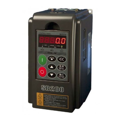
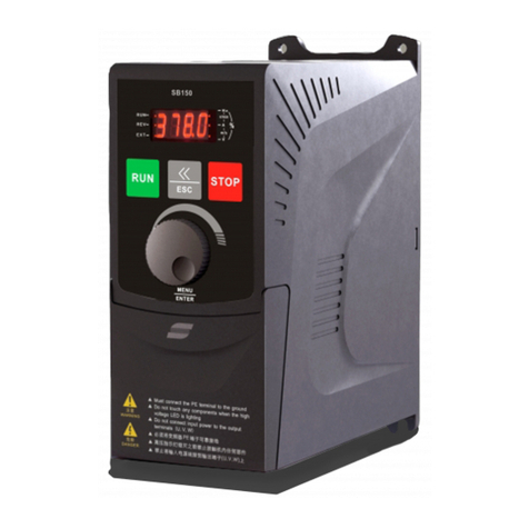
Senlan SB40S0.75-1.5 User manual

SENLAN INVERTE
R
Chengdu Hope SenLan Inverter Co., Ltd.
INSTRUCTION MANUAL
SB40 Series
General-purpose Inverter

- I -
Contents
1 General................................................................................. 1
1.1 Check upon delivery ......................................................... 1
1.2 Type description................................................................ 1
1.3 Nameplate ......................................................................... 2
1.4 Warranty............................................................................ 2
1.5 Precautions........................................................................ 3
2 Installation and Wiring ...................................................... 7
2.1 Installation ........................................................................ 7
2.2 Wiring of inverter ........................................................... 10
2.3 Wiring diagram ............................................................... 17
3 Use of Keypad Panel......................................................... 18
3.1 Appearance of keypad panel........................................... 18
3.2 Key definitions................................................................ 18
3.3 Fault code display ........................................................... 19
3.4 Frequency setting mode.................................................. 19
3.5 Display status of keypad panel ....................................... 19
3.6 Keypad panel operation .................................................. 20
4 Specifications..................................................................... 22
4.1 Standard specifications ................................................... 22
4.2 Common specifications .................................................. 23
4.3 External dimensions........................................................ 24

- II -
5 Function Table................................................................... 26
6 Function Details ................................................................ 34
7 Maintenance & Troubleshooting ..................................... 61
7.1 Daily inspection and maintenance .................................. 62
7.2 Periodical maintenance................................................... 62
7.3 Replacement of parts ...................................................... 63
7.4 Anti-interference measures ............................................. 64
7.5 Troubleshooting .............................................................. 65
8 Peripheral Devices ............................................................ 67
8.1 Connecting diagram of peripheral devices and options.. 67
8.2 Description of options..................................................... 68

SENLAN SB40 GENERAL
- 1 -
1 General
1.1 Check upon delivery
Check the following items after unpacking the inverter.
If the inverter has got any damages during the shipment.
If the inverter is exactly what you have ordered.
If all necessary accessories have been shipped along with the
inverter.
Contact our local sales agencies or distributors if you find anything
missing or when you have any troubles or questions regarding the
inverter.
1.2 Type description
Series code Phase Capacity Input voltage
SB40 S:3-phase
D: single phase 0.75~280KW None: 380V
D: 220V
SB40 S0.75

SENLAN SB40 GENERAL
- 2 -
1.3 Nameplate
1.4 Warranty
The warranty period of the product is 1 year from the purchase date.
However, the troubles caused by the following reasons are not
covered by this warranty even within the warranty period:
Failure caused by misoperation or by unauthorized repair or
modification;
Failure due to using the inverter beyond the specified operating
range;
Damage caused by the inverter falling or an accident during
shipping after the purchase.
Type:SB40S7.5
Input:380V 3~ 50/60Hz
Output:0-380V 3~ 0.1-400Hz
Rated Current:18A Rated Capacity:7.5KW
Serial Number:1234567
CHENGDU HOPE SENLAN INVERTER CO., LTD.
Made in China
SENLAN INVERTER
························································
························································

SENLAN SB40 GENERAL
- 3 -
1.5 Precautions
Read the following items before installing, wiring, operating and
maintaining the product, and always bear them in your mind.
Precautions in this manual fall into two types:
1.5.1 Installation
‧Install the inverter on a nonflammable object (such as metals).
Otherwise, there may be a risk of fire.
‧Do not install the inverter in an environment with explosive gas.
That may cause explosion.
‧Do not place any inflammable object near the inverter. That may
lead to fire.
‧Do not install or run the inverter when it is damaged or any
component is missing. That may lead to accident.
Danger
Danger :indicates that errors in operation may lead to
death or heavy injury to people or may destroy
the inverter.
Caution : indicates that errors in operation may lead to
medium or light injury to people or damage to
the inverter.

SENLAN SB40 GENERAL
- 4 -
‧ Install the inverter firmly on an object capable of bearing its weight.
Otherwise, the falling of the inverter may cause injury or damage.
‧ Do not drop metallic material in the inverter. That may lead to
accident.
1.5.2 Wiring
‧Connect a proper circuit breaker on the input side of the inverter to
protect the inverter from the faults of input wires.
‧The PE terminal of the inverter must be grounded securely.
Otherwise, electric shock or fire may occur.
‧The wiring must be done by a qualified electrician after the power is
cut off and the high-voltage indicator extinguishes.
‧Never connect the output terminals(U, V, W) to the input power.
That will destroy the inverter.
‧ The input power must conform to the specifications on the
nameplate. Otherwise, the inverter may be damaged.
Caution
Danger
Caution

SENLAN SB40 GENERAL
- 5 -
1.5.3 Operation
‧ Switch on the inverter power only after the wiring is completed and
the cover board is attached. Otherwise, electric shock may occur.
‧ Do not touch inverter terminals when electrical power is going to
the inverter even if the motor is stopped. That may lead to electric
shock.
‧ While charging an inverter that has long not been used, it must be
done by gradually increasing the input voltage to the rated value
through a voltage regulator. Otherwise, electric shock or explosion
may occur.
‧The running inverter can only be stopped by the panel STOP key or
external terminals. Directly cutting off the main power of the running
inverter is prohibited. That may damage the inverter.
‧Do not touch the braking resistor during the inverter running. That
may lead to electric shock or burn.
Danger
Caution

SENLAN SB40 GENERAL
- 6 -
1.5.4 Maintenance
‧ 10 minutes after power-off, measure the DC voltage between P and
N terminals with a multimeter. Only when this voltage drops below
36V, can the inverter be inspected and repaired. Otherwise, electric
shock or injury may occur.
‧ Only specially trained person can maintain the inverter. Otherwise,
electric shock or injury may occur.
‧ Do not leave any electricity conductors (such as metal) in the inverter
after repairing it. That may damage the inverter.
‧While charging an inverter that has long not been used, it must be
done by gradually increasing the input voltage to the rated value
through a voltage regulator. Otherwise, accident may occur.
1.5.5 Disposal
‧ When the product is no longer useful, dispose it as an industrial
waste. Otherwise, accident may occur.
Dan
g
er
Caution
Caution

SENLAN SB40 INSTALLATION AND WIRING
- 7 -
2 Installation and Wiring
2.1 Installation
2.1.1 Ambient temperature
-10℃~40℃, with humidity lower than 90%. If temperature>40℃,
the inverter must be derated by 5% for every addition of 1℃. At an
altitude above 1000m, the inverter must be derated by 3% for every
addition of 500m.
2.1.2 Installation location
The location for installing the inverter should meet the following
requirements:
Free from corrosive, inflammable and explosive gases and
liquids.
Free from dust, floating fibers and metallic particles.
The support is firm without vibration.
Free from direct sunlight.
Free from electromagnetic interference.
2.1.3 Installation space and heat dissipation
The inverter will generate heat during operating. To ensure good
ventilation, the inverter must be installed vertically and sufficient
space be kept around it, as shown below:

SENLAN SB40 INSTALLATION AND WIRING
- 8 -
When two or more inverters are installed in one cabinet, horizontal
arrangement is recommended to minimize the mutual thermal
influence. If vertical arrangement is necessary, a separating board
should be provided between them to prevent the heat of the lower
inverter affecting the upper one.
If the cabinet is equipped with exhaust fans at the top, the air flow
of the fans must be greater than the total outflow of individual
inverters. For those without exhaust fans, the top of the cabinet
should be left open if practicable; if not practicable, the area of the
air vent(inlet & outlet) at the top and bottom must be greater than
the total area of the up & down surfaces of individual inverters, and
the wind resistance at the air vent should be as small as possible.
If the inverter is installed on the wall of a control room, the room
not be enclosed and should have good ventilation。
Air
Inverter
120mm
or more
120mm
or more
50mm
or more
50mm
or more

SENLAN SB40 INSTALLATION AND WIRING
- 9 -
Multi-inverter installation methods are shown as the following
diagrams.
(a) Horizontal arrangement (b)Verticalarrangement
For the outflow and the surface(up & down) area of each SB40 type,
refer to the following table.
Type Outflow(m3/min) Surface area(m2)
0.75-3.7KW 1.5 0.023
5.5-7.5KW 3 0.033
11-15KW 4 0.051
18.5-22KW 7 0.065
30-55KW 10 0.092
75KW 14 0.13
90KW 14 0.15
110-132KW 28 0.17
160-220KW 28 0.22
220-280KW 42 0.24
Inverter
Air Air
Inlet
Outlet and cooling fa
n
Inverter
Air
Inverter
Outlet and cooling fan
Air inlet
Inverter
Separatin
g
board

SENLAN SB40 INSTALLATION AND WIRING
- 10 -
2.2 Wiring of inverter
2.2.1 Main circuit terminals
PE R S T P DB U V W
PE R S T P1 P+ DB U V W
PE R S T P1 P+ N U V W
N P+ P1 R S T PE U V W
PE P+ P1 N R S T U V W
18.5~22KW:
30KW:
37K
W
ove
r
:
0.75~7.5KW:
11~15KW:

SENLAN SB40 INSTALLATION AND WIRING
- 11 -
Description of main circuit terminals
Symbol Function
R, S, T Power supply terminals. For connecting 3-phase 380V
power.
U, V, W Inverter output terminals. For connecting a 3-phase motor.
P1, P+ Connect a DC reactor
P1, DB Connect an external braking resistor(0.75 ~ 7.5KW)
P+, DB Connect an external braking resistor(11 ~ 15KW)
P+, N Connect a braking unit
PE Inverter ground terminal
Main circuit power supply terminals [R, S, T]
① Connect the input power to these terminals via a circuit breaker.
The rated current of the breaker should be 1.5~2 times of that of
the inverter. There is no need to match the phase when
connecting.
② It is recommended that the input power be fed to the inverter via
an AC contactor to prevent further problems or damage to the
inverter in the event of a failure.
Inverter output terminals [U, V, W]
① Connect a 3-phase motor to these terminals in correct phase order.
If the run command does not match the rotary direction of the
motor, interchange any two of the U, V, W connections(the
counterclockwise rotation is defined as the forward direction
viewing from the load side).
② Do not connect a capacitor or a surge absorber to the output side

SENLAN SB40 INSTALLATION AND WIRING
- 12 -
of the inverter.
③ When the wiring length between the inverter and the motor are
long, the large inter-wire capacitance may result in abnormal
operation or even overcurrent trip. In this case, connect a filter or
a magnetic ring(s) to the output side of the inverter and
moderately decrease the carrier frequency. Refer to the following
table:
Wiring length <50m <100m ≥100m
Carrier frequency ≤9KHz ≤7KHz ≤3KHz
F79 ≤7 ≤5 ≤2
To suppress the interference generated on the inverter output side, it
is recommended to connect a dedicated filter to the output side, or
place the output power cables(U, V, W) into a metal conduit and
separated them with the control cables.
DC reactor terminals [P1, P+]
① These terminals are used to connect a power factor correcting DC
reactor, which should match the inverter capacity.
② These terminals are connected by a shorting-bar when shipped
from the factory, so remove this bar before connecting the DC
reactor.
③ The shorting-bar should not be removed if the DC reactor is not
used.
Caution

SENLAN SB40 INSTALLATION AND WIRING
- 13 -
External braking resistor terminals [P1, DB]/[P+, DB]
① These terminals are used to connect an external braking
resistor(option). See chapter 9 for specifications of the braking
resistor.
② When connecting the external braking resistor, use a twist pair
with its length less that 5 meters.
③ Never short P+ and DB. That will destroy the equipment.
Braking unit terminals [P+, N]
They are used to connect an external braking unit(option). See
Chapter 9 for specifications of the braking unit.
Inverter ground terminal [PE]
① To reduce noise and prevent electric shock and fire, this terminal
must be grounded securely and the grounding resistance should
be less than 10Ω.
②When connecting multiple inverters to the ground simultaneously,
be careful not to make the grounding wires form a closed circuit.
2.2.2 Control circuit terminals

SENLAN SB40 INSTALLATION AND WIRING
- 14 -
Description of control circuit terminals
Relay output terminals [30A, 30B, 30C]
These are programmable output terminals, can withstand
220VAC/1A.
Multi-function output terminals [Y1, Y2, Y3]
These are open collector output terminals, can withstand 24VDC
/50mA.
Multi-function input terminals [X1 ~ X5]
Refer to F69, Chapter 6.
Analog signal terminals [VRF, IRF, FMA, PO]
VRF: analog voltage input (DC 0~5V or 10V, input resistance
10KΩ).
IRF: analog current input(DC 4~20mA, input resistance 240Ω).
FMA: analog output(0~20mA, 0~10V). It can be output current, load
rate or frequency.
PO: pulse output.
Switch SW1 selects the FMA output between analog current and
voltage signal; SW2 selects VRF input between 0~5V and 0~10V;
SW3 selects VPF input between 0~5V and 0~10V.
External command terminals [JOG, FWD, REV]
JOG: when the inverter is in stop mode, short JOG and CM, then
short FWD(REV) and CM, the inverter will jog
forward(reverse).
FWD: it is valid when F02=1 or 2. Short FWD and CM, inverter will

SENLAN SB40 INSTALLATION AND WIRING
- 15 -
run forward. But if the operation is controlled by the keypad
panel, FWD is just for reverting the inverter direction, that is,
if short FWD and CM, inverter will run reverse, otherwise
forward.
REV: it is valid when F02=1 or 2. Short REV and CM, inverter will
run reverse; short REV, FWD and CM simultaneously, inverter
will stop.
External alarm terminal [THR] and reset terminal [RESET]
THR: open THR-CM, an external alarm signal(oLE) will be
generated and the inverter will immediately shut off the
output.
RESET: shorting RESET and CM will reset the inverter.
External power supply terminals [5V, GND, CM]
5V: control power supply, 5mA
GND: control power supply ground
CM: common terminal
FMA output selector [SW1] and VRF input selector [SW2]
SW1 selects the FMA output signal between analog voltage and
analog current. SW2 selects the VRF input signal between 0~10V and
0~5V analog voltage.
Attention:
Analog signals are easily disturbed by external interference. To
suppress the interference, use shielded cables as the control circuit
wires and firmly connect the shield cables to the common terminal or

SENLAN SB40 INSTALLATION AND WIRING
- 16 -
ground. Separate the control circuit wires from the main circuit wires,
power supply cables and other power lines, and run them across
instead of in parallel.
2.2.3 Wiring specifications
Inverter type Main circuit wiring
(mm²)
Control circuit wiring
(mm²)
SB40S0.75-1.5 2.5 ≥0.5
SB40S2.2-3.7 4 ≥0.5
SB40S5.5-7.5 6 ≥0.5
SB40S11-15 8 ≥0.5
SB40S18.5-22 16 0.5
SB40S30-37 25 0.5
SB40S45-55 35 0.5
SB40S75-90 60 0.5
SB40S110-132 90 0.5
SB40S160 120 0.5
SB40S200 180 0.5
SB40S220 210 0.5
SB40S280 240 0.5

SENLAN SB40 INSTALLATION AND WIRING
- 17 -
2.3 Wiring diagram
The wiring of the inverter consists of the main circuit wiring and the
control circuit wiring. External terminals can be used as required.
R
T
S
P+
N
DB
FMA
Y2
FWD
JOG
RESET
X1
X2
X3
CM
U
V
W
30A
30B
30C
Y1
P1 P+
SB40
INVERTER
3-phase
380V
Y3
PE
VRF
IRF
REV
THR
5V
Analog input
MCCB
DC reactor
Multi-function
output
Relay output
GND
M
FR
X4
X5
⊥
Analog output
Braking unit
This manual suits for next models
12
Table of contents
Other Senlan Inverter manuals
Popular Inverter manuals by other brands

Kramer
Kramer TOOLS 810B user manual

REFU
REFU 801 Series operating instructions

Generac Power Systems
Generac Power Systems 04679-1 Installation and owner's manual

SIP
SIP Medusa Ti-1002 manual

Link electronics
Link electronics Master Analog Generator SPG-812/SD Specification sheet

Chicago Electric
Chicago Electric 66967 Set up and operating instructions