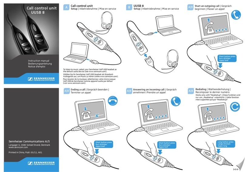
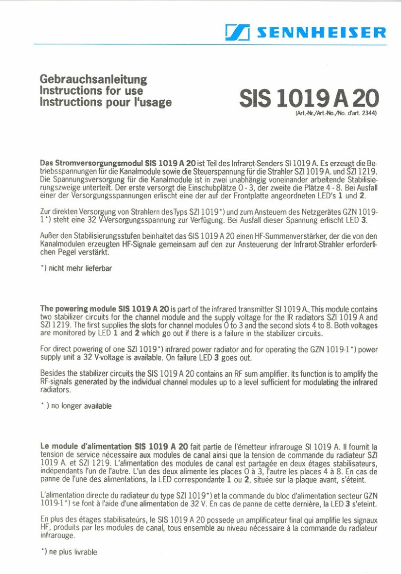
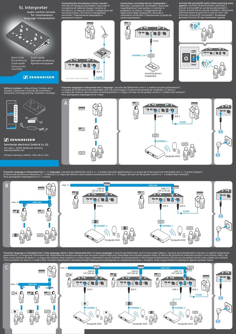
Sennheiser ADN CU1 User manual

Instruction manual
Control Unit
ADN CU1

ADN CU1 | 1
Contents
Contents
For your safety .................................................................................................................... 1
The ADN CU1 central unit ................................................................................................. 2
Package contents ............................................................................................................... 3
Components required for operation ............................................................................... 4
Product overview ADN CU1 central unit ........................................................................ 5
Structuring and controlling the conference system .................................................... 7
Structuring a wired conference system ..................................................................... 7
Setting up a wireless conference system ................................................................ 10
Configuring and controlling the conference system ............................................. 11
Input and output of audio signals ............................................................................ 11
Integration into a media control system ................................................................. 11
Preparing the ADN CU1 central unit for operation .................................................... 12
Setting up the central unit on a flat surface ........................................................... 12
Connecting the central unit to the mains power supply ...................................... 12
Setting up the conference system ................................................................................ 13
Setting up a small wired conference system with only the central unit ........... 14
Setting up a large wired conference system .......................................................... 15
Setting up a wireless conference system ................................................................ 16
Preparing to use the “Conference Manager” software ......................................... 17
Connecting external audio devices to the central unit ......................................... 18
Connecting a USB mass storage device for audio recordings
to the central unit ........................................................................................................ 18
Using the ADN CU1 central unit ..................................................................................... 18
Switching the conference system on/off ................................................................ 18
Deactivating the lock mode of the central unit ...................................................... 19
Functions of the keys .................................................................................................. 19
Setting the volume of the conference units’ built-in loudspeakers ................... 20
Configuring the conference system .............................................................................. 20
Working with the operating menu ........................................................................... 20
Overview of the operating menu .............................................................................. 22
Cleaning and maintaining the conference system .................................................... 27
Specifications ADN CU1 ................................................................................................... 28
For your safety
Please make sure to read the “Safety information” supplement included separately
with the product. This supplement contains important information on the safe
operation of the product as well as the manufacturer’s declaration and warranty
notes.
A detailed instruction manual for the overall ADN conference system can be found
• on the Internet at www.sennheiser.com or
• on the DVD-ROM supplied with the ADN CU1 central unit.
www
Manual

The ADN CU1 central unit
2 | ADN CU1
The ADN CU1 central unit
The ADN CU1 central unit is part of the Sennheiser ADN conference system.
The central unit controls the operation of the entire conference system. For wired
operation, up to max. 40 ADN D1 delegate units and ADN C1 chairperson units can
be directly connected to the central unit. For larger wired conference systems with
up to max. 400 conference units, the central unit can also manage up to 15 ADN PS
power supplies which in turn supply power the wired conference units. For wireless
conferencing, you can connect the ADN-W AM antenna module to the central unit
and operate up to 150 ADN-W C1 and ADN-W D1 wireless conference units.
For configuring the conference system, you can either use the central unit’s oper-
ating menu or the “Conference Manager” software. However, the full functionality
of a wireless conference system can only be configured using the “Conference Man-
ager” software. The software also allows you to control and monitor conferences
via a graphical interface.
Overview of a wired conference system
ADN C1 and ADN D1 wired conference units and ADN-W C1 and ADN-W D1
wireless conference units can be combined arbitrarily as long as you ensure
correct set-up and cabling and comply with the specifications (a conference
system can comprise a total of 400 conference units of which up to 150 can
be wireless).
ADN PS ADN PS
“Conference Manager”
software
ADN CU1
max. 40
ADN D1/ADN C1
max. 15 ADN PS
max. 400
ADN D1/ADN C1
per ADN PS with standard
cabling a max. of 70
ADN D1/ADN C1
per ADN PS with redundant
ring cabling a max. of 40
ADN D1/ADN C1
Conferences with up to a
max. of 40 participants Conferences with up to a max. of 400 participants

ADN CU1 | 3
Package contents
Overview of a wireless conference system
Package contents
1 ADN CU1 central unit
1 mains cable (with EU, UK or US mains plug, depending on version), length 1.8 m
1 instruction manual
1 “Safety information” supplement
1 DVD-ROM (including, among other things, the “Conference Manager” software,
the “ADN Cable Calculator” software and the instruction manual for the overall
conference system as PDF)
ADN-W AM
“Conference Manager“
software
ADN CU1
max. 150 ADN-W D1/ADN-W C1
Conferences with up to a max. of 150 participants
approx. 30 m

Components required for operation
4 | ADN CU1
Components required for operation
Central unit
Wired standard components
Power supplies
Conference units
System cables The system cables are black and have two shielded RJ45 plugs.
Wireless components
Antenna module
Wireless conference units
Number Description Cat. No. Function
1ADN CU1-EU central unit,
EU version
505553 Controls the conference
(wired and wireless
components) and
supplies power to a max. of
40 conference units and/or
one antenna module
ADN CU1-UK central unit,
UK version
505554
ADN CU1-US central unit,
US version
505555
Number Description Cat. No. Function
1 - 15
(optional)
ADN PS-EU power supply,
EU version
505546 Supplies power to conference
units connected in simple
strings or in redundant ring
topology,
for conferences with up to
400 conference units
ADN PS-UK power supply,
UK version
505547
ADN PS-US power supply,
US version
505548
Number Description Cat. No. Function
max. 400 ADN D1 delegate unit 502758 Allows to make contributions
to the conference
1 - 10
(optional)
ADN C1 chairperson unit 502759 Allows to manage the
conference
Number Description Cat. No. Function
Divers SDC CBL RJ45-2, 2 m 009842 Allows to interconnect
components and conference
units
SDC CBL RJ45-3, 3 m 009843
SDC CBL RJ45-5, 5 m 009844
SDC CBL RJ45-10, 10 m 009845
SDC CBL RJ45-20, 20 m 009846
SDC CBL RJ45-50, 50 m 009847
Number Description Cat. No. Function
1ADN-W AM antenna module 504743 Allows to transmit data via
RF
ADN-W AM-US antenna
module, US version
505715
Number Description Cat. No. Function
max. 150 ADN-W D1 wireless delegate
unit
504748 Allows to make contributions
to the conference
1 - 10
(optional)
ADN-W C1 wireless
chairperson unit
504745 Allows to manage the
conference
depending
on the
number of
wireless
conference
units
ADN-W BA battery pack 504744 Supplies power to wireless
conference units
ADN-W MIC 15-39 504750 Gooseneck microphones to
make contributions
ADN-W MIC 36-29 504751
ADN-W MIC 15-50 504752
ADN-W MIC 36-50 504753
Additional accessories for the ADN conference system can be found at
www.sennheiser.com.

ADN CU1 | 5
Product overview ADN CU1 central unit
Product overview ADN CU1 central unit
A Front view
On/off switch
Standard display key
Display panel
Jog dial
ESC key (Escape)
B Rear view
IN audio input
OUT audio output
PORT II socket (RJ45) for
connection of conference units/
ADN PS/ADN-W AM
PORT I socket (RJ45) for
connection of conference units/
ADN PS/ADN-W AM
VGA monitor output
USB socket (x2)
Network socket (RJ45)
Fans
Mains socket
Type plate
Hazard warnings
IN –– AUDIO –– OUT
PORT II PORT I
100-240V~
50/60Hz 240W
2x 52.8V 1.75A
ADN CU1
ESC
6 7 8 9 @ A B C
FE
D
12345
15
1
2
3
4
5
6
7
8
9
0
A
B
C
D
E
F

Product overview ADN CU1 central unit
6 | ADN CU1
Overview of the ADN CU1 display panel
After switch-on, the central unit’s display shows progress bars (for the booting
routine “Booting...” and the self test “Self-Test...”) and then the standard display:
For information on troubleshooting when error icons to are displayed, refer
to the ADN system manual.
Text/icon Possible display/function
Conference mode Current conference mode: “Direct Access”, “Override”,
“Push To Talk”, “Request”
Floor channel volume Current volume setting for the conference units’ built-
in loudspeakers
Number of
conference units
Number of conference units (wired or wireless)
connected to the conference system
Connection status icon Central unit is not connected to the “Conference
Manager” software and/or a media control unit.
Central unit is connected to the “Conference
Manager” software and/or a media control unit.
Structural change icon Icon appears when, since the last initialization, a
malfunction/change has occurred in the cabling
of the conference units.
Cable fault icon Icon appears when a conference unit is not
correctly connected to the ADN CU1 central unit.
Short-circuit icon Icon appears when there is a short circuit in the
cabling of the conference units. The display panel
lights up red.
Warning triangle Icon appears when there is a malfunction/
change. In case of malfunction, the display panel
lights up red.
Audio recording icon Icon appears when audio recording of the
conference is activated.
Icon flashes when storage space is low.
Icon appears when, after finishing the audio
recording, data is still written to the mass storage
device.
Icon appears when the audio recording failed. The
display panel lights up red.
Lock mode icon (see
page 19)
Lock mode of the central unit is deactivated.
Lock mode of the central unit is activated.
Direct Access
30 D1/C1
22
G
M
N
O
P
HI
LJ
K
G
H
I
J
K
L
M
N
O
P
K
N

ADN CU1 | 7
Structuring and controlling the conference system
Structuring and controlling the
conference system
Structuring a wired conference system
Basic requirements for a conference system comprising wired conference units
For safe operation of the conference system, make sure that all wired conference
units are supplied with a voltage of at least 35 V! The voltage supplied depends on
the number of connected conference units and on the cable lengths. The standard
cable length between the central unit or power supply and the first conference unit
is 50 m max. and the standard cable length between the individual conference
units is 2 to 5 m.
If these cable lengths are observed, safe operation of conference systems with the
following number of conference units is ensured:
• small conference systems comprising only an ADN CU1 central unit
– 30-40 conference units connected in simple strings
• large conference systems comprising an ADN CU1 central unit and a max. of
15 ADN PS power supplies
– max. 400 conference units connected in simple strings or in ring topology
per ADN PS power supply
– 60-70 conference units connected in simple strings
– 30-40 conference units connected in ring topology
If cable lengths are shorter, it might be that more conference units can be used.
ADN D1 delegate units and ADN C1 chairperson units can be combined in an arbi-
trary order. The number of chairperson units, however, is limited to 10 max. per
conference system. All wired components of the conference system are intercon-
nected using SDC CBL RJ-45 system cables.
Calculating the voltage supply of the conference units
The “ADN Cable Calculator” software allows you to calculate the voltage supply of
the wired conference units on the individual sections of a cable string or cable ring
and to plan the structure of the conference system. The software is included on the
DVD-ROM (supplied with the ADN CU1) or is available from your Sennheiser part-
ner or from the “Downloads” area on the product page at www.sennheiser.com.
For further information on the installation and use of the “ADN Cable Calculator”
software, refer to the help section of the “ADN Cable Calculator” software and to
the ADN system manual.

Structuring and controlling the conference system
8 | ADN CU1
Small conference system with simple cabling
For small conference systems with approx. 30-40 conference units, you require one
ADN CU1 central unit for controlling the conference. The conference units are inter-
connected in two cable strings which are directly connected to the central unit.
Large conference system with simple cabling
For setting up a large conference system with the maximum number of conference
units (i.e. up to 400), you require one ADN CU1 central unit for controlling the con-
ference and additional ADN PS power supplies for powering the conference units.
The conference units are interconnected in cable strings and up to four cable
strings can be connected to each ADN PS power supply.
PORT I
PORT II
ADN CU1
max. 50 m
approx. 2–5 m
52.8 V
>35 V
20
1 2 3
...
approx. 2–5 m
max. 40
ADN D1/ADN C1
ADN CU1
ADNCU1
ESC
ADNCU1
ESC
PORT I/II
PORT I 2
PORT I 1
PORT II 1
PORT II 2
ADN PS (max. 15)
ADN CU1
max. 50 m
approx. 2–5 m approx. 2–5 m
52.8 V >35 V
20
1 2 3
...
max. 50 m
ADN CU1 ADN PS
max. 70
ADN D1/ADN C1
ADNCU1
ESC
ADNCU1
ESC

ADN CU1 | 9
Structuring and controlling the conference system
Large conference system with redundant ring topology
The redundant ring topology ensures that, should one conference unit or system
cable fail or be manipulated, all other conference units of the cable ring will
continue to function reliably.
For setting up a large conference system with redundant ring topology, you require
one ADN CU1 central unit for controlling the conference and additional ADN PS
power supplies for powering the conference units. The conference units are inter-
connected in rings and two rings can be connected to each ADN PS power supply.
When connecting the conference units to an ADN PS power supply, you can
mix different cable topologies (simple cabling with cable strings or redun-
dant ring topology) as long as you ensure correct cabling and comply with
the specifications.
PORT I/II
ADN PS (max. 15)
ADN CU1
max. 50 m
approx. 2–5 m approx. 2–5 m
52.8 V >35 V
20
1 2 3
...
max. 50 m
ADN CU1 ADN PS
max. 40
ADN D1/ADN C1
PORT I 2
PORT I 1
PORT II 1
PORT II 2
ADNCU1
ESC
ADNCU1
ESC

Structuring and controlling the conference system
10 | ADN CU1
Setting up a wireless conference system
Basic requirements for a conference system comprising wireless conference units
The ADN-W C1 and ADN-W D1 wireless conference units connect wirelessly to the
ADN-W AM antenna module, which is connected to the ADN CU1 central unit via
system cable. The ADN-W AM antenna module can manage up to 150 wireless con-
ference units. The battery-powered wireless conference units are easy to use and
offer a high degree of flexibility. If the power supplied to the antenna module via
the system cable is not sufficient, you have to power the antenna module using the
NT 12-50C power supply.
Wireless conference system
For setting up a wireless conference system (up to wireless 150 conference units
can be used), you require one ADN CU1 central unit for controlling the conference
and one ADN-W AM antenna module for operating the wireless conference units
(range approx. 30 m).
ADN C1 and ADN D1 wired conference units and ADN-W C1 and ADN-W D1
wireless conference units can be combined arbitrarily as long as you ensure
correct set-up and cabling and comply with the specifications (a conference
system can comprise a total of 400 conference units of which up to 150 can
be wireless).
PORT I/II
ADN-W AM
ADN CU1
150
...
max. 50 m
ADN CU1 ADN-W AM
> 1 m > 0.5 m
> 0.5 m > 0.5 m
max. 150
ADN-W D1/ADN-W C1
ADNCU1
ESC
ADNCU1
ESC
approx. 30 m

ADN CU1 | 11
Structuring and controlling the conference system
Configuring and controlling the conference system
For configuring the conference system, you can either use the operating menu of
the central unit or the “Conference Manager” software. However, the full function-
ality of a wireless conference system can only be configured using the “Conference
Manager” software. The software also allows you to control and monitor confer-
ences via a graphical interface.
The “Conference Manager” software can be run in two different ways:
1. As a program on the central unit’s built-in PC
You have to connect a screen, keyboard, and mouse to the central unit (see
page 17).
2. As a program on a Windows PC
You have to install the “Conference Manager” software on the PC and integrate
the PC together with the central unit in a network (see page 17).
Input and output of audio signals
Via XLR sockets, you can feed audio signals to the floor channel or output the floor
channel.
For recording a conference on a USB mass storage device, you can use the recording
function of the ADN CU1 central unit, which saves the floor channel and all channels
of the conference units as audio files in wav format.
Integration into a media control system
The ADN conference system can be completely integrated into a media control sys-
tem. You can monitor and control all functions of the conference system via the
programmable commands of your media control system. For information on the
integration into a media control system, refer to the ADN system manual.
Conference Manager software
ADN CU1
1 2
For information on the installation and use of the “ADN Cable Calculator”
software, refer to the ADN system manual.

Preparing the ADN CU1 central unit for operation
12 | ADN CU1
Preparing the ADN CU1 central unit for
operation
Setting up the central unit on a flat surface
왘Make sure that the air vents are not covered or blocked.
왘Place the central unit on a flat surface as shown.
Connecting the central unit to the mains power supply
왘First connect the connector of the mains cable (supplied) to the mains
socket .
왘Connect the mains plug (EU, UK or US plug) of the mains cable to the mains
power supply.
The ADN CU1 central unit is now ready for operation.
For information on how to mount the central unit into a 19” rack, refer to
the ADN system manual.
CAUTION
Product damage due to unsuitable mains cables or power outlets!
An unsuitable power supply can damage the product.
왘Only use the mains cable (supplied) for connecting the product to the mains
power supply.
왘Only use multi-outlet power strips or extension cables with protective ground
contacts.
왘Only use mains cables with a 3-pin connector.
100-240V~
50/60Hz 240W
D
15
D

ADN CU1 | 13
Setting up the conference system
Setting up the conference system
Regardless of the number of conference units and the room size, we recommend
the following procedure for setting up the conference system:
왘Decide if you require wired or mobile wireless conference units. You can also
combine wired and wireless conference units.
왘Plan the number of conference units required for your conference system. A
total of 400 conference units (of which up to 150 can be wireless) can be used
in a conference system (the maximum number of ADN C1 or ADN-W C1 chair-
person units is limited to 10). Always take the largest possible number of par-
ticipants as a starting point.
If you are using wired conference units:
왘Plan if simple cabling is sufficient or if you require a redundant ring topology
(see page 7).
왘If necessary, calculate the number of ADN PS power supplies required (a maxi-
mum of 15 ADN PS power supplies can be used in a conference system).
왘If necessary, calculate the maximum length of the cabling in order to ensure
that all conference units connected are supplied with sufficient voltage (see
page 7).
왘Place the ADN CU1 central unit and, if necessary, the ADN PS power supplies
e.g. in the electrical equipment room or in the conference room.
왘Place the conference units at the corresponding seats.
왘Put out a sufficient number of SDC CBL RJ45 system cables in the required
lengths.
If you are using wireless conference units:
왘Place the ADN CU1 central unit e.g. in the electrical equipment room or in the
conference room. If possible, place the ADN-W AM antenna module directly in
the conference room. The transmission range of the antenna module is approx.
30 m.
왘Place the operational wireless conference units at the corresponding seats.
CAUTION
Product damage due to an unsuitable power supply!
If you connect standard network devices with RJ45 plugs (e.g. switches or network
cards) to the connection sockets PORT I , PORT II,DATA PS and /, the net-
work devices can be damaged due to an unsuitable power supply.
왘Only connect ADN C1 and ADN D1 conference units, ADN PS power supplies and
the ADN-W AM antenna module to the connection sockets PORT I , PORT II,DATA
PS and /.
When connecting the conference units to an ADN PS power supply, you can
mix different cable topologies (simple cabling or redundant ring topology)
as long as you ensure correct cabling and comply with the specifications.
In some countries/regions (e.g. Canada), the use of wireless components
operating in the 5.15 to 5.25 GHz frequency band (channel 5 to 8) is
restricted to indoor use.

Setting up the conference system
14 | ADN CU1
Setting up a small wired conference system with only
the central unit
For a small wired conference system, you do not require ADN PS power supplies.
Connecting conference units connected in a cable string to the ADN CU1
central unit
The following describes how to connect one cable string to the ADN CU1 central
unit. If necessary, repeat these steps for a second cable string.
왘Use a system cable to connect the PORT II socket or PORT I socket of the
ADN CU1 central unit to the IN socket of the first conference unit.
왘Use a system cable to connect the OUT socket of the first conference unit to
the IN socket of the second conference unit.
왘Repeat these steps for additional conference units.
왘If necessary, repeat all steps for a second cable string.
Please note that there is a limited number of approx. 15-20 conference
units per cable string due to the voltage drop on the cable string (see
page 7).
You can use optional cable holders for guiding the system cables. For
detailed information, refer to the ADN system manual.
8
9
<
A
<
IN OUT IN OUT IN OUT
PORT II PORT I
ADN CU1 ADN D1/ADN C1
PORT I
PORT II
IN OUT IN OUT IN OUT
IN OUT IN OUT IN OUT
ADN CU1
IN –– AUDIO –– OUT
PORT II PORT I
100-240V~
50/60Hz 240W
2x 52.8V 1.75A
8 9
IN
N
O
O
OU
UT
IN
N
O
O
OU
UT
IN
N
O
O
OU
UT
IN
N
O
O
OU
UT
IN
N
O
O
OU
UT
IN
N
O
O
OU
UT
201 2
...
201 2
...
<A

ADN CU1 | 15
Setting up the conference system
Setting up a large wired conference system
For conference systems comprising more than 40 conference units or when the
conference units are connected in a redundant ring topology, you require ADN PS
power supplies. A maximum of 15 ADN PS power supplies can be used in a confer-
ence system.
Connecting ADN PS power supplies to the ADN CU1 central unit
왘Use a system cable to connect the PORT II socket or PORT I socket of the
ADN CU1 central unit to the DATA CU/PS input socket of the first ADN PS
power supply (the maximum cable length allowed is 50 m).
왘Use a system cable to connect the DATA PS output socket of the first ADN PS
power supply to the DATA CU/PS input socket of the second ADN PS power
supply.
왘Repeat these steps for the remaining ADN PS power supplies.
왘Connect the conference units to the ADN PS power supply (refer to the instruc-
tion manual of the ADN PS power supply or to the ADN system manual).
8
9
<
A
<
CU/PS
PS
DATA
CU/PS
PS
DATA
CU/PS
PS
DATA
PORT II PORT I
ADN CU1
CU/PS PS
PORT I
12
PORT II
12
DATA
100 - 240V
50/60Hz 385W
PORTI & PORT II: max. 5.25A sum
ADN PS
IN –– AUDIO –– OUT
PORT II PORT I
100-240V~
50/60Hz 240W
2x 52.8V 1.75A
8 9 < A

Setting up the conference system
16 | ADN CU1
Setting up a wireless conference system
For operating the wireless conference units, you require one ADN-W AM antenna
module.
Connecting the ADN-W AM antenna module to the ADN CU1 central unit
왘Use a system cable (supplied with the ADN-W AM; the maximum cable length
allowed is 50 m) to connect the PORT II socket or PORT I socket of the
ADN CU1 central unit to the input socket of the ADN-W AM antenna
module.
If the power supplied to the antenna module via the system cable is not suf-
ficient, you have to power the antenna module using the NT 12-50C power
supply (detailed information can be found in the ADN system manual).
You can also connect the ADN-W AM antenna module to the PORT sockets
of an ADN PS power supply. It does not matter if you are using a string or
ring topology. The antenna module is connected just like a conference unit
to the cable string or cable ring.
8
9
4
PORT II PORT I
ADN CU1
IN –– AUDIO –– OUT
PORT II PORT I
100-240V~
50/60Hz 240W
2x 52.8V 1.75A
8 9
ADN-W AM
4
3

ADN CU1 | 17
Setting up the conference system
Preparing to use the “Conference Manager” software
Running the software installed on the central unit
To use the “Conference Manager” software installed on the central unit, you require
the following devices:
왘Use a Sub-D VGA cable to connect a screen to the VGA monitor output .
왘Connect the keyboard and the mouse to the two USB sockets .
왘Configure the screen, the keyboard and the mouse using the “Conference Man-
ager” software (for detailed information, refer to the ADN system manual).
Running the software on a separate Windows PC
To run the “Conference Manager” software on a separate Windows PC, the PC must
meet the following system requirements:
왘Use a network cable (Cat5) to connect the Ethernet socket of the central unit
to the network interface of your PC.
You can also connect the PC and the central unit using a switch or similar.
왘Install the “Conference Manager” software supplied on the DVD-ROM on your
connected PC and configure the network (for detailed information, refer to the
ADN system manual).
IN–– AUDIO –– OUT
PORTII PORTI
100-240V~
50/60Hz 240W
2x52.8V 1.75A
0
IN–– AUDIO –– OUT
PORTII PORTI
100-240V~
50/60Hz 240W
2x52.8V 1.75A
A
Device Requirements
Screen Connection: 15-pin Sub-D VGA
Resolution: 800 x 600 pixels or higher
1024 x 768 or 1280 x 1024 pixels recommended
Mouse Standard USB for Windows PCs
Keyboard Standard USB for Windows PCs
Supported language layouts: e.g. English, German, French,
Spanish, Italian, Dutch, Russian, Chinese, Japanese (for the
complete list, refer to the ADN system manual)
Use a USB hub if the number of USB sockets on the central unit is not
sufficient.
<
A
A
IN–– AUDIO –– OUT
PORTII PORTI
100-240V~
50/60Hz 240W
2x52.8V 1.75A
B
Component Requirement
Processor Intel Pentium 4 or AMD Athlon XP, 2 GHz or more
RAM Min. 1 GB, depending on your operating system
Hard disk Min. 500 MB free hard disk memory
Drives DVD-ROM
Interfaces/network Ethernet 100 MBit/s
TCP/IP internet protocol Internet Protocol version 4 (IPv4)
Screen Minimum resolution: 800 x 600 pixels
Recommended: 1024 x 768 pixels
Operating system Microsoft Windows XP Professional with SP3
Microsoft Windows Vista with SP2
Microsoft Windows 7
Microsoft Windows 8
B

Using the ADN CU1 central unit
18 | ADN CU1
Connecting external audio devices to the central unit
To output the floor channel via an external audio device:
왘Use an XLR cable to connect the OUT audio output of the central unit to an
external audio device.
To connect an external audio source and to feed its signals to the floor channel:
왘Use an XLR cable to connect the external audio source to the IN audio input
of the central unit.
Connecting a USB mass storage device for audio
recordings to the central unit
In order to be able to use the audio recording function of the ADN CU1 central unit,
you require a USB mass storage device with the following characteristics:
왘Connect the USB mass storage device to one of the two USB sockets .
왘If necessary, connect the mains unit of the USB mass storage device.
Using the ADN CU1 central unit
Switching the conference system on/off
Switching on a conference system comprising wired conference units
왘On the ADN CU1 central unit and, if connected, on the ADN PS power supplies,
set the on/off switch to position “I”.
The central unit switches on and its display panel lights up. If ADN PS power
supplies are connected, they are also switched on.
Switching on a conference system comprising an antenna module for
wireless operation
왘Set the on/off switch of the ADN CU1 central unit to position “I”.
The central unit switches on and its display panel lights up. The connected
ADN-W AM antenna module is also switched on.
IN –– AUDIO –– OUT
PORT II PORT I
2x 52.8V 1.75A
7
IN –– AUDIO –– OUT
PORT II PORT I
6
2x 52.8V 1.75A
7
6
USB mass storage device Requirements
Recommended memory
size
> 500 GB
File system NTFS, FAT32
Partition 1
Connection USB type A plug
Interface USB 2.0
Power supply via USB socket (approx. 500 mA) or separate
mains unit
IN ––AUDIO –– OUT
PORTII PORTI
100-240V~
50/60Hz 240W
2x 52.8V 1.75A
HDD
A
Use a USB hub if the number of USB sockets is not sufficient or if the USB
mass storage device is too large for connection to the central unit.
A
A
ADN CU1
ADN CU1
ESC
1
1
If you are using ADN PS power supplies in a conference system in which
wireless conference units are used, you have to switch on the ADN PS power
supplies as well (see previous section).
1
Other manuals for ADN CU1
3
Table of contents
Other Sennheiser Control Unit manuals
Popular Control Unit manuals by other brands

iDataLink
iDataLink maestro SW quick start guide
Harrington Signal
Harrington Signal Network Plus HS-3030 installation manual

Belden
Belden GRASS VALLEY AMX-1901 Guide to installation and operation
DFI
DFI AL968 user manual
Pilz
Pilz PNOZ mc6.1p operating manual
Honeywell
Honeywell NOTIFIER ASY-01-044-NIM Product installation sheet

