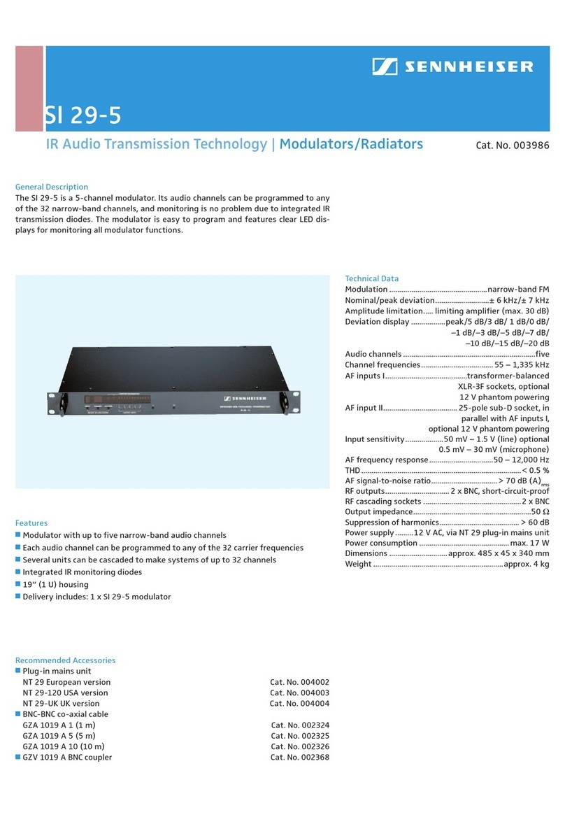
Sennheiser SZI 1012 User manual


1-
INFRAROT -LEISTU NGSSTRAH LER
SZI1012
Einleitung
Der Infrarot-Leistungsstrahler SZI1 012 wandelt das von den
Steuersendern SI1 011, SI1 012 oder SI1 019 kommende elek-
trische Signal in moduliertes Infrarotlicht um. Vom eingebauten
Netzteil des Steuersenders können ac ht SZI1 012 direkt ge-
speist werden. Die Zahl der angeschlossenen Strahler kann
beliebig erhöht werden. Die entsprechende Stromversorgung
GZN 1019 muß dann von weiteren separaten Netzteilen kommen.
Beschreibung
Die Frontseite enthält 12lnfrarot-Sendedioden und eine Leucht-
diode (LED) als Funktionsanzeige. Fest mit dem Gehäuse ver-
bunden ist eine 3 m lange Anschlußleitung mit 5poligem Stecker,
über die die HF-Ansteuerung und die Betriebsspannungs-
versorgung erfolgt.
Die Eingangsstufe arbeitet als Begrenzerverstärker, der die
optimale Amplitude für die Aussteuerung der eingebauten End-
stufe gewährleistet - unabhängig vom Ausgangspegel des
Steuersenders. In der Endstufe wird eine Infrarotdiode zur
optischen Gegenkopplung verwendet, die dadurch für eine
Linearisierung des abgestrahlten Signals sorgt. Fällt die Endstufe
aus, so schaltet sich der SZI 1012 automatisch ab. Die rote
Funktionskontrolle erlischt.
Die von außen zugeführte Versorgungsspannung soll zwischen
29 und 34 V liegen.
Montage
Bei der Montage des Leistungsstrahlers sollten Sie stets be-
denken, daß das unsichtbare Infrarotlicht ohne Abschattung die
Empfangslinse des Empfängers erreichen soll. Eine direkte
Sichtverbindung zwischen Strahlern und Empfängern ist die
beste Lösung. Reflexionen sind an zweiter Stelle als Empfangs-
möglichkeit zu nennen. Eine recht hohe Montage mit leichter
Neigung nach unten in den Raum hat sich in der Praxis als günstig
erwiesen. Der 3;g"-Gewindeanschluß erlaubt viele Anschluß-
möglichkeiten. Flexibilität im Aufbau ist durch den 3;g"-Gewinde-
anschluß gegeben. Für den transportablen Einsatz empfehlen
wir die Tischklemmvorrichtung MZT 237 oder das Stativ
MZS 142. Zwei Strahler können mit Hilfe der Traverse MZS 235
montiert werden.
Die Verbindung der Leistungsstrahler mit dem Sender erfolgt
über eine flexible Steuerleitung. Diese Steuerleitung überträgt
die HF-Signale zu den Leistungsstrahlern und schaltet zugleich
eventuell angeschlossene Netzgeräte. Für Festinstallationen
kann das Spezialkabel 12-1036 als Meterware von uns bezogen
werden.
- -- ---
Der Strahler sollte vorzugsweise in Verbindung mit dem Zwei-
kanal-Steuersender SI1 012 verwendet werden. Zur Ermittlung
der erforderlichen Anzahl von Leistungsstrahlern gilt dann
folgende Faustformel: für 2 m2Grundfläche eine Diode, d. h. mit
einem Leistungsstrahler können bei Stereo-Betrieb maximal
24 m2ausgeleuchtet werden.
EIngangspegel
Frequenzbereich
EingangsImpedanz
Wellenlänge des abgestrahlten Infrarotlichts
Strahl ungsleistu ng
Unterdruckung der Oberschwingungen
bzw. der Intermodulationstrequenzen
Setrrebsspannung
Stromaufnahme
Setrrebskontrolle
Gehäuseabmessungen In 10m
Länge des Anschlußkabels
Anschlußstecker
20 mV 700 mV
40 kHz 400 kHz
ca.4 kQ
950 nm
ca. 100 mW
i'; 35 dS
29 34 V
ca. 145 mA
durch Rotlichtdiode
200 x 80 x 23
3m
Tuchel Nr. T 3360-002 oder
Sinderstecker Nr. 09-0013-00-05
1~ HF, 2 ~ Schrrm
3 ~ - US, 5 ~ +Us
ca 450 9
Anderungen, vor allem zum technischen Fortschritt, vorbehalten

INFRAREDPOWERRADIATOR
SZI1012
Introduction
The infrared power radiator 8Z11 012 in connection with the
infrared transmitters 811011, 811012 or 811019 serves to cover
large areas. The built-in power supply of the infrared transmitter
is able to feed ei 9 ht 8Z11 012 directly. The number of the
connected power radiators can be increased without limit. Inthis
case additional power supplies (e. g. GZN 1019) are necessary.
Description
The front panel contains 12 infrared transmitting diodes and one
LEO as function indicator. A connection cable with a length of 3 m
and a 5-pin connector ist firmly connected to the housing. This
cable carrys the modulated signals to the radiator and also the
OC-current.
The input stage works as limiter amplifier giving the guarantee of
an optimal amplitude for the built-in output stage - independent
of the output level of the infrared transmitter. The output stage is
equipped with one infrared diode for optical feedback, ensuring
linearity of the transmitted infrared signal. If the output stage is
defect the 8Z11 012 automatically switches off, together with the
red LEO function indicator.
The external supply voltage must be between 29 and 34 V.
Mounting
When positioning the power radiator please always keep in mind
that the invisible infrared light must reach the lens of the receiver
without shadowing. A direct optical connection between radiator
and receiver is the best solution. Infrared transmission by
reflections isalsopossiblewith certain limitations. High positioning
with a slight tilt downwards has been found advantageous in
practice.
Mounting flexibility is given by means of a3;g" internal thread. For
portable use we recommend the table clamp MZT 237 or the floor
stand MZ8 142. Two power radiators can be adapted by using
the twin-bar MZ8 235.
The power radiator is connected to the transmitter by means of a
flexible control cable. This cable transmits the RF-signals to the
power radiators and switches on at the same time the eventually
connected power supplies GZN 1019. For fixed installations
this special cable (no. 12-1036) can be ordered per meter from
8ennheiser.
The radiator should preferably be used in connection with the two
channel transmitter 811012. The following rule of thumb is valid
to determine the number of power radiators required: For an area
of 2 m2one diode is necessary, that means one power radiator
covers up to 24 m2at stereo operation.
'" - --- ~ - ~ -~ - -
Technical Data
~ ~ -- ~- -- -= ~~
\I
,20mV,700mV
. 40 kHz . . . 400 kHz
appx.4 kQ
950 nm
appx. 100mW
:;;35dB
29. 34 V
. appx. 145mA
. by LED(red)
200 x 80 x 23
3m
. Tuchel no.T 3360-002 or
Binder no. 09-0013-00-05
1 = RF.2 = sereen
3 = - DC.5 = + DC
appx.450 9
Inpullevel ..
Frequeneyrange
Inpulimpedanee .
WavelengthofradlatedInfraredlight
Radiatedpower. .. .
Suppressionof harmoniesresp.
intermodulation
DC-supply voltage.
Currenteonsumption
IFunetionindieator .. ..
Housingdimensions in mm .
,Lengthofeonneetioneable
Conneetor
Weight
We reserve fhe right to aiter speeifleations.in partieularwlth regard to teehnical
improvements
!
J

RAOIATEUROEPUISSANCE
INFRAROUGESZI1012
Introduction
Le radiateur de puissance infrarouge SZI1 012 sert, en combi-
naison avec les emetteurs pilote SI1 011, SI 1012 ou SI1 019,
Ei.I'eclairage infrarouge de salles Ei.grandes dimensions. L'alimen-
tation incorporee Ei.I'emetteur pilote peut alimenter directement
huit SZI1 012. Le nombre des radiateurs branches peut iHre
agrandi Ei.volonte. L'alimentation adequate GZN 1019 doit alors
iHregarantie par des alimentations supplementaires externes.
Description
La plaque frontale contient 12 diodes d'emission infrarouges et
une diode luminescente (LED) qui sert d'indicateur de fonction.
Un cable de raccordement de 3 m avec fiche pentapolaire, monte
Ei.demeure au boitier, vehicule le signal HF d'attaque et la tension
d'alimentation.
L'etage d'entree travaille comme amplificateur limiteur, qui
garantit une amplitude optimale pour lamodulation de I'etage final
incorpore, independamment du niveau de sortie de I'emetteur
pilote. Dans I'etage final, une diode infrarouge sert Ei.la contre-
reaction optique, afin de proceder Ei.une linearisation du signal
emis. Si I'etage final est defaillant, il se met automatiquement hors
circuit. La diode rouge de controle s'eteint.
Latension d'alimentation venant de I'exterieur doit se situer entre
29 et 34 V.
Montage
En procedant Ei.I'installation du radiateur a puissance il faut
toujours se rendre compte du fait que la lumiere infrarouge
invisible doittoujours arriver a lalentille de reception du recepteur
sans voir d'objet opaque sur son chemin. Une vue directe entre
radiateurs et recepteurs se trouve iHre la meilleure solution.
Comme seconde possibilite de reception il faut citer les
reflexions. Pour la pratique, une installation relativement elevee
et legerement inclinee vers le bas de I'espace s'est montree
favorable.
Laflexibilite de I'installation est donnee par le filetage 3/8", Pour
un usage mobile, nous recommandons la pince de fixation a
serrage MZT 237 ou le pied de micro MZS 142. Deux radiateurs
peuvent iHre montes a I'aide de la reglette MZS 235.
La communication des radiateurs de puissance Ei.I'emetteur se
fait a I'aide d'un cable pilote flexible. Ce cable pilote transmet les
signaux HF vers les radiateurs de puissance et effectue en meme
temps la commutation des alimentations eventuellement
raccordees. Pour des installations fixes, ce cable special
(no. 12-1036) peut etre commande par metres chez Sennheiser
electronic.
IIest conseille d'utiliser le radiateur de preference en relation avec
I'emetteur pilote a deux canaux SI1 012. Pour trouver le nombre
requis de radiateurs de puissance on peut utiliser la formule
suivante: Une diode pour une surface de 2 m2c. a. d. un radiateur
de puissance peut eclairer en regime stereo une surface de
24 m2au maximum,
Niveaud'entree
Bande passante
Impedance d'entree
Langueur d'onde de la lumlere infrarouge emlse
PUlssance d'emlsslon
Attenuatlon des harmonlques resp
Intermodulation
Tension d'allmentation
Consommatlan de courant
Contröle des fonctlans
Dimensions du baHier en mm
Longueur du cable de raccardement
Connecteur
20 mV 700 mV
40 kHz 400 kHz
env, 4 kQ
950 nm
env, 100 mW
~ 35 dB
29 34 V
env, 145mA
par dlade LED rouge
200 x 80 x 23
3m
Tuchel No, T 3360-002 ou
fiche Binder No, 09-0013-00-05
1~ HF, 2 ~ bllndage
3 ~ - UB, 5 ~ + UB
env, 450 g
Palds
Modlficatlons, surtaut dans l'lnteret du progres technique, reservees,

Table of contents
Languages:
Other Sennheiser Modulator manuals

Sennheiser
Sennheiser SI 120R Dimensions

Sennheiser
Sennheiser SI 30 User manual

Sennheiser
Sennheiser SI 30 User manual

Sennheiser
Sennheiser SI 1015 User manual

Sennheiser
Sennheiser SI 30 Dimensions
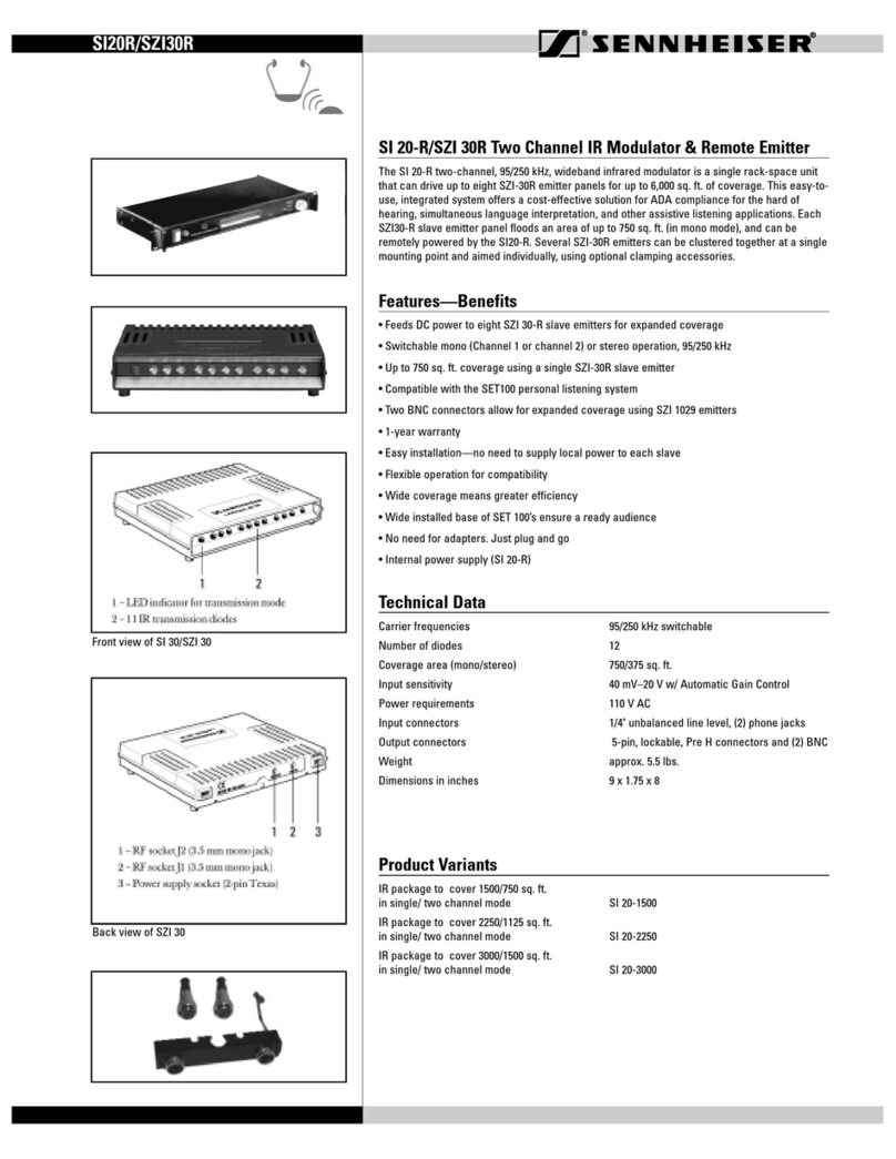
Sennheiser
Sennheiser SI 20 Dimensions
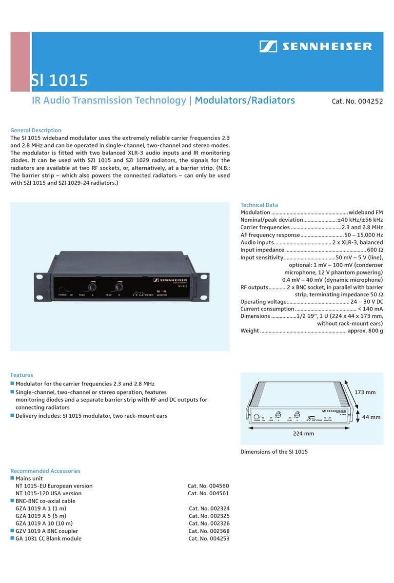
Sennheiser
Sennheiser SI 1015 Dimensions

Sennheiser
Sennheiser SZI 1015 User manual
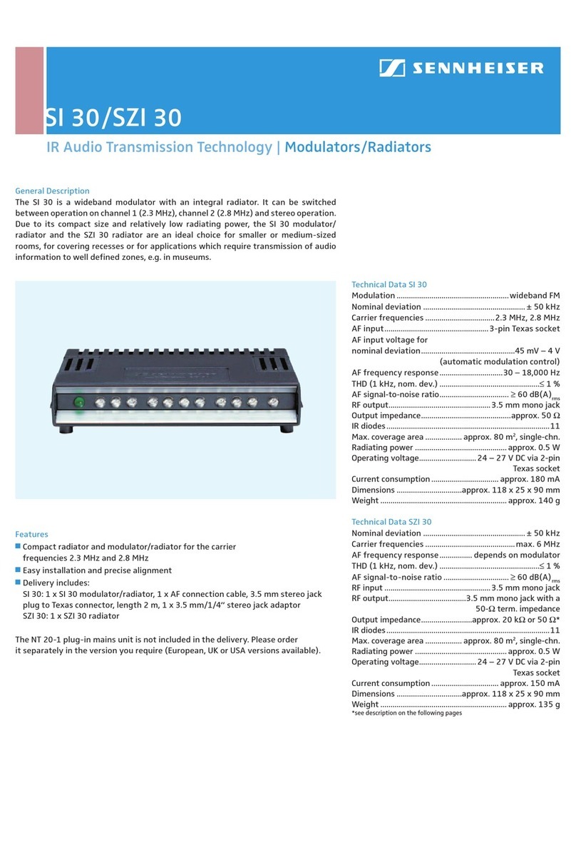
Sennheiser
Sennheiser SZI 30 Operating and maintenance instructions

Sennheiser
Sennheiser SI 30 User manual
