Sennheiser SZI 1015 User manual

1
SI1015
SZI1015
BEDIENUNGSANLEITUNG
INSTRUCTIONS FOR USE
NOTICE D‘EMPLOI
ISTRUZIONI PER L‘USO
INSTRUCCIONES PARA EL USO
GEBRUIKSAANWIJZING

32
SI1015
SZI1015
BEDIENUNGSANLEITUNG
BEDIENUNGSANLEITUNG ..................................................................................................................................3
INSTRUCTIONS FOR USE ..................................................................................................................................11
NOTICE D‘EMPLOI ..............................................................................................................................................19
ISTRUZIONI PER L‘USO .....................................................................................................................................27
INSTRUCCIONES PARA EL USO.......................................................................................................................35
GEBRUIKSAANWIJZING...................................................................................................................................43

5
4
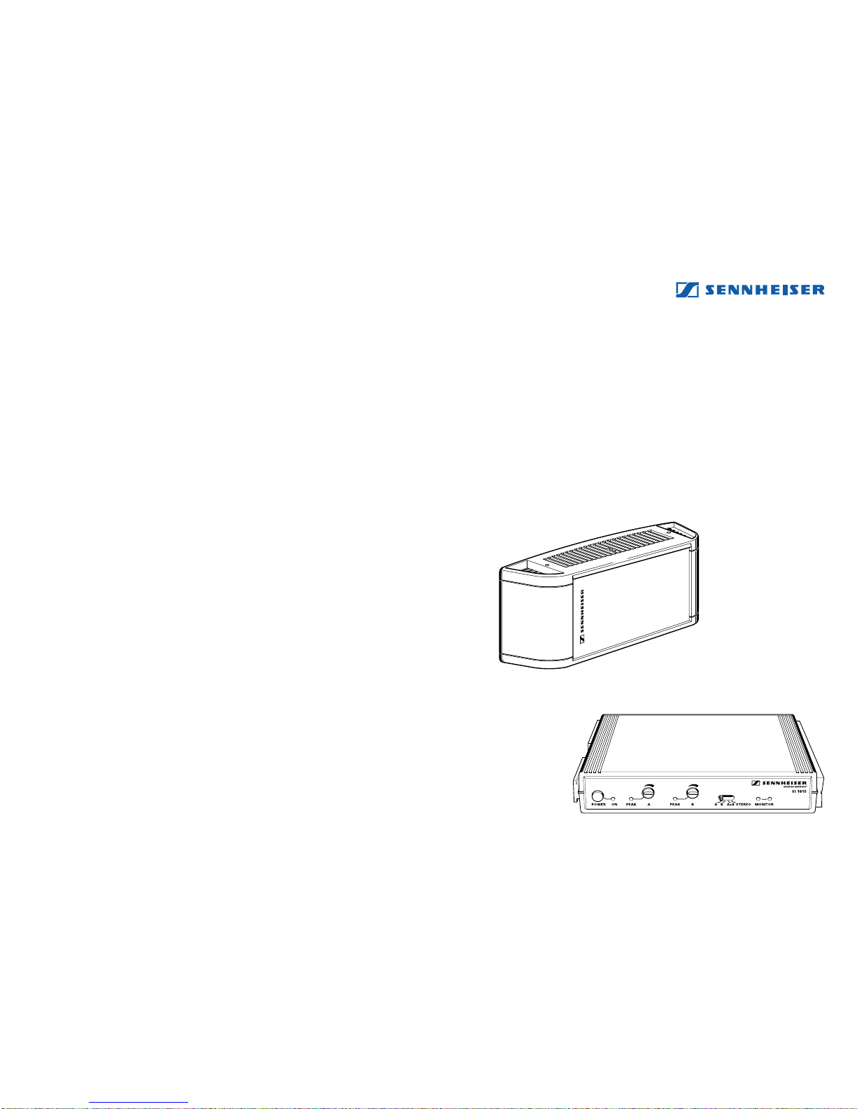
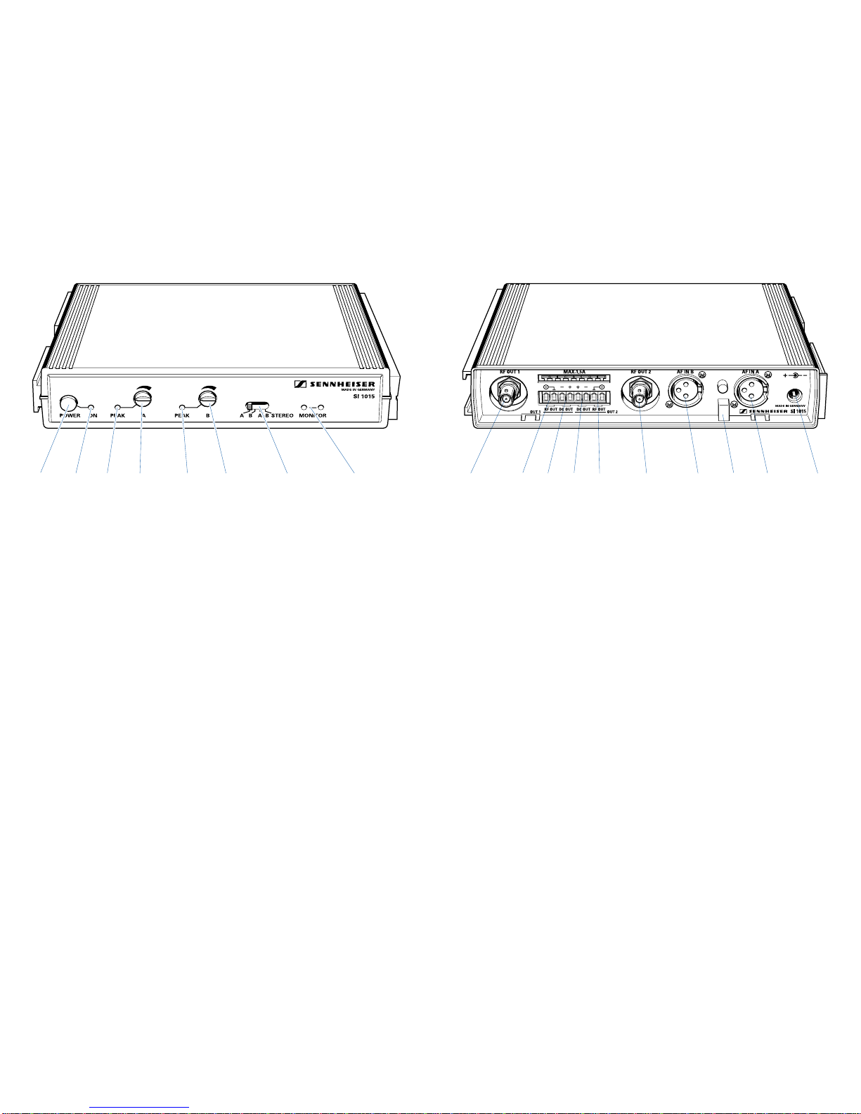
Anschluß- und Bedienelemente SI 1015 (Frontseite)
Ein- / Aus-Schalter
Netzkontroll-LED
Übersteuerungsanzeige Kanal A
Pegelsteller Kanal A
Übersteuerungsanzeige Kanal B
Pegelsteller Kanal B
Wahlschalter: Kanal A
Kanal B
Kanal A/B, 2 x mono
Kanal A und B als Stereo-Signal
IR-Sendedioden (zur direkten Kontrolle durch einen IR-Empfänger)
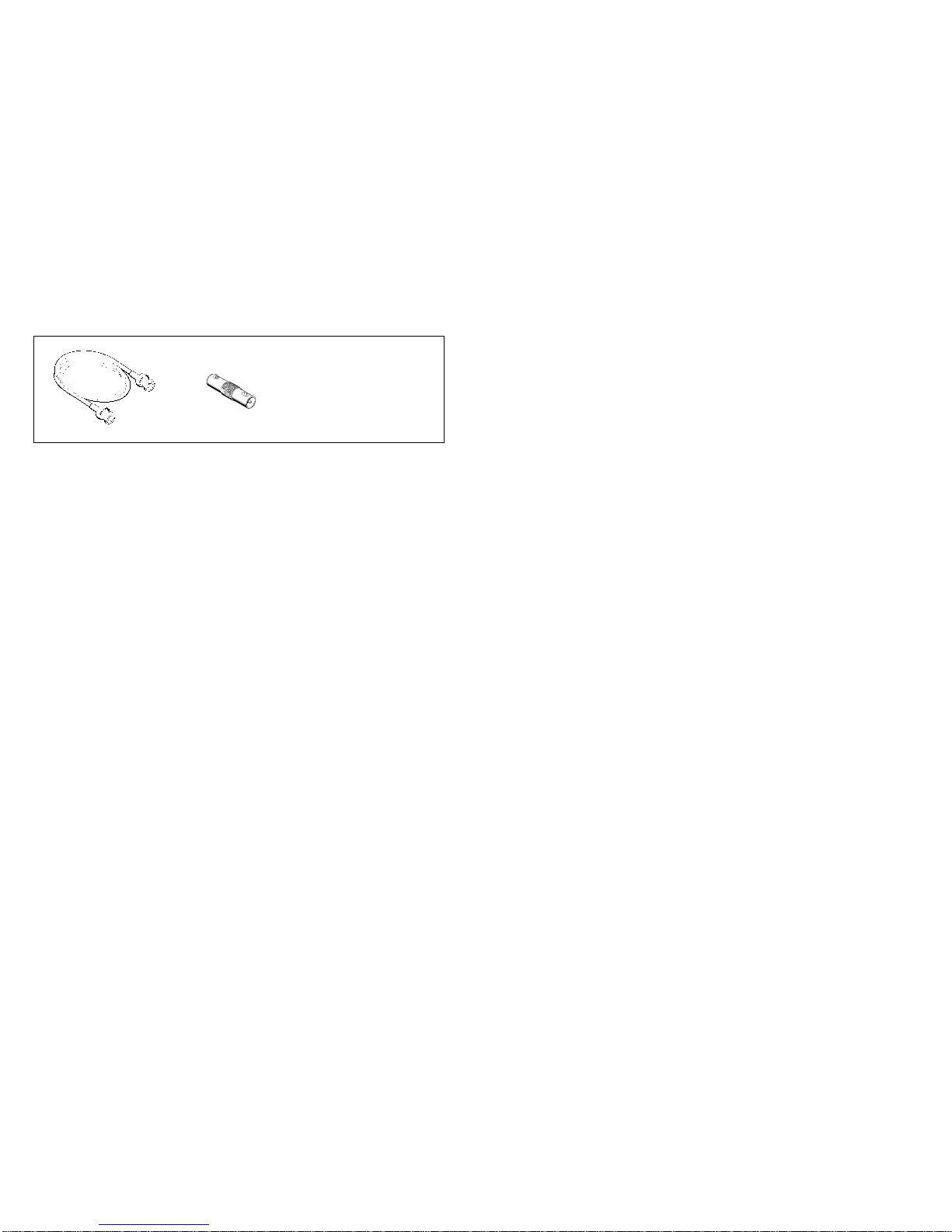
Anschluß- und Bedienelemente SI 1015 (Rückseite)
HF-Ausgangsbuchse 1, Anschluß für Leistungsstrahler
HF-Klemmanschluß 1, Anschluß für Leistungsstrahler (parallel zu )
Anschluß 1 Stromversorgung Leistungsstrahler (durchgeschleift von )
Anschluß 2 Stromversorgung Leistungsstrahler (durchgeschleift von )
HF-Klemmanschluß 2, Anschluß für Leistungsstrahler (parallel zu )
HF-Ausgangsbuchse 2, Anschluß für Leistungsstrahler (gleiches Signal wie )
NF-Eingang B
Zugentlastung
NF-Eingang A
Anschluß Stromversorgung 25 - 35 V DC über Netzteil
(Netzteil NT 1015-EU oder NT 1015-120) oder aus einer anderen Gleichstromquelle.

76
Anschluß- und Bedienelemente SZI 1015
HF-Eingang (BNC-Buchse)
Umschalter Mono- / Multichannelbetrieb
HF-Ausgang (BNC-Buchse)
Gewinde für Stativbefestigung
HF-Klemmanschluß, Eingang (parallel zu )
Klemmanschluß Stromversorgung aus Sender SI 1015 oder
über Netzteil 25 - 35 V (Netzteil NT 1015-EU oder NT 1015-120)
Klemmanschluß Stromversorgung (durchschleifen zum zweiten Strahler SZI 1015)
HF-Klemmanschluß, Ausgang (parallel zu )
1 Zugentlastung
Schließen Sie das Kabel vom Netzteil an der Buchse des Steuersenders SI 1015 an und führen
Sie es durch die Zugentlastung. Der Stecker kann so nicht mehr aus der Buchse herausrutschen
und den Betrieb unterbrechen.
Hinweis
Eine Zugentlastung ist besonders dann wichtig, wenn das Gerät fest in einem
Rack eingebaut ist. Im Inneren eines Racks liegen oft sehr viele Leitungen - eine
solche Halterung verhindert, daß sich die Leitungen gegenseitig herausdrücken.
2 Anschluß der Infrarot-Leistungsstrahler SZI 1015
An den Buchsen und des Steuersenders SI 1015 können Sie zwei Leistungsstrahler
SZI 1015 anschließen. Dazu verwenden Sie fertig konfektionierte Koaxial-Kabel mit BNC-
Steckern.
Sie können auch Koaxial-Kabel ohne Stecker verwenden, die in der Klemmleiste an den
Klemmen und befestigt werden. Entfernen Sie dazu am Kabel etwa 20 mm der
Kunststoffummantelung und drehen Sie das Geflecht zusammen. Der Mittelleiter muß ca.
10 mm abisoliert werden. Das Geflecht wird an der Masseklemme eingesteckt, der Innen-
leiter außen daneben.
Der letzte Strahler eines Zweiges wird mit einem 50ΩAbschlußwiderstand versehen, Da-
mit werden stehende Wellen in der HF-Leitung vermieden.
3 Durchschleifen der Stromversorgung zu den Leistungsstrahlern.
Bis zu zwei Leistungsstrahler SZI 1015 oder ein SZI 1029-24 können über den Steuersender
SI 1015 ausdem Netzteil NT1015 mit25-29 V gespeist werden. Dazu steht die Stromversor-
gungan den beidenKlemmenpaarenbzw. zurVerfügung.Verbinden Sie dieLeistungs-
strahler mit diesen Klemmen über ein zweiadriges Kabel mit je 1,5 mm2Querschnitt.

98
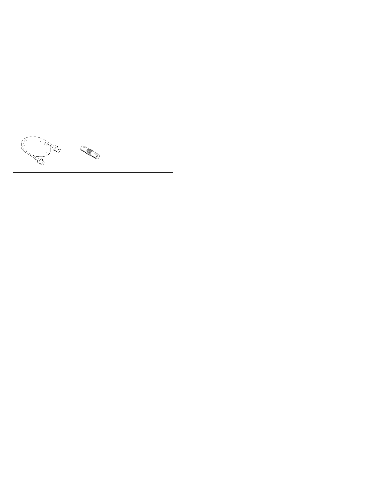
Elektrisches Zubehör
Anschlußkabel GZL 1019 A1
Für den Anschluß des Strahlers an die Sender SI 1015, SI 29-5 oder SI 1029. Länge 1 m.
Anschlußkabel GZL 1019 A5
Für den Anschluß des Strahlers an die Sender SI 1015, SI 29-5 oder SI 1029. Länge 5 m.
Anschlußkabe GZL 1019 A10
Für den Anschluß des Strahlers an die Sender SI 1015, SI 29-5 oder SI 1029. Länge 10 m.
BNC-Doppelbuchse GZV 1019
Zum Zusammenschalten von zwei Anschlußleitungen GZL 1019 A1, -5, -10.
Fürden NF-Anschluß verwendenSie bittehandelsübliche XLR-3-Anschlußkabel in der gewünsch-
ten Länge.
Hinweis: Sennheiser-Druckschrift„Infrarot-Planungsbroschüre“
Über die verschiedenen Einsatzmöglichkeiten der Sennheiser-Infrarot-Systeme informiert Sie die
Sennheiser-Druckschrift„Infrarot-Planungsbroschüre“.NebenweiterreichendenInformationenüber
die Technik der Infrarot-Tonübertragung finden Sie dort auch Anwendungsbeispiele und Kombi-
nationen mit Übersichtslisten für Ihre Planung.
Im Rahmen der Produktpflege kann es vorkommen, daß nach Redaktionsschluß dieser Druck-
schrift technische Änderungen der beschriebenen Produkte vorgenommen werden. Wir bitten um
Ihr Verständnis.
Technische Daten
SZI 1015 Leistungsstrahler
Anzahl der Sendedioden 66
Mittlere Strahlungsleistung 2 W
Wellenlänge des abgestrahlten Infrarotlichts ca. 880 nm
Trägerfrequenzbereich 30 kHz bis 6 MHz
HF - Eingang 50 mV – 5 V / ca. 5 kΩ
Eingang / Ausgang BNC - Buchsen / Klemmleisten
Schaltschwelle für Einschaltautomatik 50 mV
Betriebsspannung 25–35 V DC (z.B. aus Netzteil NT 1015)
oder aus Steuersender SI 1015
Stromaufnahme 0,75 A bei 25 V
Standby-Betrieb max. 60 mA
Abmessungen in mm ca. 250 x 100 x 80
Gewicht ca. 1,3 kg
SI 1015 Steuersender
Betriebsspannung 25 - 35 V DC (z.B. aus NT 1015)
Stromaufnahme < 140 mA
Abschluß-Impedanz der HF-Ausgänge 50 Ω
Trägerfrequenz 1 2,3 MHz
Trägerfrequenz 2 2,8 MHz
Eingänge 2 x Audio XLR-3 symmetrisch,
Eingangsempfindlichkeit 50 mV bis 10 V
HF-Ausgänge 2 x BNC, parallel zur Klemmleiste
NT 1015 Netzteil
Netzspannung geregelt 100 - 240 Volt AC
Ausgangsspannung 29 V DC
Ausgangsstrom 1,7 A, ausreichend für einen Steuersender
SI 1015 und zwei Leistungsstrahler SZI 1015
oder einen Steuersender SI 1015 und einen
Hochleistungsstrahler SZI 1029-24
1110
SI1015
SZI1015
INSTRUCTIONS FOR USE

13
12
Connections and operating elements of the SI 1015 (front panel)
ON/OFF switch
LED power indicator
Overmodulation indicator channel A
Level control channel A
Overmodulation indicator channel B
Level control channel B
Channel selector switch: channel A
channel B
channel A/B, 2 x mono
channel A and B, stereo
IR transmitting diodes (for direct monitoring via an IR receiver)
Connections and operating elements of the SI 1015 (back panel)
RF output socket 1 for connecting a radiator
Barrier strip RF contacts 1 for connecting a radiator
(alternative connection to , wired in parallel)
Barrier strip DC outputs for radiator 1
Barrier strip DC outputs for radiator 2
Barrier strip RF contacts 2 for connecting a radiator
(alternative connection to , wired in parallel)
RF output socket 2 for connecting a radiator (same signal as )
AF input B
Cable grip
AF input A
Input socket for plug-in mains unit – power supply, 25 - 35 V DC via NT 1015
plug-in mains unit or via a different DC source.

1514
Connections and operating elements of the SZI 1015
RF input (BNC socket)
Mono/multi switch
RF output (BNC socket)
Thread for mounting the radiator
Barrier strip RF contacts, input (wired in parallel with )
Barrier strip DC inputs – for powering from the SI 1015 modulator
or via the NT 1015 plug-in mains unit
Barrier strip DC outputs (for daisy-chaining a second SZI 1015)
Barrier strip RF contacts, output (wired in parallel with )
1 Cable grip
Insert the connector of the plug-in mains unit into socket on the SI 1015 modulator and pass
the cable through the cable grip as shown. Because of the cable grip, the connector cannot slip
out of the socket and interrupt operation.
Note
Acable grip isparticularly importantwhen thedevice ispermanently rackmounted.
Inside the rack there are often a large number of cables – a cable grip prevents the
cables from pulling each other out.
2 Rack mounting
The SI 1015 can be rack mounted into 1 U of a 19” rack by using accessories GA 1031-AM or
GA 1031-CC. The GA 1031-CC is a blank module to bring the SI 1015 to full 19” width, the
GA 1031-AM is identical but has additional BNC sockets to bring outputs and to the front
panel. The rack mountings are supplied with the SI 1015.
3 Connecting the SZI 1015 radiators
Sockets andon the SI 1015 modulator can be used to connect two SZI 1015 power radiators.
For connecting the radiators, use ready made up co-axial cables with BNC connectors.
You can also use a co-axial cable without a connector. The cable has to be inserted into contacts
and of the barrier strip. Remove approx. 20 mm of the cable‘s cuter jacket, twist the screen into
a little roll, and pull it to one side. Strip the central wire by approx. 10 mm. Insert the screen into
the ground terminal and the central wire into the indicated contact on the barrier strip.
4 Daisy-chaining the radiators
Two SZI 1015 power radiators or one SZI 1029-24 high power radiator can be 25-29 V DC
powered by the NT 1015 plug-in mains unit via the SI 1015 modulator. The supply voltage is
output via the two contact pairs +. Connect the radiators to the contacts by using a two-wire
cable with a cross section of 1.5 mm2per wire.
1716
Accessoires
GZL 1019 A1 BNC/BNC co-axial cable
For connecting a radiator to the SI 1015, SI 29-5 or SI 1029 transmitters. Length: 1 m.
GZL 1019 A5 BNC/BNC co-axial cable
For connecting a radiator to the SI 1015, SI 29-5 or SI 1029 transmitters. Length: 5 m.
GZL 1019 A10 BNC/BNC co-axial cable
For connecting a radiator to the SI 1015, SI 29-5 or SI 1029 transmitters. Length: 10 m.
GZV 1019 BNC coupler
for connecting two GZL 1019 A1, -5, -10 co-axial cables.
GA 1031-AM blank module
For 19” rack mounting (with BNC sockets).
GA 1031-CC blank module
For 19” rack mounting.
For the AF connection, use a standard XLR-3 connection cable of the required length.
Note: “IR Planning Brochure” from Sennheiser
Information on the many possible areas of application of Sennheiser infra-red audio transmission
systems can be found in the “IR Planning Brochure”. This brochure gives detailed information on
infra-red transmission technology and contains application examples as well as possible product
combinations and overviews for infra-red system planning.
Since we are continually trying to improve our products it may happen that technical alterations
are made on the described products after this manual has gone to press. We apologise for any
inconvenience.
Technical Data
SI 1015 Modulator
Operating voltage 24 - 35 V DC (via NT 1015)
Current consumption < 140 mA
Terminating impedance of the RF outputs 50 Ω
Carrier frequency 1 2.3 MHz
Carrier frequency 2 2.8 MHz
Inputs 2 x XLR-3, balanced
Input sensitivity 50 mV – 5 V
RF outputs 2 x BNC, in parallel with barrier strip
SZI 1015 Power radiator
Number of transmitting diodes 66
Average radiating power 2 W
Wavelength of radiated infra-red light approx. 880 nm
Carrier frequency range 30 kHz – 6 MHz
RF input level 50 mV – 3 V / approx. 5 kΩ
Inputs / outputs BNC sockets / barrier strip
Threshold voltage for
automatic on/off function 50 mV
Operating voltage 25–35 V DC via NT 1015 plug-in mains unit
or via SI 1015 modulator
Current consumption 0.75 A at 25 V
Stand-by max. 60 mA
Dimensions in mm approx. 250 x 100 x 80
Weight approx. 1.3 kg
NT 1015 Plug-in mains unit
Mains voltage 100 – 240 V AC without switching
Output voltage 29 V DC
Output current 1.7 A, for powering an SI 1015 modulator
and two SZI 1015 power radiators or an
SI 1015 modulator and one SZI 1029-24
high power radiator

1918
SI1015
SZI1015
NOTICE D‘EMPLOI

21
20
Commandes et raccordements du SI 1015 (partie frontale)
Interrupteur Marche/Arrêt
LED tension secteur
Indication de surmodulation canal A
Réglage du niveau canal A
Indication de surmodulation canal B
Réglage du niveau canal B
Commutateur pour
sélection de canal: canal A
canal B
canal A/B, 2 x mono
canal A et B, stéréo
Diodes d’émission infrarouges (pour le contrôle direct par un récepteur infrarouge)
Commandes et raccordements du SI 1015 (partie arrière)
Connecteur de sortie HF 1, raccordement pour diffuseur
Bornier de sortie HF 1, raccordement pour diffuseur (en parallèle à )
Bornier de sortie 1 alimentation DC pour diffuseur (chaînage de )
Bornier de sortie 2 alimentation DC pour diffuseur (chaînage de )
Bornier de sortie HF 2, raccordement pour diffuseur (en parallèle à )
Connecteur de sortie HF 2, raccordement pour diffuseur (le même signal que )
Entrée BF B
Bride de retenue
Entrée BF A
Raccordement alimentation – alimentation 25 - 35 V DC par bloc-secteur NT 1015-EU
ou NT 1015-120 ou par une autre source DC.

2322
Commandes et raccordements du SZI 1015
Entrée HF (prise BNC)
Commutateur mono/multi
Sortie HF (prise BNC)
Filetage pour fixation sur pied
Bornier d’entrée HF (en parallèle à )
Bornier d’entrée alimentation DC – alimentation par modulateur SI 1015 ou
par bloc-secteur NT 1015-EU ou NT 1015-120
Bornier de sortie alimentation DC (pour raccorder en chaîne un deuxième SZI 1015)
Bornier de sortie HF (en parallèle à )
1 Bride de retenue
Insérer le connecteur du bloc-secteur dans la prise du modulateur, puis passer le câble dans la
bride de retenue pour éviter toute traction sur la prise. Ceci garantit une fixation de sécurité
dans la prise et évite tout risque d’interruption du fonctionnement.
Nota:
La bride de retenue est particulièrement importante lorsque l’appareil se trouve
intégré à un rack de montage parce que, dans ce cas, il y a présence d’une quantité
de fils et qu’il est ainsi évité que les conducteurs, pesant les uns sur les autres,
n’affectent la connexion de la prise.
2 Raccordement des diffuseurs de puissance SZI 1015
Sur les sorties et du modulateur SI 1015, deux diffuseurs de puissance SZI 1015
peuventêtreraccordés.Pourla liaisonentremodulateur et diffuseur, utiliserun câblecoaxial
à connecteur BNC. Sennheiser fournit des câbles coaxiaux tous prêts, longeur 1 m, 5 m et
10 m.
Il est également possible d’utiliser un câble coaxial sans connecteur, qui doit alors être
insérédans lessorties etdu bornier. Pour ce faire, retirerenviron20 mm de l’enveloppe
en plastique du câble, torsader le blindage et le tirer de côté. Dénuder le fil de masse
d’environ 10 mm. Insérer le blindage torsadé dans la borne de mise à la terre, puis insérer
le fil de masse dans la sortie du bornier.
3 Raccordement en chaîne des diffuseurs
Deux diffuseurs de puissance SZI 1015 ou un diffuseur haute puissance SZI 1029-24 peuvent
être alimentés, par le biais du modulateur SI 1015, depuis le bloc-secteur NT 1015. A cet effet,
la tension d’alimentation est présente aux sorties . Pour relier les diffuseurs à ces sorties,
utiliserun câble àdeux conducteurs avecunesectiontransversalede 1,5 mm2parconducteur.
2524
Accessoires
Câble de raccordement GZL 1019 A1
Destiné à relier le diffuseur aux émetteurs SI 1015, SI 29-5 ou SI 1029. Longueur: 1 m.
Câble de raccordement GZL 1019 A5
Destiné à relier le diffuseur aux émetteurs SI 1015, SI 29-5 ou SI 1029. Longueur: 5 m.
Câble de raccordement GZL 1019 A10
Destiné à relier le diffuseur aux émetteurs SI 1015, SI 29-5 ou SI 1029. Longueur: 10 m.
Connecteur double BNC GZV 1019
Destiné à relier deux câbles de raccordement GZL 1019 A1, -5, -10.
Pour la connection BF, veuillez utilisez un câble de raccordement XLR-3 à la longueur desirée.
Nota: La brochure “Conception de Projets en Transmission Infrarouge” de Sennheiser
Pour vous informer plus avant sur les differents domaines d’applications des systèmes infrarouges
Sennheiser, demandez notre brochure “Conception de Projets en Transmission Infrarouge”. Outre
de plus amples informations sur la technique de transmission infrarouge, vous y trouverez des
exemples pratiques et des conseils pour la conception de vos projets.
Dans l’optique d’une amélioration permanente de ses produits, Sennheiser se réserve le droit de
modifier les caractéristiques techniques des produits décrits dans la présente notice d’emploi.
Caractéristiques techniques
SZI 1015 Diffuseur de puissance
Nombre de diodes d’émission 66
Puissance moyenne de rayonnement 2 W
Longueur d’onde de la
lumière infrarouge rayonnée approx. 880 nm
Plage de fréquences porteuses 30 kHz – 6 MHz
Entrée HF 50 mV – 5 V / approx. 5 kΩ
Entrées / sorties prises BNC / borniers
Tension seuil de mise en circuit automatique 50 mV
Alimentation 25 – 35 V DC par bloc-secteur NT 1015
ou par modulateur SI 1015
Consommation 0,75 A à 25 V
Mode stand-by max. 60 mA
Dimensions en mm approx. 250 x 100 x 80
Poids approx. 1,3 kg
SI 1015 Modulateur
Alimentation 25 - 35 V DC (par NT 1015)
Consommation < 140 mA
Impédance de charge aux sorties HF 50 Ω
Fréquence porteuse 1 2,3 MHz
Fréquence porteuse 2 2,8 MHz
Entrées 2 x XLR-3, symétrique
Sensibilité d’entrée 50 mV – 10 V
Sorties HF 2 x BNC, parallèle au bornier
NT 1015 Bloc-secteur
Tension secteur 100 - 240 V AC (commutation automatique)
Tension de sortie 29 V DC
Courant de sortie 1,7 A, pour alimenter un modulateur SI 1015
et deux diffuseurs SZI 1015 ou un
modulateur SI 1015 et un diffuseur haute
puissance SZI 1029-24

2726
SI1015
SZI1015
ISTRUZIONI PER L‘USO

29
28
Collegamento e uso dell‘SI 1015 (parte anteriore)
tasto ON / OFF
LED per il controllo d‘allacciamento alla rete
Indicazione di sovramodulazione canale A
Indicatore di livello canale A
Indicazione di sovramodulazione canale B
Indicatore di livello canale B
Commutatore: canale A
canale B
canale A / B due volte mono
canale A e B come segnale stereo
Diodi di trasmissione-IR (per il controllo diretto con un ricevitore IR)
Collegamento e uso dell‘SI 1015 (Parte posteriore)
Presa d‘uscita 1 per RF, collegamento del radiatore di potenza
Presa a morsetto 1 per RF, collegamento del radiatore di potenza (collegato in parallelo a )
Presa 1 collegamento dell‘alimentatore per il radiatore di potenza (collegato in serie con )
Presa 2 collegamento dell‘alimentatore per il radiatore di potenza (collegato in serie con )
Presa a morsetto 2 per RF, collegamento del radiatore di potenza (collegato in parallelo a )
Presa d‘uscita 2 per RF, collegamento del radiatore di potenza (stesso segnale come )
Entrata BF B
Dispositivo anti trazione
Entrata BF A
Collegamento alla rete attraverso l‘alimentatore (Alimentatore NT1015,
NT 1015-120 o NT 1015-240) o da un altra rete a bassa tensione
3130
Collegamento e uso dell‘SZI 1015
Entrata RF (presa BNC)
Commutatore Mono- o multicanale
Uscita RF (presa BNC)
Dispositivo con filettatura per il fissaggio dello stativo
Collegamento a morsetto per RF, Entrata (collegato in parallelo a)
Collegamento a morsetto per l‘alimentatore (dal trasmettitore SI 1015 o
attraverso l‘alimentatore 25-35 V (Alimentatore NT 1015, NT 1015-120 o NT 1015-240)
Collegamento a morsetto per l‘alimentatore (collegare in serie con il secondo
radiatore SZI 1015)
Collegamento a morsetto per RF, Uscita (collegato in parallelo a )
1 Dispositivo anti trazione
Collegate il cavo dell‘alimentatore alla presa del trasmettitore di comando SI1015 e fissatelo nel
dispositivoanti-trazione . Si evita cosi che la presa perda ilcontatto e cheil funzionamento venga
interrotto.
Nota
Lo scarico di trazione è di particolare importanza se l‘apparecchio è montato in maniera
fissa all‘interno di un rack. In questo infatti sono collegati spesso molti cavi e questo
dispositivo fa si che i cavi non si scollegano l‘uno con l‘altro.
2 Collegamento dei radiatori di potenza a raggi infrarossi SZI 1015
Allepreseedel trasmettitore di comandoSI1015 possonoesserecollegati dueradiatori
SZI1015. Per questo usate dei cavi coassiali già confezionati con presa del tipo BNC.
Potete anche usare dei cavi coassiali senza presa e fissarli direttamente nei morsetti e .
Per fare ciò eliminate circa 20 mm dell‘isolamento in plastica e attorcigliate l‘insieme dei
cavi per ottenere una unità compatta. Il conduttore neutro deve essere isolato per circa 10
mm. L‘insieme dei cavi viene fissato nella morsetteria, il conduttore neutro all‘esterno.
3 Collegamento in serie dell‘alimentatore ai radiatori di potenza
Attraverso il trasmettitore di comando SI 1015 possono essere alimentate due radiatori
SZI 1015 dall‘alimentatore NT1015 con 25-29 V. Per questo la tensione di alimentazione
deve essere prelevata dalla coppia di morsetti . Collegate i radiatori di potenza con un
cavetto doppio con circa 2 x 1,5 mm diametro ai morsetti.

3332
Dati tecnici
SZI 1015 Radiatore di potenza
Numeri dei diodi di trasmissione 66
Potenza irradiata media 2 W
Lunghezza d‘onda della luce infrarossa irradiata ca. 880 mm
Gamma frequenze portanti 30 kHz bis 6 Mhz
Entrata RF 50 mV -5 V / circa 5 kW
Entrata / uscita Prese BNC / morsetteria
Soglia per l‘inserimento automatico 50 mV
Tensione di alimentazione 25-35 V tensione continua dall‘alimentatore
NT1015odal trasmettitoredicomandoSI1015
Corrente assorbita circa 0,75 A in caso di 25 V
in modo stand-by massimo 60 mA
Dimensioni in mm circa 25 x 100 x 80
Peso circa 1,3 kg
SI 1015 trasmettitore di comando
Tensione di alimentazione 25-35 V tensione continua (dal NT 1015)
Corrente assorbita <140 mA
Impedenza delle uscite RF 50 W
Frequenza portante 1 2,3 MHz
Frequenza portante 2 2,8 MHz
Entrate 2 x audio XLR-3, simmetrico
Livello di sensibilità 50 mV fino a 10 V
Uscite RF 2x BNC, collegati in parallelo alla morsetteria
NT1015 Alimentatore
Tensione d‘alimentazione regolata 100 - 240 Volt AC
Tensione d‘uscita 29 Volt DC
Potenza circa 2 A, sufficiente per un trasmettitore di
comando SI 1015 e due radiatori di potenza
SZI 1015.
Accessori elettrici
Cavo di collegamento GZL 1019 A1
Per il collegamento del radiatore ai trasmettitori SI 1015, , SI 29-5 o SI 1029, lunghezza 1 m
Cavo di collegamento GZL 1019 A5
Per il collegamento del radiatore ai trasmettitori SI 1015, , SI 29-5 o SI 1029, lunghezza 5 m
Cavo di collegamento GZL 1019 A10
Per il collegamento del radiatore ai trasmettitori SI 1015, , SI 29-5 o SI 1029, lunghezza 10 m
Presa doppia BNC GZV 1019
Per l‘allacciamento di 2 cavi di collegamento GZL 1019 A1, -5, -10
Per il collegamento BF usate un cavo di collegamento XLR-3 reperibile in commercio nella
lunghezza richiesta.
Nota: Brochure informativa Sennheiser dei sistemi a raggi infrarossi
Labrochureinformativa„sistemiaraggi infrarossi“dellaSennheiserdainformazioni sui diversiimpieghi
deisistemiadinfrarossidellaSennheiser.Oltreadinformazionisullatecnicadi trasmissione ad infrarossi
trovate anche esempi di impieghi e combinazioni per la progettazione del Vostro impianto.
Nel quadro di miglioramento dei prodotti possono venire apportate modifiche tecniche ai prodotti
descritti dopo la chiusura redazionale di questo opuscolo. Vi chiediamo gentilmente di scusarci.

3534
SI1015
SZI1015
INSTRUCCIONES PARA EL USO
37
36
Elementos de conexión y mando del SI 1015 (cara frontal)
Interruptor principal
LED de control de conexión a la red
Indicación de sobremodulación del canal A
Regulador de nivel del canal A
Indicación de sobremodulación del canal B
Regulador de nivel del canal A
Interruptor selector: Canal A
Canal B
Canal A y B: dos monofónicos
Canal A y B como señal estereofónica
Diodos transmisores IR (para control directo con un receptor de IR)
Elementos de conexión y mando del SI 1015 (cara dorsal)
Jack de salida de AF, conexión para radiador de potencia
Conexión a presión AF, conexión para radiador de potencia (paralelo a )
Conexión 1, alimentación de corriente para radiador de potencia (paso en bucle desde )
Conexión 2, alimentación de corriente para radiador de potencia (paso en bucle desde )
Conexión a presión AF 2, conexión para radiador de potencia (paralelo a )
Jack de salida de AF, conexión para radiador de potencia (señal idéntica a )
Entrada de BF B
Dispositivo de contratracción
Entrada de BF A
Conexión para alimentación de corriente de 25-35 V a través de bloque de alimentación
(bloque de alimentación NT 1015, NT 1015-120 ó NT 1015-240), o tomada de otra red
de baja tensión.

3938
Elementos de conexión y mando del SZI 1015
Entrada de AF (jack BNC)
Conmutador para funcionamiento monofónico / multicanal
Salida de AF (jack BNC)
Rosca para fijar un trípode
Conexión a presión de AF, entrada (paralela a )
Conexión a presión para alimentación de corriente (del transmisor SI 1015 o por
medio de bloque de alimentación de 25-35 V (bloque de alimentación NT 1015,
NT 1015-120 ó NT 1015-240)
Conexión a presión para alimentación de corriente
(paso en bucle al segundo radiador SZI 1015)
Conexión a presión de AF, salida (paralela a )
1 Dispositivo de contratracción
Conecte el cable del bloque de alimentación al jack del transmisor de mando SI 1015; pase el
cable a través del dispositivo de contratracción . Esto impide que la clavija pueda salirse del jack,
interrumpiéndose el funcionamiento.
Nota
El dispositivo de contratracción es especialmente importante cuando el equipo ha de
montarse fijamente en un bastidor pues, a menudo, en el interior de éste hay muchos
cables. Una pinza de este tipo impide que los cables se desenchufen.
2 Conexión del radiador de potencia por infrarrojos SZI 1015
A los jacks y del transmisor de mando SI 1015 puede conectar Vd. dos radiadores de
potencia SZI 1015. Utilice cables coaxiales ya confeccionados, con clavijas BNC.
También puede emplear cables coaxiales sin clavija, que se fijan a la regleta de bornes en
los bornes y . Retire del cable unos 20 mm del revestimiento de plástico; tuerza el
trenzado para formar un rollito. El conductor central debe quedar sin aislamiento unos 10
mm, aproximadamente. El trenzado se calará en el borne a masa y el conductor interior al
lado, afuera.
3 Conexión en bucle de la alimentación de corriente
a los radiadores de potencia
A través del bloque de alimentación NT 1015 pueden alimentarse con 25-29 V hasta dos
radiadores de potencia SZI 1015. A tal fin se retira la tensión de alimentación de ambos
pares de bornes /. Conecte los radiadores de potencia con estos bornes a través de un
conductor dividido de unos 2 x 1,5 mm Ø.
Other manuals for SZI 1015
1
Table of contents
Languages:
Other Sennheiser Modulator manuals

Sennheiser
Sennheiser SI 1015 Dimensions

Sennheiser
Sennheiser SI 29-5 Dimensions

Sennheiser
Sennheiser SZI 1012 User manual

Sennheiser
Sennheiser SI 1015 User manual

Sennheiser
Sennheiser Dishwasher Dimensions

Sennheiser
Sennheiser SI 30 User manual

Sennheiser
Sennheiser SI 30 User manual

Sennheiser
Sennheiser SI 30 Dimensions

Sennheiser
Sennheiser SI 20 Dimensions

Sennheiser
Sennheiser SI 30 User manual


