manuals.online logo
Brands
  1. Home
  2. •
  3. Brands
  4. •
  5. Sennheiser
  6. •
  7. Modulator
  8. •
  9. Sennheiser SI 1015 Dimensions

Sennheiser SI 1015 Dimensions

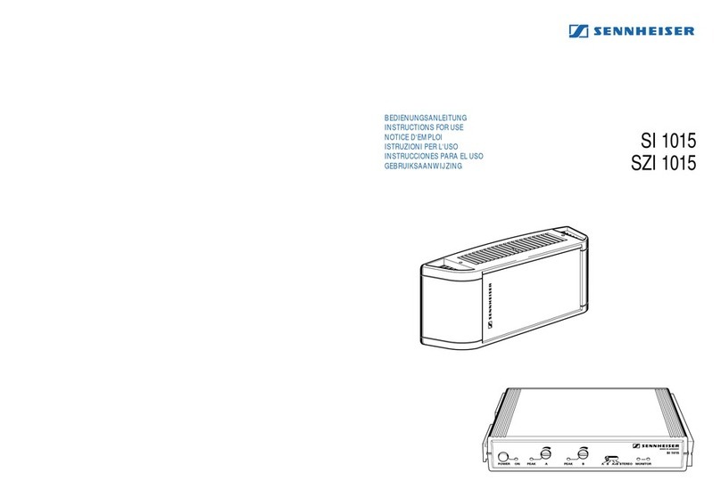
SI 1015
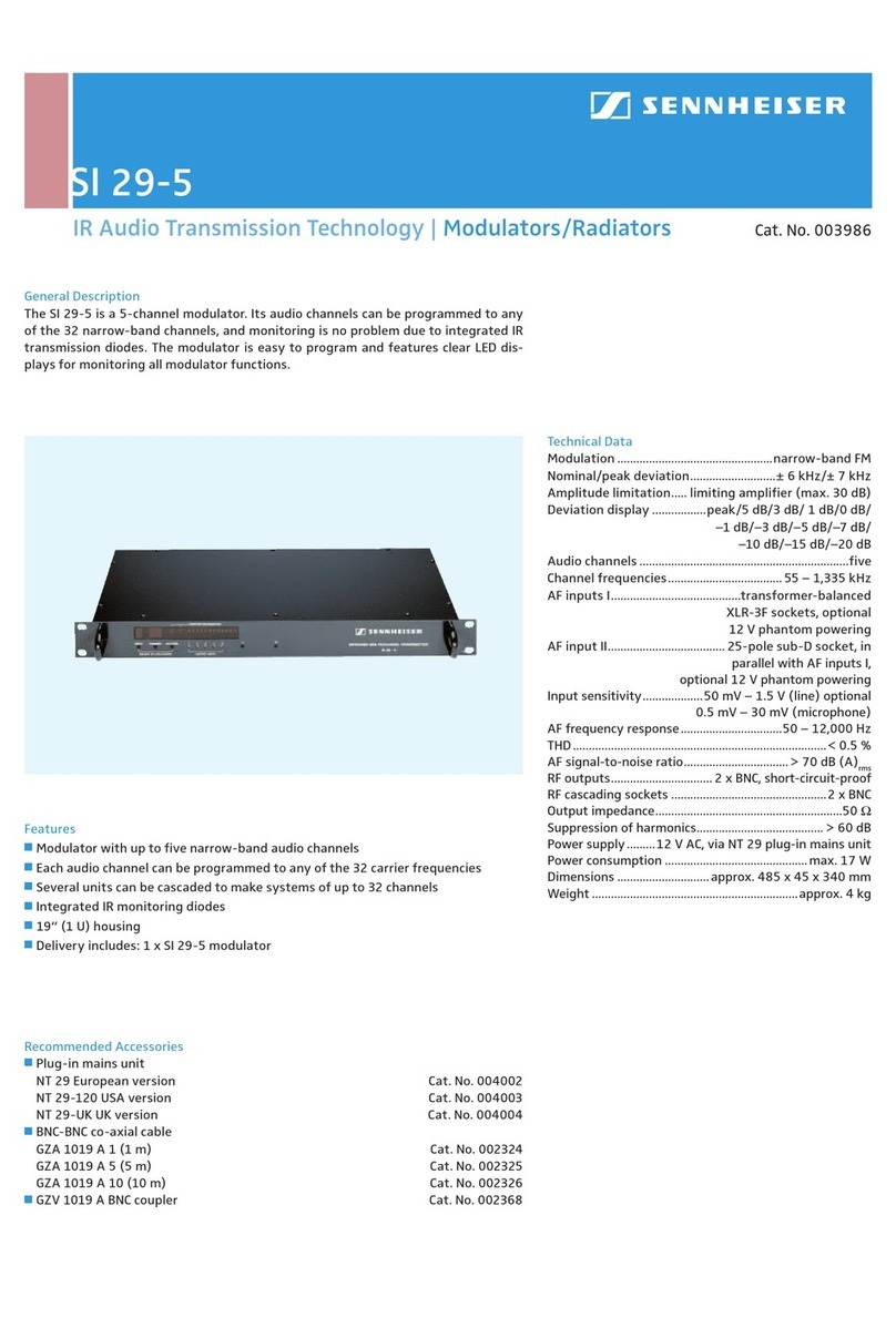
Features
j
Modulator for the carrier frequencies 2.3 and 2.8 MHz
j
Single-channel, two-channel or stereo operation, features
monitoring diodes and a separate barrier strip with RF and DC outputs for
connecting radiators
j
Delivery includes: SI 1015 modulator, two rack-mount ears
General Description
The SI 1015 wideband modulator uses the extremely reliable carrier frequencies 2.3
and 2.8 MHz and can be operated in single-channel, two-channel and stereo modes.
The modulator is fitted with two balanced XLR-3 audio inputs and IR monitoring
diodes. It can be used with SZI 1015 and SZI 1029 radiators, the signals for the
radiators are available at two RF sockets, or, alternatively, at a barrier strip. (N.B.:
The barrier strip – which also powers the connected radiators – can only be used
with SZI 1015 and SZI 1029-24 radiators.)
Technical Data
Modulation ....................................................... wideband FM
Nominal/peak deviation........................±40 kHz/±56 kHz
Carrier frequencies ....................................2.3 and 2.8 MHz
AF frequency response...............................50 – 15,000 Hz
Audio inputs......................................... 2 x XLR-3, balanced
Input impedance .......................................................... 600 Ω
Input sensitivity.....................................50 mV – 5 V (line),
optional: 1 mV – 100 mV (condenser
microphone, 12 V phantom powering)
0.4 mV – 40 mV (dynamic microphone)
RF outputs.............2 x BNC socket, in parallel with barrier
strip, terminating impedance 50 Ω
Operating voltage............................................. 24 – 30 V DC
Current consumption ............................................ < 140 mA
Dimensions ..................1/2 19“, 1 U (224 x 44 x 173 mm,
without rack-mount ears)
Weight .............................................................. approx. 800 g
Cat. No. 004252
Recommended Accessories
j
Mains unit
NT 1015-EU European version Cat. No. 004560
NT 1015-120 USA version Cat. No. 004561
j
BNC-BNC co-axial cable
GZA 1019 A 1 (1 m) Cat. No. 002324
GZA 1019 A 5 (5 m) Cat. No. 002325
GZA 1019 A 10 (10 m) Cat. No. 002326
j
GZV 1019 A BNC coupler Cat. No. 002368
j
GA 1031 CC Blank module Cat. No. 004253
Dimensions of the SI 1015
173 mm
44 mm
224 mm
IR Audio Transmission Technology | Modulators/Radiators
SI 1015
The SI 1015 wideband modulator can be switched between operation on one chan-
nel, operation on two channels and stereo operation. It uses the carrier frequencies
2.3 and 2.8 MHz which ensure excellent transmission reliability. Together with a
GA 1031 CC blank module, the compact SI 1015 can easily be mounted into a 19“ rack.
The modulator’s controls are shown in the drawing on the left: On the very left
of the front panel is the on/off switch, and the LED next to it shows whether a DC
voltage is present.
The AF levels of channels A and B can be adjusted with controls 4 and 6. The AF
level should be adjusted in such a way that the peak LEDs occasionally light up at
peak volumes. With the channel selector switch (7), the modulator can be switched
between mono operation on channels A or B, two-channel dual mono (A/B) and stereo
operation. In stereo operation the control amplifiers of the channels are coupled.
The transmitted IR signal can be checked on the modulator, as the SI 1015 features
two monitoring diodes (8). Please remember to use a receiver which operates on the
carrier frequencies 2.3 and 2.8 MHz.
The back panel of the modulator features the DC input socket (see diagram on the
left) where the modulator is connected to the mains via the NT 1015 mains unit.
There is a cable grip for the power cable which should be used when rack-mounting
the modulator as it prevents the connector from falling off or being pushed out
of the socket. The audio signals are fed to the modulator via two electronically
balanced XLR-3 input sockets (15 and 17, for channel B and A). The input sockets
have line sensitivity but can optionally be fitted with microphone sensitivity
for dynamic and condenser microphones (12 V phantom powering possible). The
RF signal is available at two BNC sockets (9 and 14) to which you can connect
SZI 1015, SZI 1029, SZI 1029-10 or SZI 1029-24 radiators.
Alternatively, the RF signal is available at the barrier strip: terminals 10 and 13 are
in parallel with the two BNC sockets. For connection, part of the sheath of a co-axial
cable must be removed, then about 1 cm of the neutral conductor must be stripped.
The copper braiding is then twisted and inserted into the frame earth terminal and
the neutral conductor into the terminal next to it (see drawing). When connecting
the last radiator of your RF chain, do not forget to use a 50 Ωterminating imped-
ance.
The modulator’s DC supply voltage is also present at terminals 11 and 12. The SI 1015
can thus power up to two SZI 1015 radiators or a single SZI 1029-24 radiator via
a two-core cable. You can also use co-axial cables with additional conductors for
direct current, e.g. a CVS 50-275 cable from Cordial. Your local Sennheiser dealer will
be delighted to supply you with more information on this easy installation method.
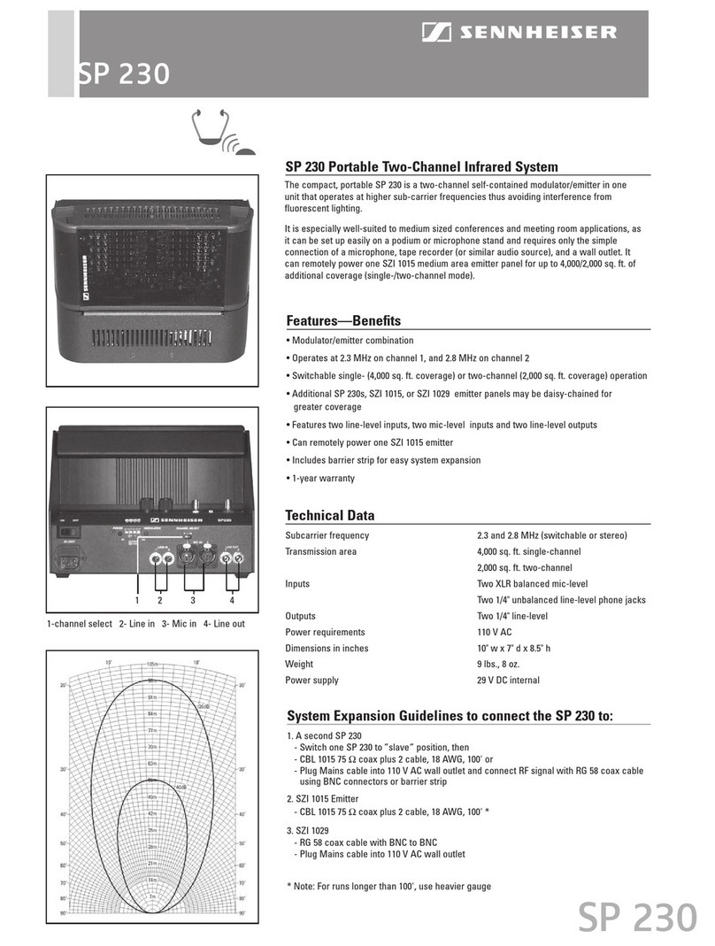
In general, the SI 1015 modulator can be used with the SZI 1015 radiator, all SZI 1029
variants, and the SZI 30 radiator. The earlier SZI 20 radiator cannot be used, as it
cannot work with the frequencies 2.3 and 2.8 MHz. Other older radiator models such
as the SZI 1219 A and SZI 1019 A series models are also not suitable.
Front panel of the SI 1015
1 On/off switch
2 Mains indicator
3 Peak LED for channel A
4 Level control for
channel A
5 Peak LED for channel B
6 Level control for
channel B
7 Channel selector
switch
8 IR monitoring diodes
123 4 5 6 7 8
Back panel of the SI 1015
9 RF output 1 (BNC)
10 RF terminal 1
11 DC output terminal 1
12 DC output terminal 2
13 RF terminal 2
14 RF output 2 (BNC)
15 Audio input B (XLR-3)
15 Cable grip
17 Audio input A (XLR-3)
18 DC input socket
(for NT 1015)
910 11 12 13 14 15 16 17 18
Mounting the SI 1015 into a rack: the modulator is
combined with a GA 1031 CC blank module to form
a 19“ unit (left), the cable grip prevents the power
cable from being pulled off (right).
Connecting a radiator to the barrier strip of the
SI 1015: Press down a lug with a screwdriver to
open the corresponding terminal
IR Audio Transmission Technology | Modulators/Radiators

Other manuals for SI 1015

2

Other Sennheiser Modulator manuals

Sennheiser SZI 1015 User manual

Sennheiser

Sennheiser SZI 1015 User manual

Sennheiser Dishwasher Dimensions

Sennheiser

Sennheiser Dishwasher Dimensions

Sennheiser SI 30 User manual

Sennheiser

Sennheiser SI 30 User manual

Sennheiser SI 120R Dimensions

Sennheiser

Sennheiser SI 120R Dimensions

Sennheiser SI 30 Dimensions

Sennheiser

Sennheiser SI 30 Dimensions

Sennheiser SZI 1012 User manual

Sennheiser

Sennheiser SZI 1012 User manual

Sennheiser SZI 30 Operating and maintenance instructions

Sennheiser

Sennheiser SZI 30 Operating and maintenance instructions

Sennheiser SI 1015 User manual

Sennheiser

Sennheiser SI 1015 User manual

Sennheiser SI 20 Dimensions

Sennheiser

Sennheiser SI 20 Dimensions

Sennheiser SI 29-5 Dimensions

Sennheiser

Sennheiser SI 29-5 Dimensions

Sennheiser SI 30 User manual

Sennheiser

Sennheiser SI 30 User manual

Sennheiser SI 30 User manual

Sennheiser

Sennheiser SI 30 User manual

Popular Modulator manuals by other brands

Kingray KDM401a instruction manual

Kingray

Kingray KDM401a instruction manual

Polytron HDM 2 T/IP user manual

Polytron

Polytron HDM 2 T/IP user manual

Blonder tongue MIDM-806C instruction manual

Blonder tongue

Blonder tongue MIDM-806C instruction manual

axing AVM 6-00 Operation instructions

axing

axing AVM 6-00 Operation instructions

Satlink WS-8901U user manual

Satlink

Satlink WS-8901U user manual

Tefi Vintage Lab GOLDEN ERA operating manual

Tefi Vintage Lab

Tefi Vintage Lab GOLDEN ERA operating manual

Jensen KVFM1 How to install and operate

Jensen

Jensen KVFM1 How to install and operate

Boss Audio Systems FM-MOD user manual

Boss Audio Systems

Boss Audio Systems FM-MOD user manual

Kenwood KCA-R2FMA instruction manual

Kenwood

Kenwood KCA-R2FMA instruction manual

Cisco D9477-1 Installation and operation guide

Cisco

Cisco D9477-1 Installation and operation guide

Philips SWS2104W Specifications

Philips

Philips SWS2104W Specifications

Lemco HDMOD-4 Operation manual

Lemco

Lemco HDMOD-4 Operation manual

Thor Broadcast H-XX-SDI-QAM-IPLL user manual

Thor Broadcast

Thor Broadcast H-XX-SDI-QAM-IPLL user manual

resi-linx digi-MOD HD-1000DM quick start guide

resi-linx

resi-linx digi-MOD HD-1000DM quick start guide

Hinds Instruments PEM-100 user manual

Hinds Instruments

Hinds Instruments PEM-100 user manual

GSS HDTV 1000 T Assembly instructions

GSS

GSS HDTV 1000 T Assembly instructions

GSS HDTA 614 T ASI Assembly & instruction manual

GSS

GSS HDTA 614 T ASI Assembly & instruction manual

FTE Maximal MODIG S user manual

FTE Maximal

FTE Maximal MODIG S user manual

manuals.online logo
manuals.online logoBrands
  • About & Mission
  • Contact us
  • Privacy Policy
  • Terms and Conditions

Copyright 2025 Manuals.Online. All Rights Reserved.