Sennheiser L 2015 User manual
Instructions for use
Notice d’emploi
System 2015

4
Instructions for use ................ ............ ................... ............. ................... ............ ......... 3
Notice d’emploi...................................................................................... ...................53
Istruzioni per l’uso141
Instrucciones para el uso187
Gebruiksaanwijzing233

Instructions for use
3
System 2015

4
Safety instructions
Never open an electronic unit! If units are opened by customers in breach of
thisinstruction, the warranty becomesnulland void.
Keep the units away from central heating radiators and electric heaters.
Never expose them to direct sunlight.
Use the units indry rooms only.
Use a damp cloth for cleaning the units. Do not use any cleansing agents or
solvents.
Thank you for choosing Sennheiser!
We have designed thes e produc ts to give you reliable operation over many
years. Over half a century of accumulated expertise in the design and
manufacture of high-quality electro-acoustic equipment have made
Sennheiser a world-leading company in this field.
Pl ease take a few mo ments to read these ins tructions carefully, as we w ant
you to enjoy your new Sennheiser products quickly and to the fullest.

5
Contents
Sa fety i nstructio ns ... ......... ...... .......... ......... ....... ......... ...... .......... ...... ......... ....... ........ 4
The 2015 System ................................................................................. .....................7
The operating principle of the 2015 System ....................... ................................... .... 7
Delivery includes .......................................................................................................8
Operating controls o f the EK 2015 receiver ........................................................9
Indications and displays on the receiver .................. ................................... ..............10
Operating controls of the SK 2015 transmitter .................................. .............12
Indications and displays on the transmitter ........................ ................................... ..13
Preparing the units for use .... ................................... .................................. ..........15
Transporting the transmitter and receiver .. .................................... .........................15
Inserting the accupack/batteries (transmitter and receiver) ................. ..............15
Connecting the receiver to hearing aids ...................................................... ..............16
Connecting sound sources to the transmitter ................................. .........................17
Attaching the transmitter or receiver to clothing .. ........................ .........................18
Using the receiver ...................................................................................................20
Switching the receiver on/off ......................... ........................ ................................... ..20
Activating/deactivating the lock mode ................................ ....................... ..............20
Adjusting the level of the received audio signal ................. ................................... ..21
Adjusting the level of the internal microphone .................. ................................... ..21
Switching the channel ... ................................... ........................ ................................... ..21
Displaying the frequency ...................... ................................... ................................... ..22
Operating menu of the EK 2015 receiver ................. ................................... ..............23
Using the transmitter . .................................. .........................................................24
Switching the transmitter on/off ................... .................................... .........................24
Muting the microphone ......................... ................................... ....................... ..............24
Activating/deactivating the lock mode ................................ ....................... ..............25
Displaying the frequency ...................... ................................... ................................... ..25
The operating menu of the transmitter .................... ................................... ..............26
Working with the operating menu ............................ ........................ .........................27
Operating menu of the SK 2015 transmitter .......................................................... ..29
Adjustment tips for the operating menu of the transmitter .............................. ..30
Troubleshooting ................................. .................................. ................................... 32
Error checklist . .. .. .... .. .. .. .. .. .. .. .. .. .... .. .. .. .. .. .. .. .. .. .... .. .. .. .. ... .. .. .. .. .... .. .. .. .. .. .. .. .. .. 32
Recommendations and tips .................. ................................... ................................... ..33
Care and maintenance ...........................................................................................34
Informatio n for al l u ser s
Informatio n for u sers of the
receiver
Informatio n for u sers of the
transmitter
Informatio n for the tec hni cal
expert

6
Configuration o f the units by the technic al expert ..........................................35
The configuration menu ............. ................................... .................................... ...........35
Working with the configurati on menu ....................... .................................... ........... 36
Structure of the configuration menu of the EK 201 5 receiver ................... ........... 38
Structure of the configuration menu of the SK 2015 transmitter ............ ........... 40
Adjustment tips for the configur ation menu ............ .................................... ...........42
Color marking of receivers .......... ........................ ................................... ....................... 45
Additional information ............... ................................... .................................... ........... 47
Spec ifications ......................... .................................. ................................... .............49
Connector assignment .... .................................... ................................... ....................... 50
Accessories ...............................................................................................................51

7
The 2015 System
The 2015 System allows the integration of people with hearing problems in
schools and universities, at the workplace and in their free time. Design and
characteristics of the 2015 System are ideally suited to the needs of the
users. Operation is simple and easy to learn. The units are small, lightweight
and unobtrusive when worn.
The operating principle of the 2015 System
The speaker, for example the teacher, wears the SK 2015 transmitter. The
person with hearing problems, the pupil in this case, wears the EK 2015
receiver. The receiver can be equipped either with a connecting cable for a
hearing aid or with headphones. Without wires and with full freedom of
movement, the pupil can now hear the teac her as if he were sitting right next
to him. For the time in which the teacher is speaking, ambient noise is
reduced markedly, so that the dialog between teacher and pupil has priority
at all times. When the teacher is not speaking, the pupil can hear his fellow
pupils either via the microphones in the hearing aid or via the internal
microphone in the receiver. The 2015 System gives reliable assistance, even
in difficult listening situations. The transmitting power is sufficient for
relatively large distances. The MKE 2015-2 screw-on microphone ensures a
hig h degree of intelligi bility. Lo ud bac kground noise and bad acoustics are
faded out by the ME 2015-H neckbandmicrophone (optional accessory).The
wide range of accessories allo ws the receiver to be connected to almost any
hearing aid; it can be coupled to the latter either electrically or inductively.
Transmitter and receiver are powered via the BA 2015 accupack. The
operating time of the accupack issufficient for a normal working day (up to
12 hours). The charging contacts on transmitter and receiver allow the units
to be charged in the L 2015 charger without the necessity of removing the
accupack.
If no mains supply is available for recharging the accupack, you can
alternatively use 1.5 V AA size batteries. When powered by batteries,
transmitter and receiver can also be used for up to 12 hours.
8
Addi tional audio sou rces (e.g . CD pla yer, tel evision, so und ca rd of a
computer) can be connected to the 3.5 mm jack socket of the transmitter.
Especially for integrative schools, there is the advantage that you can
combine the 2015 System with the Soundfield EMP 2015 System. In addition,
transmitters and receivers of the ev olution wireless series can be used
together with the 2015 System. For details, please visit ou web site at
www.sennheis er.com.
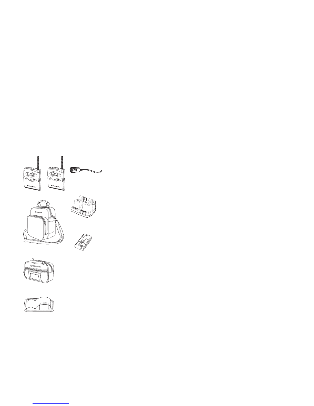
Delivery includes
The 2015 System consists of the following components:
y1 SK2015 transmitter
y1 MKE 2015-2 clip-on microphone
y1 EK 2015 receiver
y2 BA 2015 accupacks
y1 L 2015 c harger
yInstructions for use
y1 EZB2015 system case
incl. transport case and transport holding device(for EK 2015 and SK 2015)
as well as shoulder strap and neck strap
Note:
All components of the 2015 System are also available separately
(see “Accessories” on page 51).
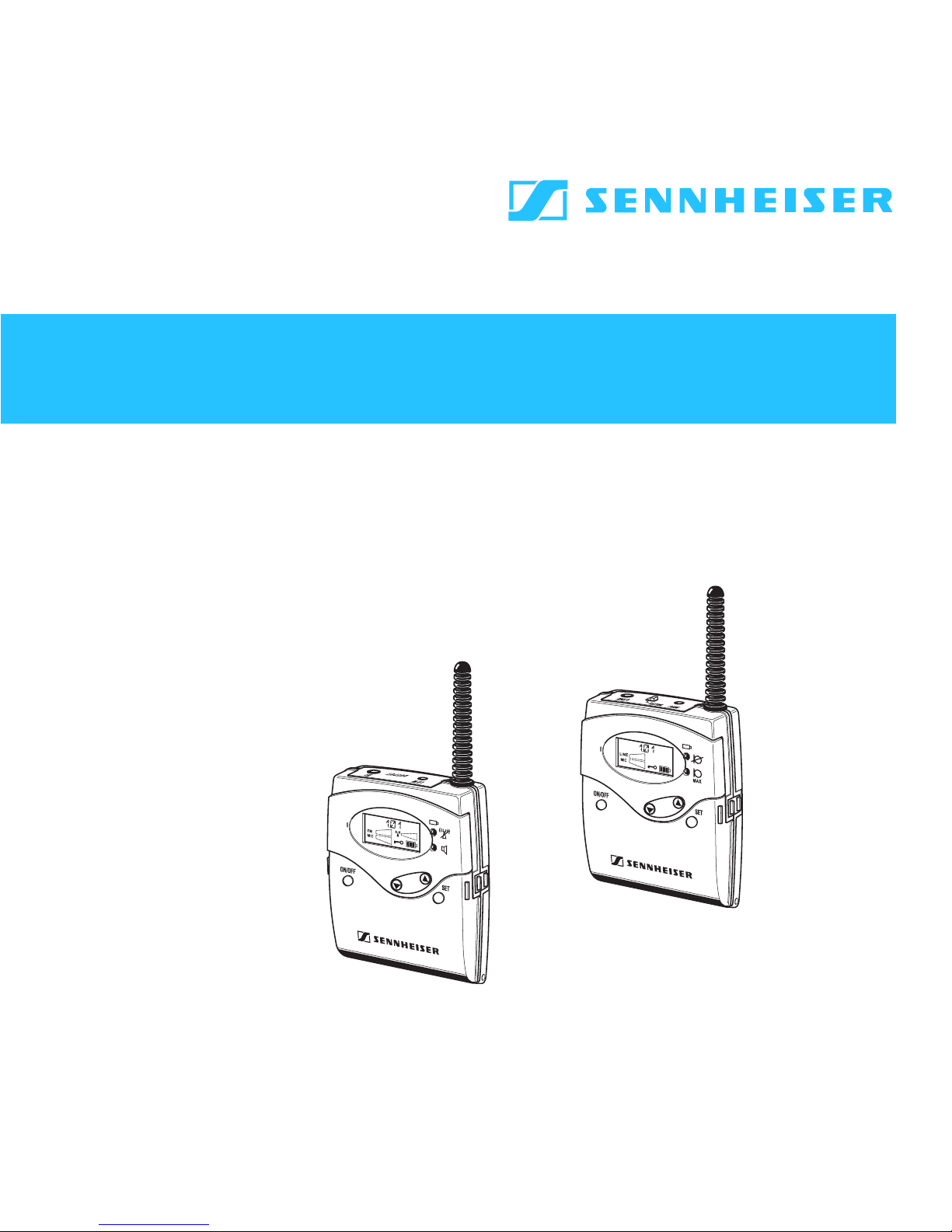
EK 2015 SK 2015
Tr an spo rt cas e
MKE 2015-2
EZB 2015
Tr ans por t ho ldi ng d evice
BA 2015
L 2015

9
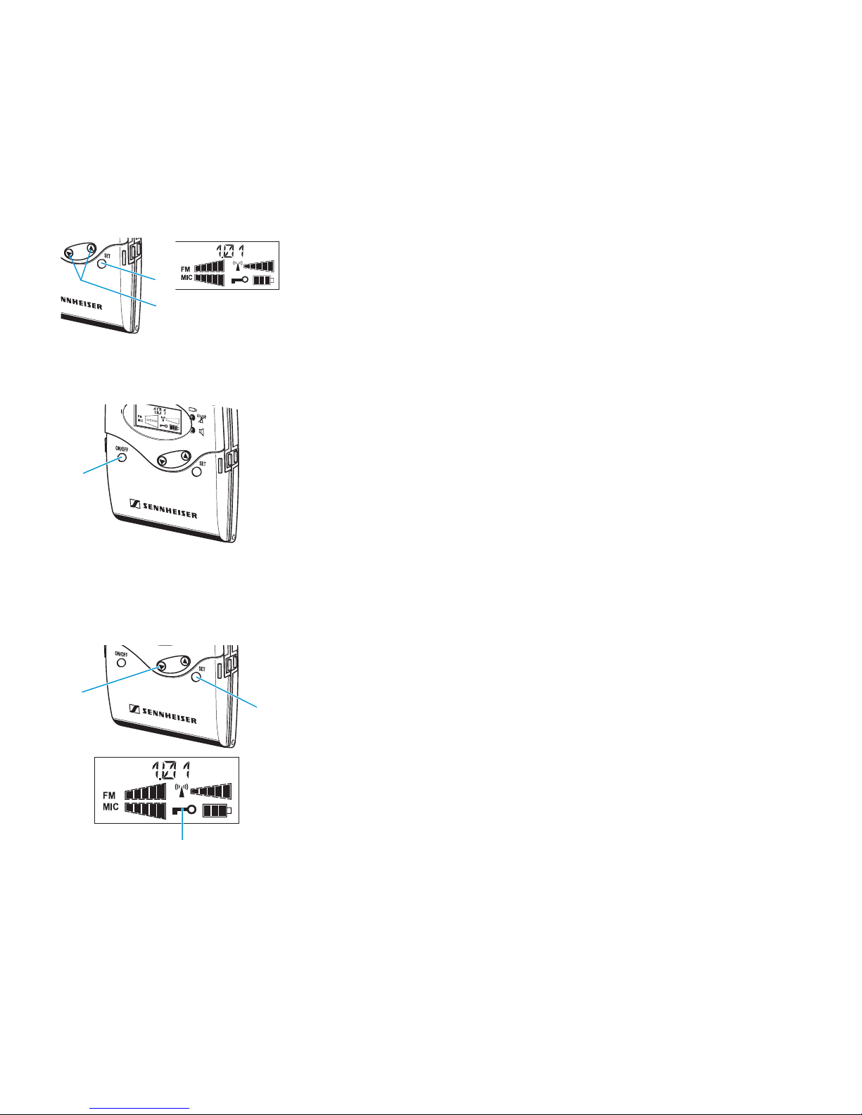
Operating controls of the EK 2015 receiver
Operating controls LC display panel
Headphone output (HI), 3.5 mm jack socket
Output for hearing aids (LOW), 2.5 mm jack socket
Antenna
Red LED forbattery status and missing transmitter
RF s ig nal in di cation
Green LED for audio signal indication
Charging contacts
SET button
/rocker button (UP/DOWN)
Battery compartment
Battery compartment cover
Unlocking button
ON/OFF button with ESC function
Interna l microph one
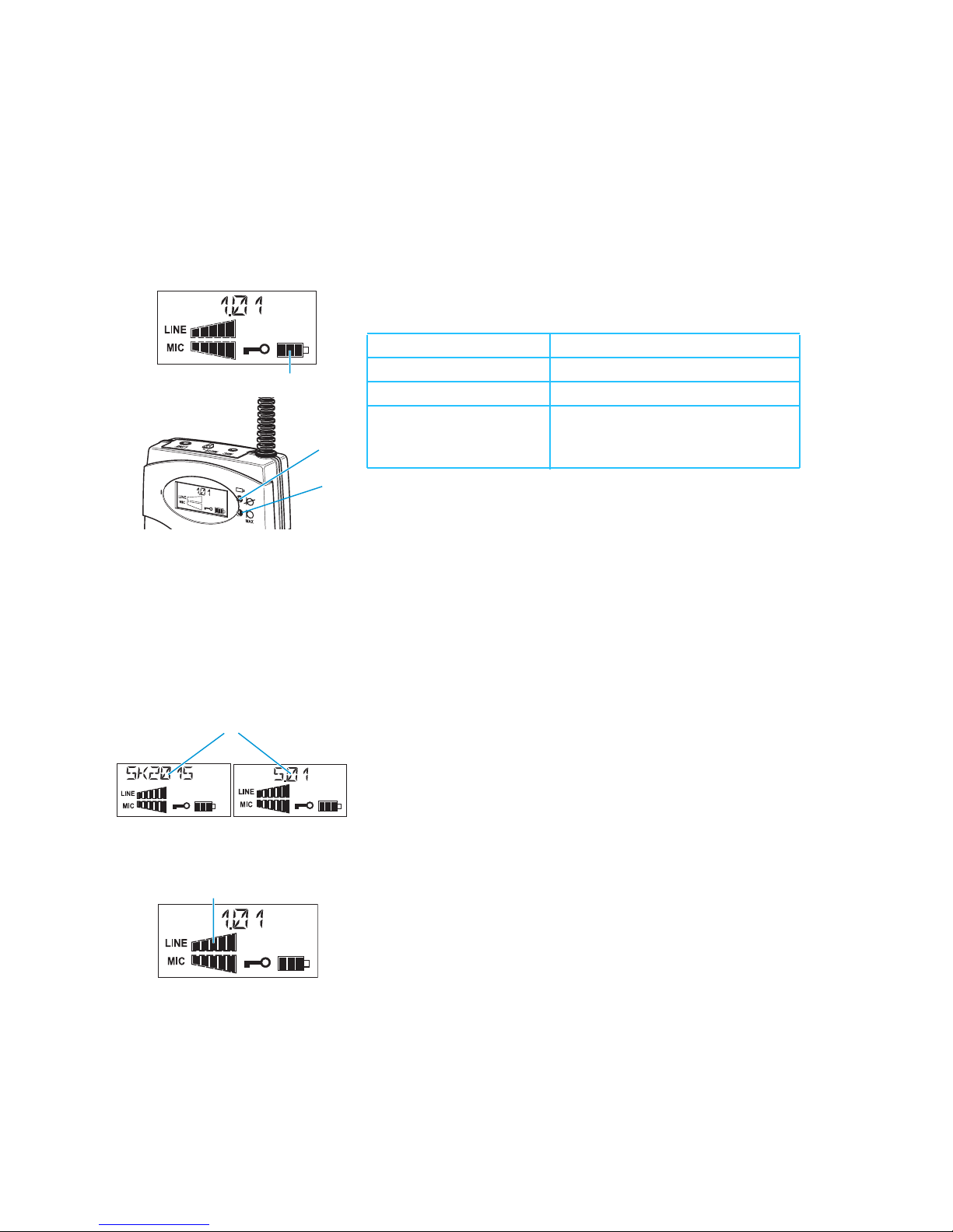
LC display
Alphanumeric display
5-step level display for received audio signal (FM)
5-step display for microphone level (MIC)
of internal microphone (only with switched-on
internal micro pho ne)
Loc k mo de icon (lo ck mo de is activated)
4-step battery status display
5-step level display for received RF signal
Note:
Depending on the individu al c onfiguration of yo ur
receiver, some of the displays shown here may not
appea r o n the display panel.
10
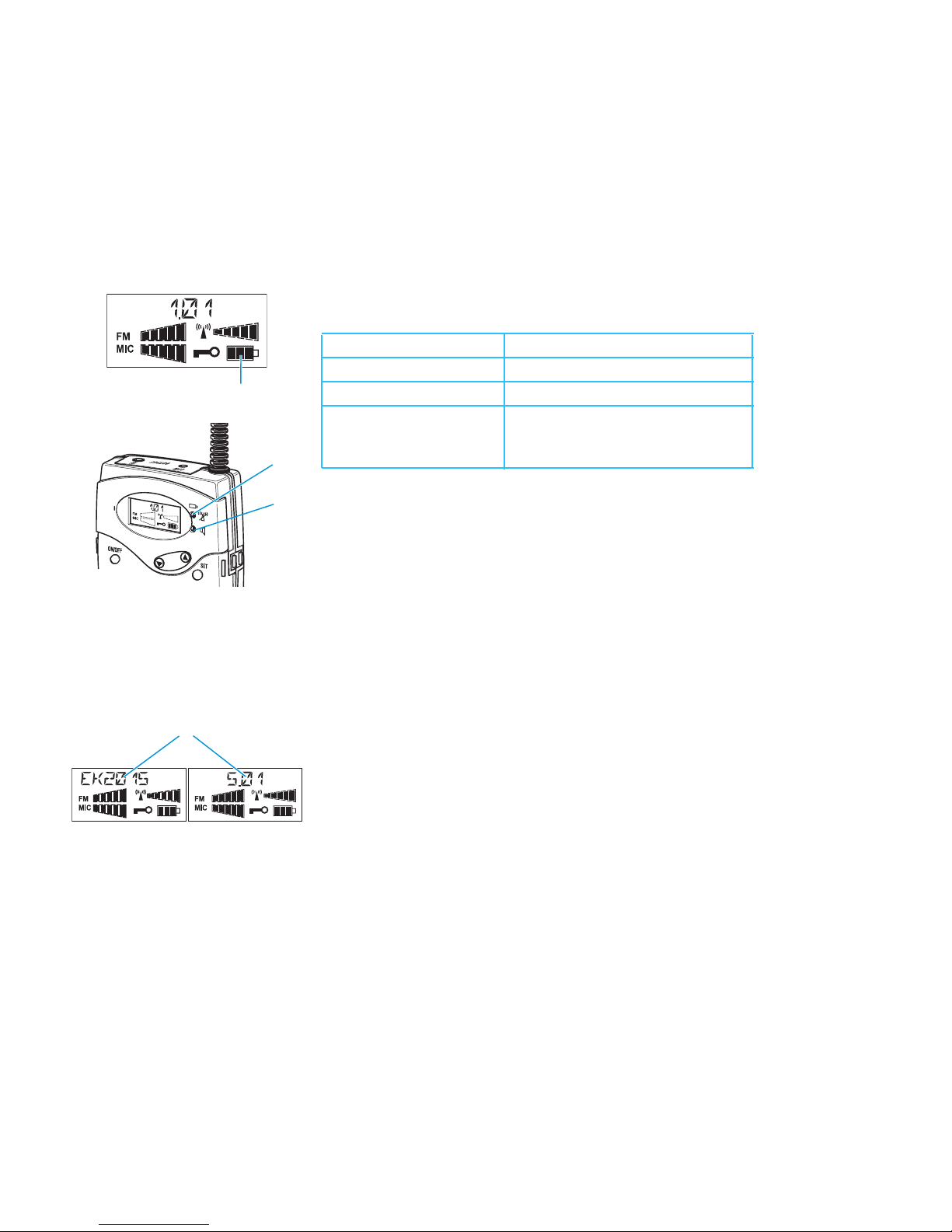
Indications and displays on the receiver
Battery status indication
The 4-step battery status display on the display panel and the red LED
provide information on thecapacityof the BA 2015 accupack or the batteries:
Warningindication for missing RF signal
The red LED lights up constantly when no RF signal is being received, e.g.
because the microphone of the transmitteris muted.
Audio signal indication
The green LED lights up when an audio signal of sufficient strength (e.g.
the voice of the speaker) is being received.
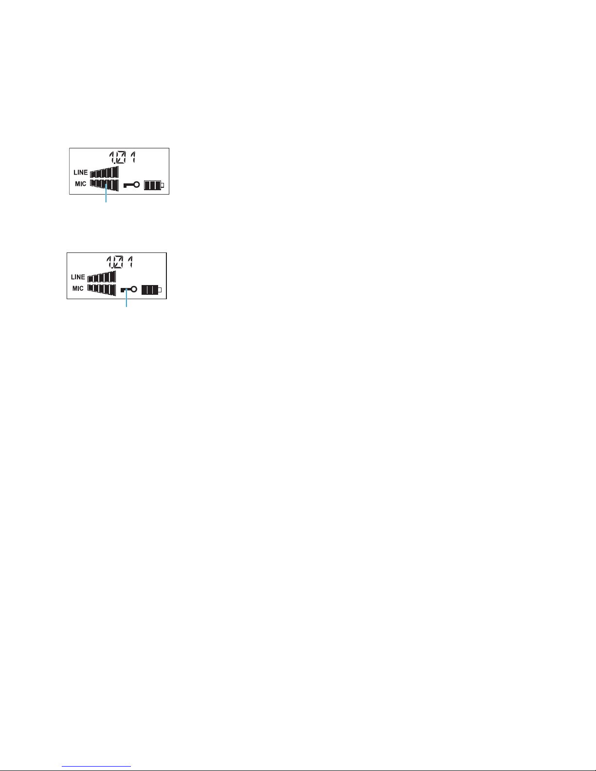
Alphanumeric display
After switching on thereceiver, the alphanumeric display first displa ys the
name of the receiver. After approx. three seconds, the standard display
appears, indicating the channel bank (5) and the channel (01).
3 segments: capacity approx. 100 %
2 segments: capacity approx. 70 %
1 segment: capacity approx.30 %
Battery status display
and red LED flashing:
LOW BAT (you should immediately
replacethe accupack or the
batteries)

11
Displayfor theaudio level
The display shows the level of the received audio signal.
Display for microphone level (internal microphone)
The display shows the level of the internal microphone.
Note:
Depending on the configuration of yo ur receiver, this displ ay may not
appear o n the display panel.
Display for the RF level
The display shows the level of the received RF signal. The more segments
displayed, the better the reception.
Display for lock mode
If the lock mode isactivated, the lock mode icon appears on the standard
display. If the lock mode is deactivated, the lock mode icon disappears from
the standarddisplay.
Display backlighting
Afterpressing a button, the display remains backlit for approx. 15 seconds.
12
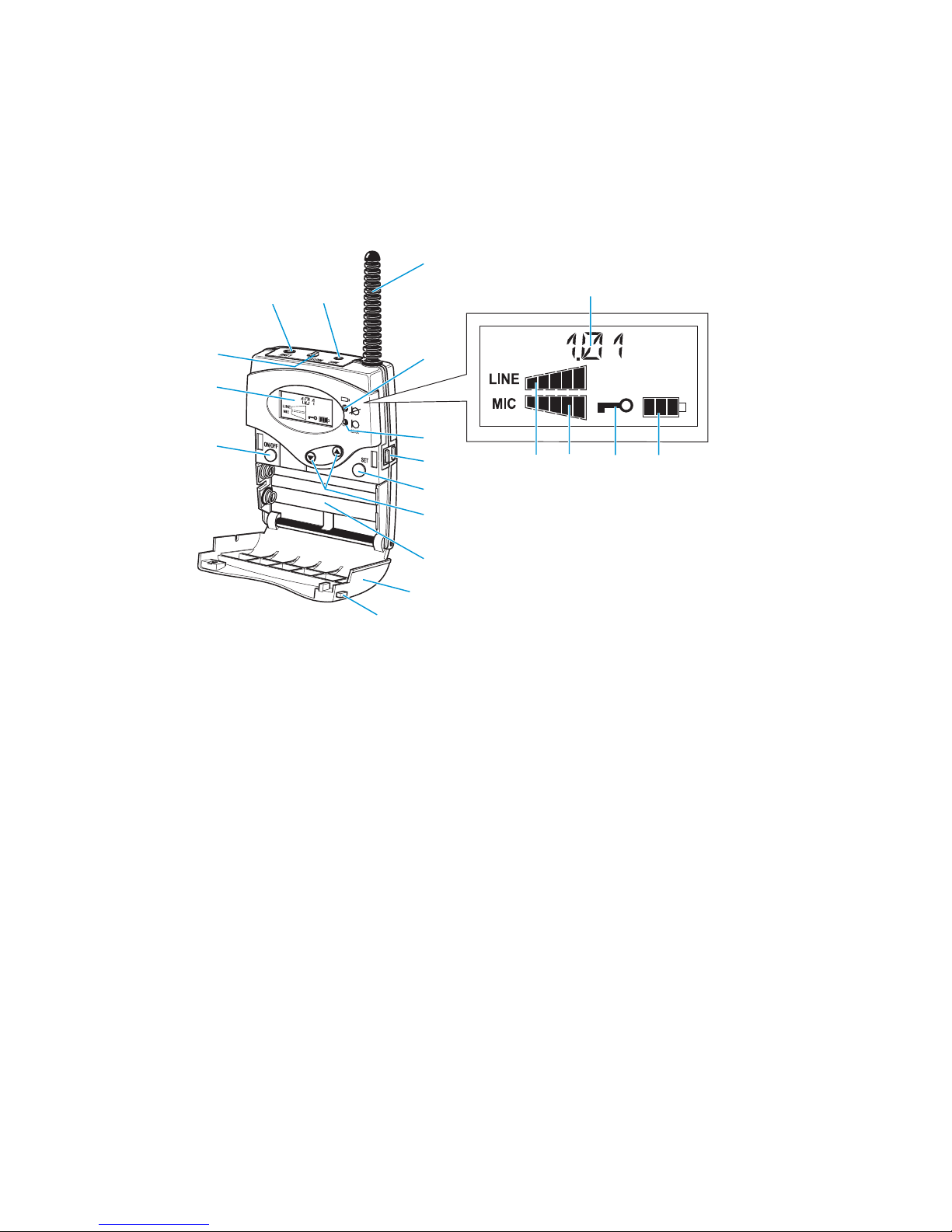
Operating controls of the SK 2015 transmitter
Op erating contro ls LC d is play p anel
Audio input (LINE), 3.5 mm jack socket
Micro pho ne i np ut (MIC), 2. 5 mm jack soc ket
Antenna
Red LED forbattery status and muting indication
Yellow LED for audio peak
Charging contacts
SETbutton
/ro cker bu tton (UP /DOWN )
Battery compartment
Battery compartment cover
Unlocking button
ON/OFF button with ESC function
LC display
MUTE switc h for microphone input
Alphanumeric display
5-s tep display for l ine level (LINE)
5-s tep display for m icrophone level (MIC)
Lock mode icon (lock mode is activated)
4-step battery status display
Note:
Depending on the individual configuration of your
transmitter, some of the displays shown here may
not appear on the display panel.
13
Indications and displays on the transmitter
Battery status indication
The 4-step battery status display on the display panel an d the red LED
provide information on the capacity of theBA 2015 accupack or the batteries:
MUTE indication
The red LED lights up constantly when the microphone of the transmitter
ismuted.
Audio peak indication
The yellow LED should only light up briefly during peak level passages.
When it lights up constantly, the l ine or microphone input level is too high.
Alphanumeric display
Afterswitching on the transmitter, the alphanumeric display first displays
the name of the transmitter. After approx. three seconds, the standard
display appears, indicating the channel bank (5) and the channel (01).
Display for line level
The display fo r line level (LINE) shows the level of the line input. The
display should showfulldeflection only during the loudest passages.
3 segments: capacity approx. 100 %
2 segments: capacity approx. 70 %
1 segment: capac ity approx. 30 %
Batterystatusdisplay
and red LED flashing:
LOW BAT (you should immediately
replace the accupack or the
batteries)
14
Disp lay f or micropho ne level
The display for mic rophone level (MIC) shows the level of the connected
microphone. The display should show full deflection only when you speak
very loudly.
Disp lay f or lo ck mode
If the lo ck m ode is activa ted, the lo ck mo de icon appears on the standard
display. If the lock mode is deactivated, the lock mode icon disappears from
the standard display.
Display backlighting
After pressing a button, the display remains ba cklit for approx. 15 seconds.
15
Preparing the units for use
Transmitter and receiver have been adapted by your technical expert to suit
your individual applications.
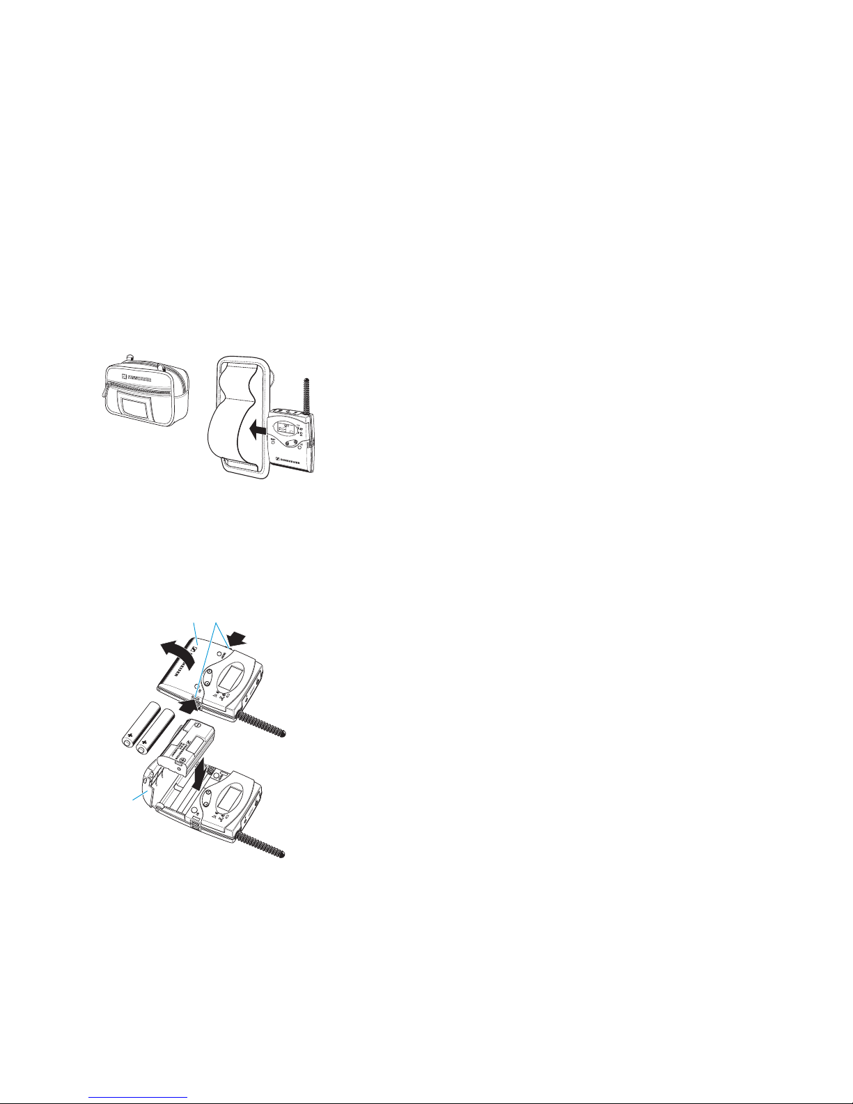
Transporting the transmitter and receiver
In addition to the EZB 2015 system case offering room to store all
components of the system, delivery also includes a transport case. This is
suitable for the day-to-day transport of a transmitter and a receiver and of
two replacement accupacks.
Push the transmitter and the receiver into the transport holding device as
shown on the left. This prevents damage to the units during transport and
fits snugly into the transport case.
Insertingthe accupack/batteries (transmitter andreceiver)
For powering the units, we rec ommend using the supplied BA 2015 accupack.
The accupack ca n be recharged in the L 2015 charger while remaining in the
unit (see operating manual of the charger). If no mains supply is available for
recharging the accupack, you can alternatively use 1.5 V AA size batteries.
Press the two unlocking buttons and open the battery compartment
cover .
Insert the accupack or the batteries as shown on the left. Please observe
correct polarity when inserting the accupack or the batteries.
Close the battery compartment. The battery compartment cover locks
into place with an audible click.
Note:
yFor accupack operation, only use the BA 2015 accupack in order to
ensure optimum operational reliability. Batteries and rechargeable
Transport holding
Transport
case
device

16
battery cells have different discharging curves. Transmitter and
receiver are able to identify the BA 2015 accupack and to use its
capacity to the full. They also adapt the battery status display
according to the type of power supply used (batteries or accupack).
Individu al rechar geab le battery c el ls w ill not be i dentified as accupac k s.
yIf you do not use the transmitter or receiver, remove the accupack or
the batteries. After three months at the latest, the accupacks will need
a refresh charge in the L2015 charger.
If you do not use the transmitter or receiver for extended periods of
time (e.g. while you are on holiday), we recommend sto ring it in the
L 2015 cha rger which is connected to the m ains. This prevents damage
to th e acc upa ck d ue t o to ta l d isc har ge.
Connecting the receiver to hearing aids
Connecting the receiver to hearing aids with audio input
Connect a hearing aid with audio input to the receiver’s 2.5 mm jack
socket (HI) . Suitable connecting cables (see “Accessories” on page 51)
are available from your Sennheiser dealer.
Connecting the receiver to a hearing aid without audio input
Connect the EZT 2015 induction neck loop or the EZI 120 induction
couplers for hearing aids without audio input to the receiver’s 3.5 mm jack
socket (LOW) . Suitable connecting cables for the induction couplers
(see “Accessories” on page 51) are availablefrom your Sennheiser dealer.
Con necting the head pho nes
You must only connect headphones with a stereo jack plug and a minimum
impedance of 32 Ωto the receiver.
Connect the headphones to the receiver’s 3.5 mm jack socket .

17
Connecting sound sources to the transmitter
Connecting the microphones to the transmitter
In addition to the supplied MKE 2015-2 clip-on microphone, a screw-on
microphone (MKE 2015-0) and a neckband microphone (ME 2015-H) are
available as optional accessories. DC powering of these condenser
microphones is via the microphone input.
Co nn ect th e 2 .5 mm jac k pl ug of the microphone or the microphone
cable to the transmitter’s 2.5 mm jack socket (MIC) .
Via the operating menu, adjust the sensitivity of the microphone input
(see “Adjusting the microphone sensitivity” on page 30).
Attaching and pos itioning the micro phones
The MKE 2015-2 clip-on microphone and the MKE 2015-0 screw-on
microphone with omni-directional pick-up pattern pick up sound equally
from all directions. They are the best choice if movements of the speaker’s
head have to be compensa ted fo r. However, they should be attached as close
as possible to the sound so urce.
Use the microphone clip to attach the MKE 2015-2 clip-on microphone to
clothing (e.g. tie, lapel). Atta ch the microphone at a maximum distance of
25 cm from your mouth.
When using the MKE 2015-0 screw-on microphone (optional accessory),
wear the transmitter around your neck using the EZG 2015 pouch with neck
strap. Adjust the length of the neck strap so that the distance between the
microphone and your mouth is 25 cm at the most.
The ME 2015-H neckband microphone has a super-cardioid pick-up pattern.
Adjust the ME 2015-H so that a comfortable and secure fit is ensured.
Position the microphone at the corner of your mouth.
Make sure that the sound inlet is direc ted towards your mouth. The sound
inlet is marked with a little dot.

18
Connecting audio sources to the transmitter
You can connect audio sources such as a CD player, a television, or the sound
card of a computer to the line input of the transmitter.
Connect the 3.5 mm jack plug ofthe connecting cable to the transmitter’s
3.5 mm jack socket (LINE) .
Via the operating menu, adjust the sens itivity of the line input (see
“Adjusting the sensitivity of the line input” on page 30).
Note:
If the transmitter is configured so that the line input is switched off, the
display for l ine level is not show n on the display panel . Consult your
technical expert for details.
Attaching the transmitter or receiver to clothing
Attaching the transmitter or receiver to clothing using the belt clip
Using the supplied belt clip, you can attach the transmitter or receiver to
clothing (e.g. belt, waistband).
The clip is detachable so that you can also attach the transmitter or receiver
with the antenna pointing downwards. To do so, withdraw the clip from its
fixing points and attach it the other way round.
19
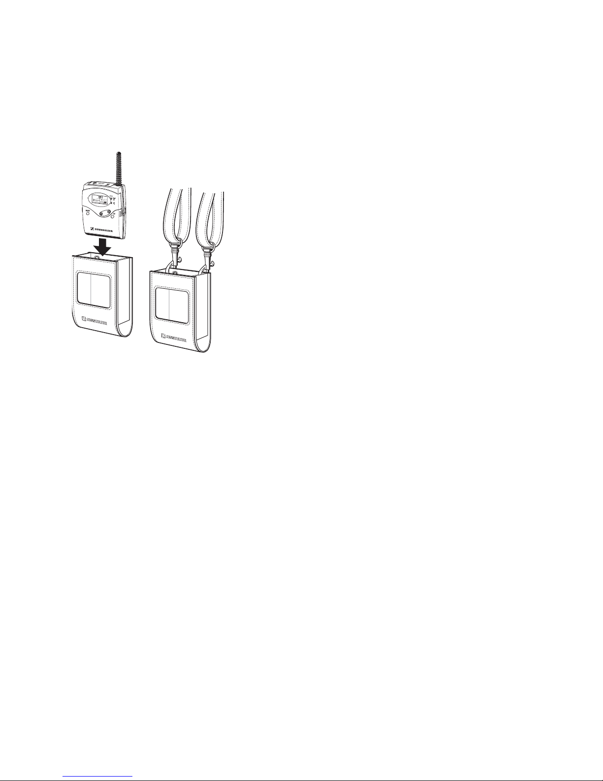
Wearing the transmitter or receiver around your neck
Using the EZG 2015 pouch with neck strap (optional accessory), you can wear
the transmitter or receiver around your neck.
Insert the transmitter or receiver into the pouch.
Use the snap hook to attach the neck strap to the eyelet of the pouch as
shown.
Note:
When using the transmitter with the MKE 2015-0 screw-on microphone
(optional accessory), adjust the length of the neck strap so that the
distance between the microphone and your mouth is 25 cm at the most.
20
Using the receiver
After you have switched on the receiver, itcan then be operated with the SET
buttonand the /rocker button (UP/DOWN), making it very easy to
use for children. All settings become effective immediately. The display then
switches back to the standard display.
Switching the receiver on/off
Press the ON/OFF button to switch the receiver on. The display first
displays the name of the receiver for approx. three seconds and then
switches to the standard display.
To switch the receiver off, press the ON/OFF button u ntil “O FF” ap pears
on the display.
Activating/deactivating the lock mode
The receiver has a lock mode that prevents accidental programming or
sw itching off during operatio n.
Press the SET button and keep it pressed.
Press the button (DOWN) . “LOCK” appears on the display. The lock
mode is activ ated a nd the loc k m ode ico n appears on the standard
display.
To deactivate the lock mode, press the SET button again and keep it
pressed.
Press the button (DOWN) . “UNLOCK” appears on the display. The
lock mode is deactivated and the lock mode icon disappears from the
standard displ ay.
Other manuals for L 2015
10
Table of contents
Languages:
Other Sennheiser Radio manuals


