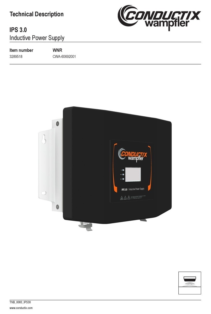
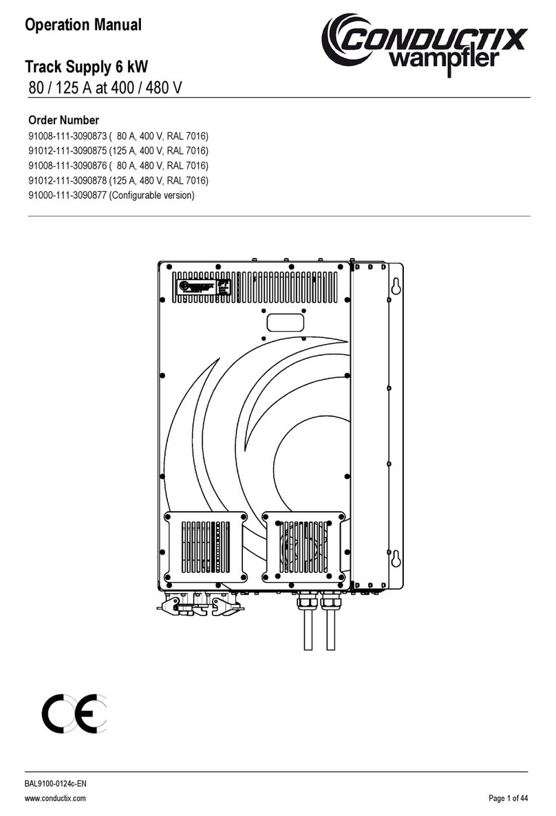
Conductix-Wampfler 91008-111-3130923 User manual

Operating Instructions
Track Supply 16 kW IP54
80 A/125 A at 400 V/480 V
BAL9100-0138i-EN
www.conductix.com translated document page 1 of 56
Order Number
91008-111-3130923 ( 80 A, 400 V, RAL 7035 - light gray)
91012-111-3130924 (125 A, 400 V, RAL 7035 - light gray)
91008-111-3130925 ( 80 A, 480 V, RAL 7035 - light gray)
91012-111-3130926 (125 A, 480 V, RAL 7035 - light gray)
91000-111-3130914 (configurable version)
Figure shows conditioned variant

Operating Instructions
Track Supply 16 kW IP54
80 A/125 A at 400 V/480 V
BAL9100-0138i-EN
www.conductix.com translated document page 2 of 56
Contents page
1General Advice.................................................................................................................................................................5
1.1 Information about these Operating Instructions......................................................................................................5
1.2 Limitation of Liability .............................................................................................................................................5
1.3 Copyright..............................................................................................................................................................6
1.4 Spare Parts ..........................................................................................................................................................6
1.5 Material Defects....................................................................................................................................................6
1.6 Technical Support.................................................................................................................................................6
2Safety Advice ...................................................................................................................................................................7
2.1 Explication of Symbols..........................................................................................................................................7
2.2 Personnel Requirements.......................................................................................................................................8
2.2.1 Qualification .........................................................................................................................................................8
2.2.2 Unauthorized Personnel........................................................................................................................................8
2.2.3 Instruction ............................................................................................................................................................8
2.3 Intended Use........................................................................................................................................................9
2.4 Protective Measures to be taken by the Operator/User ..........................................................................................9
2.5 Specific Hazards.................................................................................................................................................10
3Short Technical Description ............................................................................................................................................11
4Appearance....................................................................................................................................................................11
4.1 Standard Version –Forced Air Cooling................................................................................................................11
4.2 Track Supply IP54 (Air-Conditioned)....................................................................................................................12
5Technical Data ...............................................................................................................................................................13
5.1 Electrical Power Data..........................................................................................................................................13
5.2 Electrical Input Values | Specifications for Versions with 400 V ............................................................................13
5.3 Electrical Input Values | Specifications for Versions with 480 V ............................................................................14
5.4 Physical Data .....................................................................................................................................................14
5.4.1 Variant with Ventilation .......................................................................................................................................14
5.4.2 Variant with Air-Conditioning ...............................................................................................................................14
5.5 Environmental Conditions ...................................................................................................................................15
5.6 Mechanical Specifications...................................................................................................................................17
5.7 Connections | Track Supply IP54.........................................................................................................................19
5.8 Design Standards ...............................................................................................................................................21

Operating Instructions
Track Supply 16 kW IP54
80 A/125 A at 400 V/480 V
BAL9100-0138i-EN
www.conductix.com translated document page 3 of 56
5.8.1 Design Standards for 400 V Versions..................................................................................................................21
5.8.2 Additional Design Standards for 480 V Versions..................................................................................................21
5.9 Safety Features of the Track Supply Module........................................................................................................21
5.10 Grounding ..........................................................................................................................................................21
5.11 ESD Protection...................................................................................................................................................22
5.12 Illumination and Plug Socket | Track Supply IP54 ................................................................................................22
6Options ..........................................................................................................................................................................23
6.1 Variant with Air Conditioning Unit (Side Mounting) ...............................................................................................23
6.2 Integrated Tuning Unit (only in Combination with Air Conditioning Unit) ................................................................23
7Track Supply Module......................................................................................................................................................25
7.1 Indicator Circuit Board of the Track Supply ..........................................................................................................26
7.2 LED-Display .......................................................................................................................................................26
7.3 Version Number of the Software..........................................................................................................................28
7.4 Modes of Operation ............................................................................................................................................28
7.5 Language Setting, Time and Date .......................................................................................................................29
7.6 Warning Messages.............................................................................................................................................30
7.7 Error Codes........................................................................................................................................................30
8Fuses.............................................................................................................................................................................33
8.1 Semiconductor Main Fuses | Track Supply Module..............................................................................................33
8.2 Other Protective Devices (Fuses)........................................................................................................................33
9Transport, Packaging and Storage..................................................................................................................................34
9.1 Transport............................................................................................................................................................34
9.1.1 Safety Instructions for Transport..........................................................................................................................34
9.1.2 Transport Inspection ...........................................................................................................................................34
9.2 Packaging ..........................................................................................................................................................35
9.3 Storage of Packages...........................................................................................................................................35
10 Installation......................................................................................................................................................................36
10.1 Who is allowed to do the Installation?..................................................................................................................36
10.2 General Installation Recommendations ...............................................................................................................36
10.3 Place and Conditions of Installation.....................................................................................................................37
10.4 Electrical Regulations .........................................................................................................................................37
10.5 Electrical Connection ..........................................................................................................................................38
10.5.1 Power Connection ..............................................................................................................................................38

Operating Instructions
Track Supply 16 kW IP54
80 A/125 A at 400 V/480 V
BAL9100-0138i-EN
www.conductix.com translated document page 4 of 56
10.5.2 Connect Track Cable ..........................................................................................................................................39
10.5.3 Connection of the Track Cable with the Option Integrated Tuning Unit..................................................................40
11 Warnings and Precautions..............................................................................................................................................42
12 Commissioning...............................................................................................................................................................43
12.1 Safety.................................................................................................................................................................43
12.2 System Conditions..............................................................................................................................................44
12.3 System Protection...............................................................................................................................................44
13 Start and Operation ........................................................................................................................................................44
14 Switch Off ......................................................................................................................................................................45
15 Manual Operation...........................................................................................................................................................46
16 Emergency Measures.....................................................................................................................................................47
17 Fault Diagnosis...............................................................................................................................................................48
18 Maintenance and Servicing.............................................................................................................................................49
18.1 Safety.................................................................................................................................................................49
18.2 Maintenance Schedule Track Supply IP54 (air cooling)........................................................................................50
18.3 Maintenance Schedule Track Supply IP54 (air-conditioned variant)......................................................................51
19 Repair............................................................................................................................................................................52
20 Disassembly and Disposal..............................................................................................................................................53
20.1 Safety.................................................................................................................................................................53
20.2 Reuse ................................................................................................................................................................53
20.3 Disassembly.......................................................................................................................................................54
20.4 Disposal .............................................................................................................................................................54
21 Spare Parts....................................................................................................................................................................55
22 Tools..............................................................................................................................................................................56
This operating instruction is based on the following Documentation-No.: OM09100-0138e-EN!
Important:
The names used in the following document are copyrighted as brands and are in the property of the respective companies. We
reserve the right for technical modifications of illustrations and specifications in these operating instructions that serve for the
improvement of the system and its functions. For system details please see the respective documentation. Always observe the
system documentation for any works at the system or for the operation of the system. Reprinting and copies, even in excerpt, only
with our approval.
© Conductix-Wampfler GmbH 2018

Operating Instructions
Track Supply 16 kW IP54
80 A/125 A at 400 V/480 V
BAL9100-0138i-EN
www.conductix.com translated document page 5 of 56
1General Advice
1.1 Information about these Operating Instructions
This document facilitates safe and efficient handling and use of the equipment.
It is an integral part of the equipment and must be kept in its immediately vicinity to allow access by personnel at any time. Prior to
commencing any work, the personnel must have carefully read and understood these operating instructions. It is a basic
requirement for safe working that all safety and procedural instructions contained in these operating instructions are complied
with.
Local accident protection regulations and general safety guidelines for the application field of the device also apply.
Illustrations in this documentation are for basic comprehension and may deviate from the real design of the equipment.
In addition to these operating instructions, the attached instructions for installed components also apply.
1.2 Limitation of Liability
All information and instructions in these operating instructions have been compiled with due regard to the standards and
regulations in force, best engineering practice, and the findings and experience we have accumulated over many years.
The manufacturer is in no way liable for damages resulting from:
◼Failure to comply with these operating instructions
◼Improper use
◼Use by untrained personnel
◼Unauthorized modifications
◼Technical changes
◼Use of unauthorized replacement parts and accessories
The actual scope of delivery may differ from the explanations and illustrations described here for special variants, if additional
order options are utilized, or due to the latest technical changes.
The obligations agreed upon in the delivery agreement and our General Terms of Business apply, as well as the delivery
conditions of the manufacturer and all regulations applicable at the time the contract was concluded.
All products are subject to technical modifications in the context of improvement of usage properties and further development.

Operating Instructions
Track Supply 16 kW IP54
80 A/125 A at 400 V/480 V
BAL9100-0138i-EN
www.conductix.com translated document page 6 of 56
1.3 Copyright
These operating instructions are subject to copyright and exclusively intended for customer internal use.
Provision of the operating instructions to third parties, duplications in any form –even in part –as well as the reuse and/or
disclosure of their content are not permitted without the written approval of the manufacturer, except for customer internal use.
Violations will be subject to damages. This will not exclude additional claims. The manufacturer is the holder of the copyright.
We reserve the right for technical modifications of illustrations and specifications in these operating instructions that serve for the
improvement of the systems and their functions.
1.4 Spare Parts
WARNING!
Safety risk due to wrong spare parts!
Wrong or faulty spare parts can impair safety and result in damage, malfunction or complete
failure.
- Use only original spare parts of the manufacturer!
ADVICE!
The product warranty expires with the use of unauthorized spare parts. Spare parts must be ordered
from your licensed dealer or directly from Conductix-Wampfler. Address see last page of these
instructions.
1.5 Material Defects
The regulations about material defects are listed in the General Terms and Conditions of Business.
1.6 Technical Support
For technical support please contact our staff from the Customer Support Department.
Moreover, our staff is always interested in new information and experiences, which will arise from the application and which might
be valuable for the improvement of our products. Please also contact our customer service in this context.

Operating Instructions
Track Supply 16 kW IP54
80 A/125 A at 400 V/480 V
BAL9100-0138i-EN
www.conductix.com translated document page 7 of 56
2Safety Advice
2.1 Explication of Symbols
Safety and hazard information is identified in this document by symbols. Signal words are used to indicate the degree of hazard.
Always observe safety instructions and work carefully to avoid accidents, personal injury or property damage!
DANGER!
…indicates an imminent dangerous situation, which may cause deadly accidents or serious
injuries, if not avoided.
WARNING!
…indicates a possibly dangerous situation, which may cause deadly accidents or serious
injuries, if not avoided.
CAUTION!
…indicates a possibly dangerous situation, which, if not avoided, may result in moderate or
minor injury or property damage.
ADVICE!
Advice and recommendations:
… refers to useful advice and recommendations as well as information for an efficient and trouble-free
operation.
Special safety notes
The following symbols are used in safety instructions to point out special risks:
DANGER!
This combination of symbol and signal word indicates an imminent dangerous situation caused by
electrical power and/or electrical voltage. If a labeled hint like this is not observed this may result in
serious or deadly injuries.
WARNING!
This sign draws the attention to parts of the operating instructions, where special care must be taken
on account of heating of surfaces or on account of inductive heating of ferromagnetic material and
where other special measures have to be taken.

Operating Instructions
Track Supply 16 kW IP54
80 A/125 A at 400 V/480 V
BAL9100-0138i-EN
www.conductix.com translated document page 8 of 56
2.2 Personnel Requirements
2.2.1 Qualification
WARNING!
Risk of injury due to insufficient qualification!
Improper use can result in serious injury to persons or property damage.
- All activities may only be performed by qualified personnel!
The following qualifications are listed in these operating instructions for different areas of operation:
◼Trained personnel/operators
Have been instructed in an instruction session by the operator with respect to the tasks assigned to them and the potential
dangers arising from improper behavior.
◼Qualified specialists
Due to their specialized training, knowledge, and experience, as well as knowledge of applicable regulations, are capable of
carrying out works assigned to them, while independently recognizing and avoiding possible risks.
◼Only those persons are authorized as personnel who can be expected to perform their work reliably. People whose capacity
for reaction is influenced e.g. by drugs, alcohol, or medications are not authorized.
◼When selecting personnel, follow all age- and job-related guidelines applicable at the place of operation.
◼Only those persons are authorized who know about special requirements when dealing with 20 kHz.
2.2.2 Unauthorized Personnel
WARNING!
Danger due to unauthorized personnel!
Unauthorized personnel who do not meet the requirements described here do not understand the
dangers in the working area.
- Keep unauthorized personnel away from the working area.
- In case of doubt, address these persons and direct them away from the working area.
- Stop any works as long as unauthorized personnel is in the working area.
2.2.3 Instruction
Before commissioning the equipment, the personnel must be instructed by the operator. For better tracking, it is recommended to
log the instruction, e.g. as follows:
Date
Name
Type of instruction
Instruction given by
Signature
05.11.2009
Heinz Mustermann
First instruction for personnel
Horst Müller
Fig. 1: Example for an instruction report

Operating Instructions
Track Supply 16 kW IP54
80 A/125 A at 400 V/480 V
BAL9100-0138i-EN
www.conductix.com translated document page 9 of 56
2.3 Intended Use
The equipment is exclusively designed and built for the intended use described here.
WARNING!
Danger due to improper use!
Any application that deviates from or goes beyond the intended use of the devices can result in a
hazardous situation.
Use the device only as intended.
- Strictly comply with all specifications in these operating instructions.
The following uses of the device are not permitted. Non-intended use particularly includes the following:
- Using the device with unapproved accessories or not authorized by the manufacturer.
- Operation of the device by untrained personnel.
- Operation of the device outdoors.
- Operation of the device when installed on an improper foundation/subsoil.
Claims of any kind due to damage from improper use are excluded. The operator is liable for all damage resulting from
unintended use.
2.4 Protective Measures to be taken by the Operator/User
The equipment is used in the industrial sector. The operator of the device is thus subject to legal obligations for operational safety.
In addition to the safety guidelines in these operating instructions, the safety, accident protection and environmental protection
regulations applicable at the place of operation of the device must be followed as well. This particularly includes:
◼The operator must be informed of applicable workplace safety guidelines and identify any additional hazards that result from
the special working conditions at the site of operation of the device. These must be implemented in the form of operating
instructions for the use of the device.
◼The operator must verify during the entire operating time of the device, if the operating instructions provided still correspond to
the current state of regulations, and adapt these instructions if necessary.
◼The operator must clearly regulate and determine responsibilities for installation, operation, troubleshooting and maintenance.
◼The operator must ensure that all employees involved with the device have read and understood these operating instructions.
He must furthermore trained personnel at regular intervals and inform them about hazards.
◼The operator must provide the personnel with all required safety gear.
Moreover it is within the responsibility of the operator, that the equipment is in perfect technical condition, this means:
◼The operator must ensure that the maintenance intervals described in the mounting and operating instructions are observed.
◼The operator must regularly check all safety devices for their operational capability and completeness.
◼If a damage is detected, the operator must take the necessary measures immediately. If in doubt, the system must be shut
down.

Operating Instructions
Track Supply 16 kW IP54
80 A/125 A at 400 V/480 V
BAL9100-0138i-EN
www.conductix.com translated document page 10 of 56
2.5 Specific Hazards
These operating instructions exclusively contain notes regarding the specified Track Supply. Please note all data and advice listed
in this document. Ensure that the device is operated under the specified conditions only.
ADVICE!
Do not start up the device until you have made sure that the machine/system into which it has been
integrated, complies with the applicable norms and directives!
We must point out that we will not accept any liability for damage and breakdown that have been caused
due to not observing these operating instructions.
The following section lists residual risks that have been determined by a risk assessment.
◼Follow the safety instructions listed here and the warnings in other sections of these mounting and operating instructions in
order to reduce health hazards and avoid dangerous situations.
DANGER!
Electric shock and/or burns and other damage due to improper use!
The device is operated with high voltage and high currents.
- Do not open the device during operation.
- Do not remove covers.
- Do not insert any objects into the device.
The Track Supply has a weight of approx. 240 kg (variant with air conditioning approx. 300 kg) and must not be lifted or carried
by a single person. It must be lifted or transported with appropriate auxiliaries. The relevant prescriptions must be observed, see
chapter 5 „Technical Data“.
WARNING!
Risk of injury due to insufficient qualification!
Improper use can result in serious injury to persons or property damage.
- All works for installation and commissioning as well as for maintenance and disassembly
must be carried out by qualified staff (observe IEC 364 resp. CENELEC HD 384 or
DIN VDE 0100 and IEC 664 or DIN VDE 0110 and the national accident prevention
regulations).
ADVICE!
Qualified staff according to the safety regulations is persons that are familiar with the installation,
assembly, commissioning and operation of energy supply systems and that have the appropriate
qualifications.

Operating Instructions
Track Supply 16 kW IP54
80 A/125 A at 400 V/480 V
BAL9100-0138i-EN
www.conductix.com translated document page 11 of 56
3Short Technical Description
The Track Supply serves for the energy supply of the secondary components within a defined area of the system. The Track
Supply converts the supply voltage of 400 V/50 Hz or 480 V/60 Hz into a constant sinusoidal current of 20 kHz. The AC supply to
the primary track of a system constitutes a local magnetic field where power is transmitted. In this way the galvanically isolated
power transmission to the point of consumption (e.g. Pickups) will be possible. The optional variants described below are only
suitable for specific configurations. Please consult Conductix-Wampfler.
4Appearance
4.1 Standard Version –Forced Air Cooling
Status-LEDs
Manual operation
Door main switch
Existing variants:
91008-111-3130923 ( 80 A, 400 V)
91012-111-3130924 (125 A, 400 V)
91008-111-3130925 ( 80 A, 480 V)
91012-111-3130926 (125 A, 480 V)
Fig. 2: Variant air cooling –view with closed and with open door
ADVICE!
Please note that in some cases the above figure is not exactly in conformity with the supplied Track
Supply (e.g. the color could be different or the cable connections could be at another place). If you are
not sure that you have been delivered the right part, please contact a person at Conductix-Wampfler.

Operating Instructions
Track Supply 16 kW IP54
80 A/125 A at 400 V/480 V
BAL9100-0138i-EN
www.conductix.com translated document page 12 of 56
4.2 Track Supply IP54 (Air-Conditioned)
Device configurable via
91000-111-3130914
Outlet air from air
conditioning unit
Status-LEDs
Manual operation
Door main switch
Air conditioning unit
Inlet air to air
conditioning unit
Fig. 3: Variant with air conditioning - view with closed and with open door
ADVICE!
Please note the advice regarding place of installation and separation distance in chapter 6.1 „Variant
with Air Conditioning Unit (Side Mounting)“.

Operating Instructions
Track Supply 16 kW IP54
80 A/125 A at 400 V/480 V
BAL9100-0138i-EN
www.conductix.com translated document page 13 of 56
5Technical Data
5.1 Electrical Power Data
◼Nominal power (cont.) 16 kW
◼Power reduction -3% / °C to 50 °C
with air cooling: from 35 °C on
with air conditioning: from 40 °C on
◼Peak power 137 % (22 kW) for max. 1 minute / 10 minutes at 40 °C,
with an average reduction of the load up to 13 kW
◼Output current 80 A or 125 A +/-2 A @ 20 kHz +/-50 Hz
◼Targeted load of line inductance158 µH +2 µH for 80 A Track Supply
26 µH +2 µH for 125 A Track Supply
◼Nominal output voltage range 560 - 665 V rms (80 A), 380 - 475 V rms (125 A)
Overloading increases the voltage.
◼Output impedance to PE 180 Ω (center capacitive referenced)
◼Primary cable connection M8 stainless steel screws for 35 mm² and 20 mm² HF stranded cable
Max. connecting torque range 9-10 Nm
1Variants with integrated tuning units may also have different values. For information on settings, see chapter 6.2 of this
document as well as the operation instruction BAL9100-0143. Settings of the inductivity are solely to be made by Conductix-
Wampfler.
5.2 Electrical Input Values | Specifications for Versions with 400 V
◼Input voltage 400 V / 50 Hz, 3 phases symmetrically, with grounded neutral conductor
◼Supply voltage tolerance -10 % to +10 %, with proportional power reduction for
input voltages that deviate from the nominal value
◼Efficiency with nominal load 94 %
◼Power factor (cos ) 0.89
◼Supply current 29 A with nominal output / voltage
◼Connection to terminals M40 cable gland
Maximum cable diameter is approx. 30 mm.
(Use of flexible cables 4x16 mm² recommended.)
◼Internal leakage current 16 mA rms at standby. Occasionally pulse peak performance of 200 mA for
250 µsec with nominal load. If used, the earth connection equipment must
have the respective nominal values.
◼Internal fuses 40 A protection of Track Supply
35 A equipment and wiring protection
◼Harmonic currents (nominal load) 5. -8.5 dB, 7. -18.7 dB, 11. -23.2 dB, 13. -32.6 dB
(on fundamental)

Operating Instructions
Track Supply 16 kW IP54
80 A/125 A at 400 V/480 V
BAL9100-0138i-EN
www.conductix.com translated document page 14 of 56
5.3 Electrical Input Values | Specifications for Versions with 480 V
◼Input voltage 480 V / 60 Hz, 3 phases symmetrically, with grounded neutral conductor
◼Supply voltage tolerance -10% to +10%, with proportional power reduction for
input voltages that deviate from the nominal value
◼Efficiency with nominal load 94%
◼Power factor (cos ) 0.89
◼Supply current 24 A with nominal output / voltage
◼Connection to terminals M40 cable gland
The cable outer diameter is 28 mm.
(Use of a flexible cable 4x16 mm² recommended)
◼Internal leakage current 19 mA rms at standby. Occasional pulse peak power of 200 mA for
250 µsec at nominal load. If used, the earth connection equipment must
have the respective nominal values.
◼Internal fuses 35 A protection of Track Supply
30 A equipment and wiring protection
◼Harmonic currents (nominal load) 5. -8.5 dB, 7. -17 dB, 11. -21.4 dB, 13. -28.4 dB (on foundation)
(on fundamental)
5.4 Physical Data
5.4.1 Variant with Ventilation
◼Noise emission during operation 65 dBA at 2 m distance from the device
◼Moving air volume 2 x 700 m³ / hours (air circulation)
◼Ventilator 2 axial ventilator
◼Protection class IP54
5.4.2 Variant with Air-Conditioning
◼Ventilation/cooling air conditioning unit type RITTAL TopTherm SK 3328.540
◼Ventilator axial ventilator (internal air circulation)
◼Noise emission air conditioning unit during operation 65 dBA at 2 m distance from the device
◼Protection class IP54

Operating Instructions
Track Supply 16 kW IP54
80 A/125 A at 400 V/480 V
BAL9100-0138i-EN
www.conductix.com translated document page 15 of 56
5.5 Environmental Conditions
◼Storage temperature: -20 °C to +60 °C
◼Transport temperature -20 °C to +70 °C
◼Ambient temperature + 5 °C to +35 °C (with ventilator) / + 5 °C to +50 °C (with air conditioning)
Power reduction -3% / °C between 40 °C and 55 °C (At the inside!)
WARNING!
Damage due to extreme differences in temperature!
Frozen and very cold internal components might be the cause for damage of the device or its
components at them moment of switch-on or with fast/strong loads.
If the storage temperature or ambient temperature is lower than the specified operating temperature,
proceed as follows prior to commissioning the device:
- Store the device unloaded and switched-off for at least 12 hours with operating temperature.
WARNING!
Damage due to strong and frequent temperature changes!
Strong and immediate temperature changes will result in a reduction of the life time.
If the device is exposed to strong and frequent temperature changes during operation, the following
measures must be taken:
- Demand-oriented heating/cooling of the device.
- Avoid condensation of the humidity.
- Avoid pumping effects due to temperature changes.
◼Humidity < 90% non-condensing
◼Ambient air No salt water, no conductive dry or humid dust! (e.g. carbon fibers)
Extreme ambient conditions must be avoided (e.g. very dusty, oily
and/or chemical influence)
◼Power reduction at high altitudes 1% of the power/ 100 m over 1000 m, up to max. 3000 m above sea level
◼IP protection class IP54 for air-conditioned variant (IP34 for external circuit air conditioning unit)
IP54 for air cooled variant
◼Degree of pollution PD = 2. Non-conducting pollution existing. This might temporarily become
conducting, if humidity is present after switch-off.
◼Maximum vibration 3 mm at 2 - 9 Hz, max. Acceleration 0.5 g at 9 - 200 Hz
◼Maximum shock resistance 8 g, 11 ms
◼Max. transport vibration 15 g, 11 ms packed / transport container
ADVICE!
The Track Supply requires sufficient air supply for a correct cooling. Ensure that the air supply is free at
any time. The filters must be inspected for dust and oil clogging and be replaced if required.

Operating Instructions
Track Supply 16 kW IP54
80 A/125 A at 400 V/480 V
BAL9100-0138i-EN
www.conductix.com translated document page 16 of 56
Fig. 4 Variant without air conditioning
Fig. 5: Variant with air conditioning
Room around the housing: Sufficient air supply must be secured!
Recommended distances:
◼400 in front of the Track Supply with ventilator
◼100 mm behind the Track Supply
◼100 mm from the side of the Track Supply with ventilator
◼400 mm from the side of the Track Supply with air conditioning unit (at the side of the air conditioning unit)
Fig. 1: Position Track Supply from the top (variant without air
conditioning unit)
Fig. 2: Position Track Supply from the top (variant with air conditioning
unit)
ADVICE!
The Track Supply must be fixed at the floor. Observe the specifications of the housing manufacturer.
ADVICE!
Screened cables are not obligatory. But they are recommended for the improvement EMC.
To avoid induced voltages at 20 kHz, you should avoid to install the control cables and other cables near
the primary conductor and especially not more than 5 m along this one. Twisted two-wired lines help to
reduce the capacitive coupling effect. The screening should be grounded on one side.
Air in
Air out
Air
out
Air
out
Air
in
Air
in

Operating Instructions
Track Supply 16 kW IP54
80 A/125 A at 400 V/480 V
BAL9100-0138i-EN
www.conductix.com translated document page 17 of 56
5.6 Mechanical Specifications
◼Housing Steel sheet housing RITTAL TS8 with door at the right
◼Locking Standard locking for RITTAL TS8-housing
◼Door hinges 130° opening angle
◼Dimensions See figure
◼Housing color (outside) RAL 7035 „light gray"
◼Housing color (inside) RAL 7035 „light gray"
◼Housing color foundation RAL 7022 „umbra-gray"
◼Weight (with ventilation) ~ 240 kg
◼Weight (with air-conditioning) ~ 300 kg
91008-111-3130923 (80 A, 400 V, …)
91012-111-3130924 (125 A, 400 V, …)
91008-111-3130925 (80 A, 480 V, …)
91012-111-3130926 (125 A, 480 V, …)
Fig. 6: Dimensions variant without air-conditioning

Operating Instructions
Track Supply 16 kW IP54
80 A/125 A at 400 V/480 V
BAL9100-0138i-EN
www.conductix.com translated document page 18 of 56
91000-111-3130914 (configurable version - with air-conditioning)
Fig. 7: Dimensions variant with air-conditioning

Operating Instructions
Track Supply 16 kW IP54
80 A/125 A at 400 V/480 V
BAL9100-0138i-EN
www.conductix.com translated document page 19 of 56
5.7 Connections | Track Supply IP54
Fig. 8: Client side terminal connections 1X2, 3X5 und 5X3
Track outlet (screw connections X1) (direct to Track Supply Module)
PIN
Function
Comment:
1
Track cable 1
20 mm² (80 A) or 35 mm² (125 A)
M8 cable lugs –only permitted when soldered
2
Track cable 2
AC network (terminal 1X2)
No.
Function
Comment
1
Phase L1
Wiring protection provided by the customer:
63 A maximum
2
Phase L2
3
Phase L3
PE
Ground conductor
Connection to PE is required
Terminal 3X5: Only for commissioning
WARNING!
Risk of injury due to insufficient qualification!
Improper use can result in serious injury to persons or property damage.
- All activities may only be performed by qualified personnel!
- Only those persons are authorized who know about special requirements when dealing with 20 kHz.
Connections track cables 1+2 directly in the Track Supply module
(Connections according to section 10.5.2 „Connect Track Cable“)
Terminals
Three-phase network
Connection
control switch
(ON/OFF: RESET)
Extended
control switch

Operating Instructions
Track Supply 16 kW IP54
80 A/125 A at 400 V/480 V
BAL9100-0138i-EN
www.conductix.com translated document page 20 of 56
Control and configuration (terminal 5X3)
No.
Function
Voltage /
current
Comment
1
Start
24 V DC /
20 mA
+24 V
24 V present = Start
2
0 V
3
Reset
24 V DC /
20 mA
+24 V
0 V = Reset
4
0 V
5
Error message
230 V AC
24 V DC
Potential-free contact;
typically closed, in case of dysfunction open
6
7
free
-
8
9
Synchronization
+15 V
10
Fig. 9: Terminal assignment (schematic sketch)
ADVICE!
Terminal assignment see circuit diagram supplied. Make sure to include the additional instructions for
installation listed there!
Further details, see chapter 10.5 „Electrical Connection“.
Start
Reset
Error message
Synchronization
This manual suits for next models
4
Table of contents
Other Conductix-Wampfler Power Supply manuals