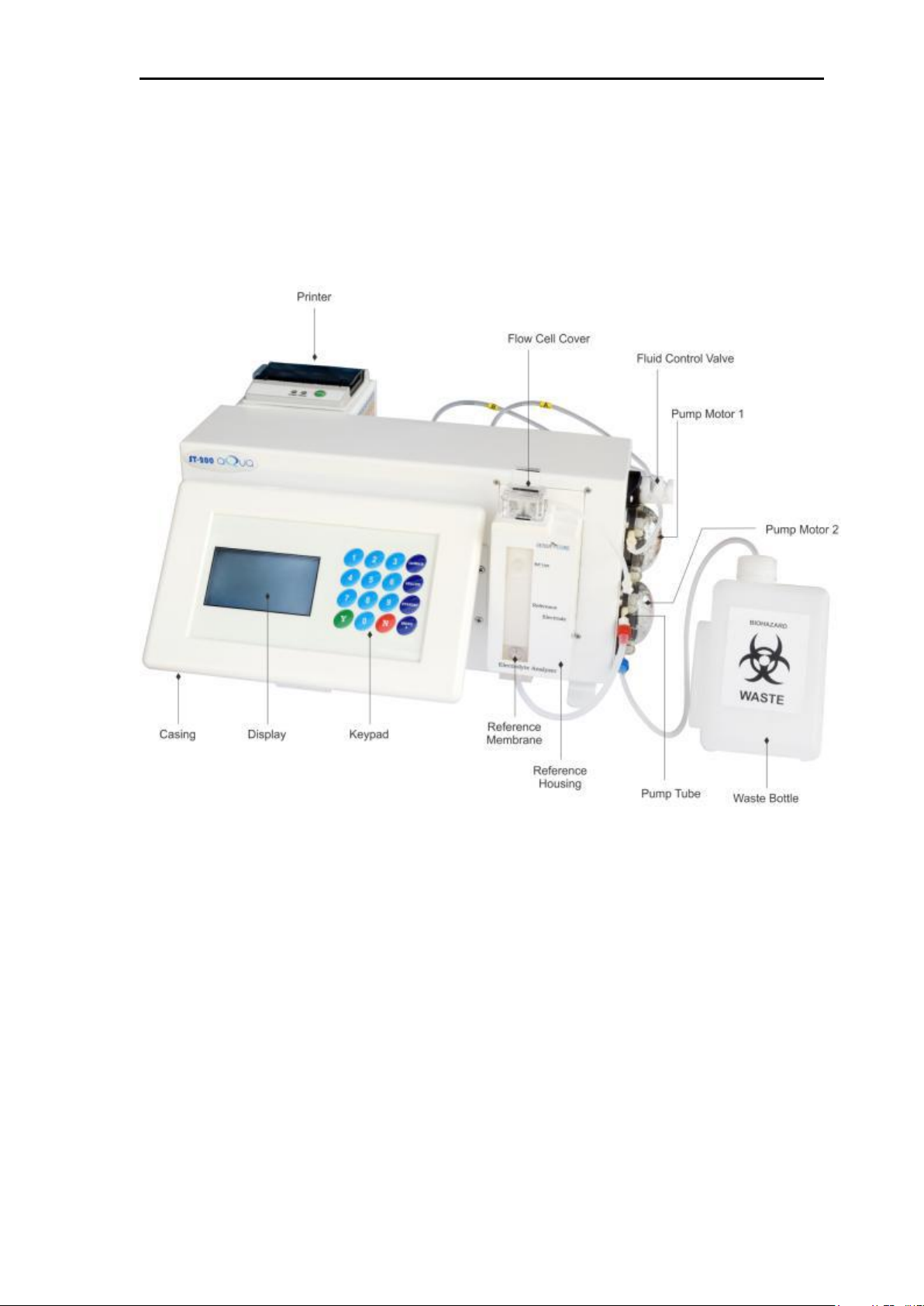
ST-200 aQua Operator’s Manual
C. Operational Hazards and Precautions
Read the operator’s manual before setting up or operating the ST-200
aQua electrolyte analyzer.
Observe all warnings, notes and key information in this manual.
Failure to leave the ST-200 aQua electrolyte analyzer to power with the
REAGENT PACK in place could damage the electrodes and cause blockage.
There are no operator serviceable parts inside the ST-200 aQua electrolyte
analyzer. If electromechanically problems are suspected, DO NOT attempt
to open the back cover. Contact your authorized technical service
representative.
The power cord of the ST-200 aQua electrolyte analyzer must be connected
to a matching ground outlet supplying 110 VAC, 50/60 Hz 0r 230 VAC,
50/60 Hz, as indicated on the label on the rear panel of the analyzer.
The ST-200 aQua electrolyte analyzer contains sensitive electronics and
must be properly grounded. The ST-200 aQua electrolyte analyzer should
not be plugged into a circuit protected by a GFI (Ground Fault Interrupter).
The environment should be as free as possible from dust, mechanical
vibrations, and electrical interference. Avoid proximity to brush-type
motors (certain type of centrifuges), diathermy instruments, flickering
fluorescent lights and arcing contacts of any kind. Do not install the ST-
200 aQua electrolyte analyzer near heat producing equipment or near
incandescent lighting.
BIOHAZARD
When collecting and handling biological specimens, the center for Disease
control (CDC) recommends that all samples be considered biohazards
which may be contaminated with HIV or other pathogens. Any replaceable
item which comes in contact with biological samples, including the sample
probe, solution valve, probe wipers, sample tube, sample detector,
electrodes, electrode connectors, membrane assembly, electrode housing,
pump tubing and solutions pack may contain potentially contaminated
material. Treat all components, during use and dispose, as you would use
any biohazardous material.